REFLECTANCE CALIBRATION SCHEME FOR AIRBORNE FRAME CAMERA
IMAGES
U. Beisl a
a Leica Geosystems AG, 9435 Heerbrugg, Switzerland – [email protected]
Commission VII, WG VII/1
KEY WORDS: Atmosphere, Modelling, Radiometric, Calibration, Processing, Multispectral, Digital, Camera
ABSTRACT:
The image quality of photogrammetric images is influenced by various effects from outside the camera. One effect is the scattered light from the atmosphere that lowers contrast in the images and creates a colour shift towards the blue. Another is the changing illumination during the day which results in changing image brightness within an image block. In addition, there is the so-called bidirectional reflectance of the ground (BRDF effects) that is giving rise to a view and sun angle dependent brightness gradient in the image itself. To correct for the first two effects an atmospheric correction with reflectance calibration is chosen. The effects have been corrected successfully for ADS linescan sensor data by using a parametrization of the atmospheric quantities. Following Kaufman et al. the actual atmospheric condition is estimated by the brightness of a dark pixel taken from the image. The BRDF effects are corrected using a semi-empirical modelling of the brightness gradient. Both methods are now extended to frame cameras. Linescan sensors have a viewing geometry that is only dependent from the cross track view zenith angle. The difference for frame cameras now is to include the extra dimension of the view azimuth into the modelling. Since both the atmospheric correction and the BRDF correction require a model inversion with the help of image data, a different image sampling strategy is necessary which includes the azimuth angle dependence. For the atmospheric correction a sixth variable is added to the existing five variables visibility, view zenith angle, sun zenith angle, ground altitude, and flight altitude - thus multiplying the number of modelling input combinations for the offline-inversion. The parametrization has to reflect the view azimuth angle dependence. The BRDF model already contains the view azimuth dependence and is combined with a new sampling strategy.
1. INTRODUCTION
Originally, photogrammetric camera systems were used for metric purposes in the geometric domain, i.e. for measuring distances, areas and angles. This was possible with the analog film cameras which provided sufficiently good contrast and sharpness. Attempts were made to use the wet film technology for radiometric measurements using densitometers, but the radiometric resolution was poor and the results were only stable within one film roll due to the influences of temperature and developer during film development.
With large format digital sensors becoming affordable for photogrammetric users ten years ago, new application areas have developed quickly. Remote sensing applications which could be handled only with calibrated satellite images can now be solved with airborne images, too. In addition, a new mass market for cheap high resolution images for use in internet based mapping systems has emerged. In addition to a minimal geometric accuracy the new applications require a balanced radiometry and removal of atmospheric artefacts.
When digital cameras appeared on the market the analog film data workflow had already turned digital by using film scanners. Therefore the geometric calibration algorithms could be easily transferred to the digital image data workflow. The radiometric processing of digital camera images had long been dominated by a mere relative calibration of the lens falloff.
However, the large field of view (FOV) and the varying flying height of airborne cameras introduce strongly varying effects of atmospheric stray light, giving rise to a blue hue, increasing
towards the borders of the images. Furthermore the effects of bidirectional ground reflectance (BRDF) cause varying brightness within the image, the most prominent ones being sunglint in the water and a hot-spot in the image at high sun elevation. To address these radiometric aspects an EUROSDR project was initiated (Honkavaara, 2011).
In order to correct those environmental artefacts in airborne images, methods from satellite and hyperspectral airborne image workflows were adapted to the needs of high-resolution photogrammetric images. Those methods use physical models which require an absolute calibration of the airborne sensors. The Leica ADS40 camera was the first commercial photogrammetric camera that provided an absolute radiometric calibration (Beisl, 2006). This was the prerequisite for applying an automated atmospheric correction in the photogrammetric workflow, which was implemented together with a BRDF correction (Beisl et al., 2008). The atmospheric correction option for ADS image data has become the standard setting in the image workflow for XPro users (Downey et al., 2010). A validation of the reflectance calibration has been presented by (Markelin et al., 2010) and (Beisl et al., 2010).
The Swiss Federal Office of Topography (swisstopo) is now using absolutely calibrated ADS images to produce two quality image products in an operational way (swissimage standard product and remote sensing basis product) (Schläpfer et al., 2012).
This paper gives an outline, how to extend the ADS radiometric correction algorithms for use in frame sensors like DMC (Ryan et al. 2009) or RCD30 (Wagner, 2011), (Tempelmann, 2012).
2. ATMOSPHERIC EFFECTS
2.1 Viewing Geometry
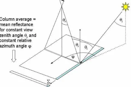
The viewing geometry of line sensors simplifies radiometric corrections considerably since for a single flight line the view azimuth φ is constant for every pixel, assuming the airplane movements are compensated by a stabilized platform. The area of a constant view zenith angle θr is an image column (cf. Figure 1).
Figure 1. Viewing geometry for a line scan sensor.
For frame sensors the area of constant view zenith angle is a circle and still has a varying view azimuth (cf. Figure 2).
Figure 2. Viewing geometry for a frame sensor.
2.2 Reflectance Calibration of Aerial Images
2.2.1 Radiative Transfer Equation: For the physical description of the nadir looking passive Earth observation the radiative transfer theory of Chandrasekhar is used (Fraser et al., 1992).
(
ρ
)
π
ρ
s
T
T
S
L
L
m down up−
+
=
1
0 (1)
where Lm = measured at-sensor radiance
L0 = path radiance for zero ground reflectance
ρ = surface reflectance
ρ = average surface reflectance of surrounding area S = mean solar spectral irradiance
Tdown = total downward transmittance from top of the atmosphere (TOA) to the ground
Tup = total upward transmittance from ground to sensor s = spherical albedo of the atmosphere, i.e. the fraction of the upward radiance which is backscattered by the atmosphere
For the case of atmospheric correction the surface reflectance ρ
has to be calculated from the observed at sensor radiance Lm. Solving eqn (1) for ρ gives:
(
)( )
ρ
π
ρ
s
T
T
S
L
L
up down
m
−
−
=
01
(2)
Suppose
ρ
is known then the quantities L0, Tdown, Tup, s, and S have to be calculated.The extraterrestrial irradiance S is given by a standard formula depending on the geographical latitude and the day of the year.
2.2.2 Model Inversion: Photogrammetric image processing has to deal with huge amounts of data, so a very efficient algorithm is needed to calculate L0, Tdown, Tup, and s. Therefore the modified Song-Lu-Wesely method described in (Beisl et al., 2008) is used.
The basic idea is the following: Standard atmospheric models calculate the at-sensor radiance, irradiance and transmittances based on a given ground reflectance, atmosphere and aerosol load. Since the ground reflectance is the unknown quantity, the model has to be inverted for a given at-sensor radiance. Unfortunately, none of the atmospheric parameters is known in case of aerial images. So standard values are assumed for all atmospheric and aerosol parameters except the horizontal visibility (which is related to the aerosol concentration) and, which has the biggest influence on the radiative transfer.
A series of forward model runs is performed with all combinations of the input variables (ground elevation, flying height, sun zenith angle, view zenith angle, relative azimuth angle, and visibility), giving a multi-dimensional look-up table. The total transmittances are calculated indirectly from runs at three ground reflectances, because radiative transfer programs will typically only output the direct transmittance between sun and ground and between ground and sensor.
The aim is to replace the non-observable quantity visibility by an observable quantity. The only available choice is the atmospheric reflectance δ0 in nadir view which is determined from the observed atmospheric reflectance δ of a dark pixel viewed from a certain view zenith and azimuth angle.
The atmospheric reflectance δ is defined here as the difference of the observed top-of-atmosphere (TOA) reflectance α and the ground reflectance ρ of the dark pixel (eqn 3). The TOA reflectance is calculated from the at-sensor radiance Lm and the TOA irradiance S (eqn 4).
ρ
α
δ
≡
−
(3)S
L
mπ
α
≡
(4)For the dark pixel we assume an average reflectance ρ of 2 %. If the true reflectance spectrum of the dark pixel were known, a more accurate modelling would be possible. But if a wrong spectrum is taken then the whole image will be calibrated with this spectral error. Therefore a spectrally constant dark pixel reflectance is chosen.
2.2.3 Modelling of Atmospheric Quantities: Now δ0 can be
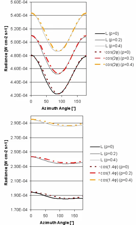
Since δ0 is a nadir looking quantity there is no explicit azimuth angle dependence. However, the parametrization has to compensate the azimuth angle dependence of the observed atmospheric reflectance δ at view zenith angle θr. The azimuth angle dependence of δ is caused by the path radiance L0 which is defined as the total radiance at ground reflectance 0. The total radiance is shown for several ground reflectances in Figure 3 for a visibility of 3 km. For a satellite view the variation of L0 can be modelled with a cos(2*φ) dependence since it is caused mostly by Rayleigh scattering. For an airborne view at 1 km elevation of 100 km (upper image) and 1 km (lower image). A different ground reflectance ρ only adds a constant radiance offset. The variation can be modelled with a cosine function.
The atmospheric reflectance δ0 is the scaling factor for the other atmospheric quantities L0, Tdown, Tup, and s. They are calculated as a function of the observed atmospheric reflectance δ0, the view zenith angle θr, the sun zenith angle θi, the ground level H, the flight altitude over ground h and a set of fixed parameters (b1...b7, c1...c6, d1...d3, e1...e6). The parameters for the quantities in eqns (5)-(9) can be obtained using a multilinear regression from a sufficient number of model runs with all combinations of the input variables.
2.2.4 Broadband Sensors: The above calculation is strictly valid only for a single wavelength and the outputs being spectral densities. The evaluation of eqn (2) gives the contribution to the reflectance at this wavelength. For a broadband sensor the contributions of a spectral density x have to be integrated over the spectral response curve of the sensor using eqn (10) to give the band-averaged quantity.
( ) ( )
This would require to parametrize the quantities in eqns (5)-(9) for each wavelength separately which is not practical. So the parametrization is done for the band averaged quantities in eqns (5)-(9) and the reflectance is then calculated from the band-averaged quantities. (Richter, 2000) has found that the errors in the VISNIR range (400-1000 nm) are below 2% and therefore below the calibration accuracy.
In the special case of a narrowband sensor with spectral sensitivities away from the gaseous absorption bands (like e.g. the ADS) the atmospheric quantities L0, Tdown, Tup, and s change moderately with wavelength. Then the radiative transfer calculations can be made by using the effective bandwidth of the sensor and simply averaging the spectral quantities over the effective bandwidth without using the spectral response function as a weight.
2.2.5 Reflectance Calibration for Images: Eqns (2) and (5)-(9) allow a fast image calibration to ground reflectance without any iteration. Since multiple scattering is a second order process
ρ
can be assumed constant and an average value of 0.15 for a midlatitude landscape is used.2.3 Bidirectional Reflectance
2.3.1 Sampling and Model Inversion: As mentioned in (Beisl et al., 2004) the bidirectional reflectance process is influenced mainly by microscopic shadow casting and volume scattering processes with unknown influencing parameters. So the correction process also requires a model inversion.
As suggested by the viewing geometry shown in sec. 2.1 the sampling has to be done in image columns for the line scan
sensor and in concentric circles of constant view azimuth angle for frame sensors. In addition, those circles have to be split up in segments for different relative azimuth angle.
Due to missing sampling redundancy physical models cannot be used and are impractical for the large variety of surface types in a typical aerial image. So it is favourable to use linear semi-empirical kernel models like those developed by (Wanner et al., 1995). The inversion of linear models is a least squares regression and results in a simple matrix inversion while models with non-linear parameters would require calculation-intensive adaptive inversion algorithms. For the correction step which requires many forward calculations, simple kernel functions are preferable.
As suggested in (Beisl et al., 2004) even a simple 3-parameter Walthall model (Walthall et al., 1985) without distinguishing between different ground types (“global correction”) shows good results (eqn 11). There is an extended version including a varying sun zenith angle (Nilson and Kuusk, 1989) (eqn 12).
c
θi = incident illumination zenith angle
θr = reflection view zenith angle
φ = relative azimuth angle
a, b, c, d = free parameters
Since the Walthall model does not include a hot spot term a simple empirical elliptical kernel function (eqn 13) is added to eqn (11) and (12) which is inspired by the hot spot distance function of the Li-kernels from the AMBRALS model (Wanner et al., 1995). BRDF correction and eqn (11) can be used.
However, to cover larger areas, images are acquired in blocks with large overlap (60 % - 80 %) for stereo measurements. In order to make use of the redundancy and to ensure the proper radiometric matching of consecutive images a sliding window technique can be used by sampling the current image together with the previous and the following image and invert this set of samples to give the modelling function for the middle image.
Depending on the block size, neighbouring flight lines may have considerable time offsets due to the flight planning schedule and therefore require considering the sun zenith angle as modelling variable. algorithm that prevents water areas from being sampled. This is
because the water BRDF is of a specular reflectance type which is contrary to the land BRDF which is of a hot-spot type.
2.3.2 BRDF correction: Since the reflection process is a linear function of irradiance, a multiplicative correction by the ratio of the model values at the final geometry to the model values at the original geometry is used.
(
θ
ϕ
) (
ρ
θ
ϕ
) ( ) (
(
θ
θ
ϕ
)
)
correct for radiometric distortions in photogrammetric images caused by environmental effects. The idea is to include as much physical information as is available into those corrections in order to give a true copy of the reality as if it were seen from the ground. This information includes absolute radiometric sensor calibration, solar position, and haze information.As a future step, measured ground spectra can be used to perform an in-flight calibration to improve the absolute radiometric calibration for remote sensing purposes (i.e adjust the calibration factors such that the measured spectra match with the spectra of the corresponding atmospherically corrected and reflectance calibrated pixels).
Furthermore a class specific BRDF correction should be implemented to better adapt to the specific surface properties. Therefore a proper classification has to be made with a special treatment of the class boundaries.
The atmospheric correction could be improved with the correction of the local adjacency effect to enhance the contrast in the image and also include to correction of topographic effects by varying terrain height, surface tilt and change in diffuse illumination by the percentage of visible sky. Also a shadow correction would be a favourable, but challenging add-on.
However, the guideline for the implementation of any new feature must be the operational and efficient processing, and that no new artefacts are introduced.
4. REFERENCES
Beisl, U., and Woodhouse, N., 2004. Correction of atmospheric and bidirectional effects in multispectral ADS40 images for mapping purposes. In: Int. Arch. Photogramm. Remote Sens., Istanbul, Turkey, Vol. XXXV, Part B7, 5 pp.
Beisl, U., 2006. Absolute spectroradiometric calibration of the ADS40 Sensor. In: Int. Arch. Photogramm. Remote Sens., Paris, France, Vol. XXXVI, part 1, 5 pp.
Beisl, U., Telaar, J., and Schönermark, M.v., 2008. Atmospheric correction, reflectance calibration and BRDF correction for ADS40 image data. In: Int. Arch. Photogramm.
Remote Sens., Beijing, China, Vol. XXXVII, part B7, pp. 7-12.
Beisl, U., and Adiguezel, M., 2010. Validation of the reflectance calibration of the ADS40 airborne sensor using
ground reflectance measurements. In: Int. Arch. Photogramm.
Remote Sens.,Vienna, Austria, Vol XXXVIII, Part7B, pp.
80-85.
Chandelier, L., and Martinoty, G., 2009. A Radiometric Aerial Triangulation for the Equalization of Digital Aerial Images and Orthoimages. Photogrammetric Engineering and Remote
Sensing, 75(2), pp. 193-200.
Downey, M., Uebbing, R., Gehrke, S., and Beisl, U., 2010. Radiometric processing of ADS imagery: Using atmospheric and BRDF corrections in production. In: Proc. ASPRS 2010, San Diego, USA, 9 pp.
Fraser, R. S., Ferrare, R. A., Kaufman, Y. J., Markham, B. L., and Mattoo, S., 1992. Algorithm for atmospheric corrections of aircraft and satellite imagery. Int. J. Rem. Sens., 13(3), pp. 541-557.
Hernández López , D., Felipe García, B., González Piqueras, J., and Villa Alcázar, G., 2011. An approach to the radiometric aerotriangulation of photogrammetric images. ISPRS Journal of
Photogrammetry and Remote Sensing, 66(6), pp. 883–893.
Honkavaara, E., Arbiol, R., Markelin, L., Martinez, L., Bovet, S., Bredif, M., Chandelier, L., Heikkinen, V., Korpela, I., Lelegard, L., Pérez, F., Schläpfer, D., and Tokola, T., 2011. The EuroSDR project "Radiometric Aspects of Digital Photogrammetric Images" - Results of the empirical phase. In:
Int. Arch. Photogramm. Remote Sens., Hannover, Germany,
Vol XXXVIII-4/W19, 8p.
Markelin, L. Honkavaara, E., Beisl, U., and Korpela, I., 2010. Validation of the radiometric processing chain of the Leica ADS40 airborne photogrammetric sensor. In: Int. Arch.
Photogramm. Remote Sens., Vienna, Austria, Vol XXXVIII,
part7A, pp. 145-150.
Nilson, T., and Kuusk, A., 1989. A reflectance model for the homogeneous plant canopy and its inversion. Remote Sens.
Environ., 27, pp. 157-167.
Richter, R., 2000. Bandpass-resampling effects on the retrieval of radiance and surface reflectance. Applied Optics, 39(27) pp. 5001-5005.
Ryan, R. E., and Pagnutti, M., 2009. Enhanced absolute and relative radiometric calibration for digital aerial cameras. Proc.
Photogrammetric Week 2009, Stuttgart, Germany, pp. 81-90.
Schläpfer, D., Richter, R., and Kellenberger, T., 2012. Atmospheric and topographic correction of photogrammetric airborne digital scanner data (ATCOR-ADS). In: Proc.
European Calibration and Orientation Workshop, EuroCOW 2012, Castelldefels, Spain, 5 pp.
Tempelmann, U., Beisl, U., Boehrer, N., Hinsken, L., and Recke, U., 2012. Creating virtually distortion-free multi-band frame images: laboratory and flight calibration techniques for the Leica RCD30. In: Proc. European Calibration and
Orientation Workshop, EuroCOW 2012, Castelldefels, Spain, 8
pp.
Walthall, C. L., Norman, J. M., Welles, J. M., Campbell, G., and Blad, B. L., 1985. Simple equation to approximate the bidirectional reflectance from vegetative canopies and bare soil surfaces. Appl. Opt., 24(3), pp. 383-387.
Wagner, R., 2011. The Leica RCD30 Medium Format Camera: Imaging Revolution. In: Fritsch D. (Ed.), Photogrammetric
Week 2011, Stuttgart, Wichmann, pp. 89-95.
Wanner, W., Li, X., and Strahler, A. H., 1995. On the derivation of kernels for kernel-driven models of bidirectional reflectance. J. Geophys. Res., 100(D10), pp. 21077-21089.