AN AUTOMATIC PROCEDURE FOR COMBINING DIGITAL IMAGES AND LASER
SCANNER DATA
Wassim Moussa, Mohammed Abdel-Wahab, Dieter Fritsch
Institute for Photogrammetry (ifp), University of Stuttgart, Geschwister-Scholl-Str. 24D, 70174 Stuttgart, Germany
Commission V, WG V/3
KEY WORDS: Fusion, Close Range, Photogrammetry, Laser scanning, Matching, Registration, Orientation
ABSTRACT:
Besides improving both the geometry and the visual quality of the model, the integration of close-range photogrammetry and terrestrial laser scanning techniques directs at filling gaps in laser scanner point clouds to avoid modeling errors, reconstructing more details in higher resolution and recovering simple structures with less geometric details. Thus, within this paper a flexible approach for the automatic combination of digital images and laser scanner data is presented. Our approach comprises two methods for data fusion. The first method starts by a marker-free registration of digital images based on a point-based environment model (PEM) of a scene which stores the 3D laser scanner point clouds associated with intensity and RGB values. The PEM allows the extraction of accurate control information for the direct computation of absolute camera orientations with redundant information by means of accurate space resection methods. In order to use the computed relations between the digital images and the laser scanner data, an extended Helmert (seven-parameter) transformation is introduced and its parameters are estimated. Precedent to that, in the second method, the local relative orientation parameters of the camera images are calculated by means of an optimized Structure and Motion (SaM) reconstruction method. Then, using the determined transformation parameters results in having absolute oriented images in relation to the laser scanner data. With the resulting absolute orientations we have employed robust dense image reconstruction algorithms to create oriented dense image point clouds, which are automatically combined with the laser scanner data to form a complete detailed representation of a scene. Examples of different data sets are shown and experimental results demonstrate the effectiveness of the presented procedures.
1. INTRODUCTION
Close range photogrammetry and terrestrial laser scanning (TLS) are two typical techniques to reconstruct 3D objects. Both techniques enable the collection of precise and dense 3D point clouds. Unfortunately, there is still no optimal approach or procedure which is adequate for all applications and their demands. These demands principally relate to the geometric accuracy, photorealism, completeness, automation, portability, time and cost. TLS directly hands over 3D object points through an array of coordinates. These point clouds have no information about the object texture which leads to the need of photogrammetry. Photos contain the required texture but do not contain any explicit metric information without further processing steps such as the introduction of a scale bar or the introduction of ground control points.
In addition, in case of spatially complex objects and difficult topography such as heritage sites, a complete coverage of data collection from different viewpoints is required. This can face obstacles requiring setting up and dismounting the laser scanner. Furthermore, the acquisition distance is limited. Accordingly, TLS data acquisition can be relatively time and effort consuming. Unlike, a negligible effort and time are needed to capture additional images with a standard digital camera.
To achieve an improved quality of procedures and results than could be achieved by the use of a single sensor alone, a fusion of photogrammetric images and laser scanner data must be performed. Consequently, and due to the complementary
characteristics of both digital images and laser scanner data, this combination will promote issues that need to be investigated such as filling gaps in laser scanner data to avoid modeling errors, reconstructing more details in higher resolution and recovering simple structures with less geometric details.
Thus, we propose a processing chain for combining photogrammetric images and laser scanner point clouds based on a scene database stored in a point-based environment model (PEM). The PEM allows the extraction of accurate control information for direct absolute camera orientation. Based on well-known strategies and algorithms, several tasks (data pre-processing, image matching, registration and dense image matching) have been solved efficiently in order to ensure accuracy and reliability. So the related work is briefly introduced in the following section. Section 3 describes the data acquisition and pre-processing in detail. A description of the PEM is presented in section 4. Section 5 describes the marker-free registration of images. Section 6 demonstrates the experimental results.
2. RELATED WORK
Over the past few years, different fusion approaches were presented to integrate digital photos with laser scanner data. These approaches were useful in texture mapping of point clouds to generate 3D photorealistic models, extraction of reference targets for registration and calibration tasks, registration of multiple scans by using photos, employing photos to reconstruct the main shape of the object and then using laser scanning to reconstruct the detailed parts (El-Hakim International Archives of the Photogrammetry, Remote Sensing and Spatial Information Sciences, Volume XXXIX-B5, 2012
et. al., 2003), and last but not least filling gaps in laser scanner point clouds caused by occlusions (Alshawabkeh, 2006). Constructive on that we propose a fully automatic method for the integration of digital imagery and laser scanning point clouds.
The prerequisite for the combination of digital images and laser scanner data is finding a registration approach that comprises advantageous characteristics in terms of precision, reliability and simplicity. In general, the registration process can either proceed automatically or manually by placing artificial targets into the scene. The latter can be time and effort consuming, so it is worthwhile to use the former one. Typical automatic registration approaches use distinctive features for the registration of digital images and point clouds. These features have to be matched in both sensors.
Basically two images can be generated from TLS data, the reflectance and the RGB images. The former is generated from the intensity values while the latter is generated from the RGB values. Employing the generated images will simplify the extraction of distinctive features from 3D point clouds to a 2D problem. Accordingly, registering both sensors will be based on a matching between both the generated and the camera images, see (Alba et al., 2011).
Consequently, each sample in the PEM is not only associated with a reflectance value, but also with a RGB value. Therefore we employed the generated images in order to build a PEM database which includes a list of distinctive features with their descriptors extracted from both generated images. As a result, our proposed fusion procedure is firstly based on the potential to develop an efficient pipeline able to fuse data sources and sensors for different applications. Secondly it yields at an increase in automation and redundancy. Finally, it represents a direct solution for data registration.
3. DATA ACQUISITION AND PRE-PROCESSING
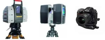
A Leica ScanStation HDS 3000 and a Faro Laser Scanner Focus3D, figure 1 (left and center) respectively, were used to perform the laser scanner measurements. The former is a time-of-flight-based laser scanner operating at a wavelength of 532 nm, for more details see (Böhm, 2007). The latter is a phase shift-based laser scanner operating at a wavelength of 905 nm. It sends the infrared laser beam into the center of a rotating mirror. The mirror deflects the laser on a vertical rotation around the scene being scanned; scattered light from surroundings is then reflected back into the scanner. The range measurements are accurately determined by measuring the phase shifts in the waves of the infrared light. The Cartesian coordinates of each point are then calculated by using angle encoders to measure the mirror rotation and the horizontal rotation of the scanner. The scanner has a maximum field of view of 360o × 305o in horizontal and in vertical respectively, with a high measurement speed: up to 976 kpts/sec can be obtained. The possible standoff range is 0.6 to 120 meters. The manufacturer specifies the maximum ranging error with ±2mm at 10 to 25 meters. Experiments for this study were demonstrated using different datasets. The old farm building and the Lady Chapel of the Hirsau Abbey ruins, see (Moussa & Fritsch, 2010), datasets were acquired by the Leica HDS 3000 at an approximate sampling distance of 2cm and 5cm
respectively on the object’s surface. Furthermore, the Stuttgart
University building dataset was acquired using the Faro Focus3D
Figure 1. The employed sensors. From the left, Leica Scan Station HDS 3000, Faro Laser Scanner Focus3D and NIKON D2X digital camera
at an approximate sampling distance of 2cm on the object’s surface.
Digital photographs have been captured by a standard calibrated digital camera NIKON D2X (12 Mpx) with 20mm lens (figure 1-right). The collected imagery require the following process: correction of image distortions; considering only the green channel in order to get similar intensity values in the generated and the camera images and to reduce illumination differences; resizing digital images to fit as good as possible to the ground sampling of the generated images in order to ensure optimal matching performance.
4. POINT-BASED ENVIROMENT MODEL
The point-based environment model is introduced in (Böhm, 2007) as a dense point-wise sampling of the scene surface that can easily be acquired by long-range 3D sensors, such as TLS systems and machine vision cameras. Where each sample is located in an approximately regular polar grid and comprised of the 3D coordinates of the point associated with an intensity value. The PEM features are extracted from the corresponding reflectance image by direct mapping of the laser scanner polar coordinates. This requires, according to the scanning mechanism of the laser scanner, one scan section that comprises one image matrix. Consequently, this method is limited and inflexible especially in case of having multiple sections in one scan.
Moreover, in this representation, straight object lines are mapped as curved lines in the generated images. Contrarily, camera images are provided with central perspective lenses. This causes changes in the grey values along the object lines not only due to the different illuminations but also to the different geometries. Additionally, the resulting reflectance image requires visual enhancement (histogram equalization) because of the poor contrast. Accordingly, imaging laser scanner polar coordinates as a 2D representation may intricate the feature matching process between the reflectance and the camera images.
Therefore, we expand the point-based environment model as follows. Since terrestrial laser scanners provide for each measurement intensity and RGB values, we stored these values in the PEM. This extension has an important advantage, because instead of using only intensity values, a similar approach can be also applied on RGB. This results in extracting redundant information from both generated images. Moreover, the intensity values are recorded as the energy of the reflected laser beam, which locally illuminates the surface at a very narrow bandwidth of the laser beam. This may outcome in missing some good features which are not visible at the narrow bandwidth of the light source (Böhm, 2007).
Figure 2. Dataset of Stuttgart University building, (from the left) 3D laser point cloud, RGB image of Faro Focus3D and our
generated RGB image
To avoid difficulties in the feature matching process and the disagreements between both the generated and the camera images, it would be worthwhile to project the laser point cloud into a central perspective representation (Meierhold et. al., 2010).
Furthermore, despite of the high advance in LiDAR systems, e.g. the Faro Focus3D, they still deliver reflectance and RGB images with mapped curved lines based on the scanning mechanism (see figure 2-center). Therefore, we propose a flexible method to generate the reflectance and the RGB images based on the collinearity equation (1) in order to project each point cloud into a virtual image plane, as shown in figure 2 right.
11 0 21 0 31 0
13 0 23 0 33 0
12 0 22 0 32 0
13 0 23 0 33 0
r ( ) r ( ) r ( )
r ( ) r ( ) r ( )
r ( ) r ( ) r ( )
r ( ) r ( ) r ( )
X X Y Y Z Z
x c
X X Y Y Z Z
X X Y Y Z Z
y c
X X Y Y Z Z
(1)
where (x,y) are the unknown image coordinates, ( X , Y , Z ) constitute the corresponding known object coordinates in the laser point cloud, (X0,Y0,Z0,r ) denote the known exterior i j
orientation parameters since we assume that the camera is placed in the same position as the laser scanner. The parameter (c) represents the defined focal length to accomplish the projection into the generated image which is set to the same value of the camera image in order to achieve good results.
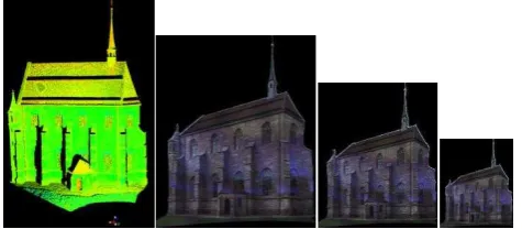
Figure 3. Lady Chapel dataset. From the left, 3D laser point cloud and generated RGB images with different pixel footprints;
interval distance in object space (3, 8 and 13 cm)
Up to now, all 3D point clouds have been projected into the image plane. Practically, to generate the reflectance and RGB images, it is sufficient to have one projected point per pixel. However, using an interpolation process, more projected points per pixel will improve the accuracy of the 3D coordinates of the extracted features in the generated images. On the other hand, the interpolation process will also fill any image pixel, which does not contain information. As a result, the pixel size is calculated from projecting the required interval distance onto
Figure 4. Old farm dataset, 3D laser point cloud (left) and the matched features on the RGB image (right). In close, the nearest
neighbors (green) used to interpolate the corresponding object coordinates for each feature (yellow)
the image plane. Accordingly, the pixel size has a direct effect on the required image resolution and the desired number of projected points in image pixel (figure 3).
As the extracted features from the generated images are located with subpixel accuracy, the corresponding 3D locations have to be calculated using an interpolation process based on weighted distances of nearest neighbors measurements (see figure 4). In case that the range measurements are not available for all neighboring points (e.g. 4 neighbors) in the PEM, this point will be excluded. For that we employed the Fast Library for Approximate Nearest Neighbors (Muja & Lowe, 2009) and the kd-tree implementation in the VLFeat library 0.9.14 (Vedaldi & Fulkerson, 2010). The generated PEM plays a key role to provide accurate control information for direct absolute orientation of Hand-held cameras.
4.1 Feature Extraction
The generated images from laser point clouds and camera images indicate differences related to image resolution, radiometry, direction of illumination and viewing direction. As a consequence, the identification of corresponding points between generated and camera images requires a robust feature matching algorithm, which is insensitive to illumination and scale differences and employs region descriptors instead of edge detectors (Böhm & Becker, 2007). A wide variety of feature operators have been proposed and investigated in the literature, see e.g. (Tuytelaars & Mikolajczyk, 2007). Generally, repeatability is the most important attribute for a feature operator, which indicates the capability of finding the same exact feature under different viewing and illumination conditions (Barazzetti et al., 2010). (Valgren & Lilienthal, 2007) addressed the high repeatability of SIFT (Lowe, 2004) and SURF (BAY et al., 2008) operators in the case of terrestrial images.
(Morel & Yu, 2009) propose the affine SIFT (ASIFT) feature detection algorithm which extends the SIFT method to fully affine invariant local image features. The ASIFT method simulates a set of sample views of the initial images, obtainable by varying the two camera axis orientation parameters, namely the latitude and the longitude angles, which are not treated by the SIFT method. Then it applies the SIFT method itself to all images thus generated. Therefore, ASIFT covers effectively all six parameters of the affine transform. (Morel & Yu, 2009) illustrate that most scenes with negligible or moderate camera view angle change that match with ASIFT also match with SIFT (usually fewer matching points). Nevertheless, when the view angle change becomes important, SIFT and other methods fail while ASIFT continues to work. Thus, ASIFT has been chosen for our experiments.
5. IMAGE REGISTRATION
Finding the mathematical mapping by calculating the relative orientation between the digital images and the extended PEM database is referred as sensor registration. Most registration approaches are classified according to their nature (area-based and feature-based) and according to four basic steps of image registration procedure: feature detection, feature matching, transform model estimation and image transformation and resampling (Zitoza & Flusser, 2003). So, in the next paragraphs, a marker-free registration pipeline of camera images based on a feature matching process with the PEM database’s features is introduced. This process involves determination of correspondences and calculation of camera orientation.
5.1 Determination of Correspondences
Feature Extraction: As mentioned in section 4.1, ASIFT operator has been used for feature detection and description in camera images.
Feature Matching and Filtering: ASIFT associates a descriptor to each detected image feature following the standard SIFT operator. Interest feature matching is performed by employing a pair-wise comparison of descriptor space distances for interest features in each camera image and the PEM database, without any preliminary information about the image network or epipolar geometry. Since the PEM features are linked to their 3D coordinates, a standard RANSAC filtering scheme (Fischler & Bolles, 1981) is adapted to a closed-form space resection algorithm proposed by (Zeng & Wang, 1992) as a mathematical model in order to exclude mismatches.
5.2 Camera Orientation Based on Accurate Space Resection
Once the 3D-to-2D correspondences are known, the exterior camera orientation relative to the laser scanner data (PEM) is resulting from solving the Perspective-n-Point (PnP) problem, also known as space resection in photogrammetry. The latter aims at estimating the camera orientation from a set of 3D-to-2D point correspondences. So, accurate space resection methods are employed in order to compute the absolute orientation of the camera using redundant information. To improve efficiency and accuracy, an outlier rejection procedure based on the noise statistics of correct and incorrect correspondences is applied.
Accurate Camera Space Resection: Accurate space resection methods determine the orientation of a camera given its intrinsic parameters and a set of correspondences between 3D points and their 2D projections. These methods have received much attention in both Photogrammetry and Computer Vision. Particularly, in applications which are computationally expensive such as feature point-based camera tracking (Lepetit & Fua, 2006) which handle hundreds of noisy feature points in real-time. However, for redundant data handling, the most accurate methods for solving space resection problem rely on iterative optimization methods (Lu et al., 2000). An essential prerequisite for iterative methods is having a reasonable initial estimate. With poor initial values it will be prone to failure. In this application, we use the Efficient Perspective-n-Point (EPnP) algorithm (Moreno-Noguer et al., 2007). EPnP proposed as a non-iterative solution to the PnP problem, which
is able to consider nonlinear constraints but requires only O(n) operation. It is used to calculate a good initial guess for the orthogonal iteration (OI) algorithm (Lu et al., 2000), which minimizes the error metric based on collinearity in object space, in order to estimate efficiently the camera pose.
It is worthwhile to mention that, in case of using an amateur digital camera for photograph’s collection, we can consider the results of EPnP method as initial values in the extended collinearity equations by adding additional camera parameters in order to estimate the camera calibration.
Outlier Rejection Procedure: To improve the estimated camera pose in terms of accuracy, a statistical outlier removal process is applied to the image reprojection errors in order to discard the remaining false correspondences and discriminate the good ones. This has been considered under the assumption that a normal (Gaussian) distribution of the residual for the good correspondences is present. We employed a simple but effective rejection rule, called X84 (Hampel et al., 1986) which utilizes robust estimates for location and scale, i.e., the spread of the distribution, to set a rejection threshold.
5.3 Structure and Motion Reconstruction
Reconstruction of camera orientations and structure from images is one of the most important tasks in Photogrammetry. The Structure and Motion (SaM) reconstruction method was originally developed by the Computer Vision community to simultaneously estimate the scene structure and the camera motion from multiple images of a scene.
For the derivation of accurate exterior orientations, we implemented an efficient SaM reconstruction method. It derives the exterior orientations without initial values by sequentially adding images to a bundle. Therefore, features are extracted from the imagery and matched to each other. By using an initial network analysis step large sets of images can be processed efficiently without performing this step for each available image pair. The number of unknowns within the SaM process can be reduced by using the interior orientation determined in the test field calibration. Therefore, the images are rectified by removing the distortion. For more details and accuracy analyses of our implementation see (Abdel-Wahab et al., 2011).
6. RESULTS AND DISCUSSIONS
6.1 Data set
In order to evaluate our results, the developed pipeline was applied to the dataset of the old farm building which is considered as a typical application for TLS. The aim was to reconstruct the missing upper right part of the façade which was not measured in this scan during the data acquisition due to standoff distance and angle limitations. 19 photographs have been employed for SaM reconstruction and marker-free registration.
6.2 Evaluation of Correspondences
Using the ASIFT operator, in the generated images (1193x597 pixels) and resized camera images (1201x797 pixels), the image features were extracted. This is followed by a feature matching process based on a quadratic matching procedure. Then, a filtering step using RANSAC based on a closed form space resection was accomplished (see Figure 5).
Figure 5. Feature point correspondences for 19 images of the farm building dataset, correspondences after ASIFT matching
(red), the results after RANSAC filtering (blue) and after statistical outlier removal X84 (green)
6.3 Camera Orientation
EPnP was employed to estimate the camera orientation. The X84 rule was applied during the estimation in order to remove outliers (see figure 5). Accordingly, the overall precision of the camera orientation is in sub-pixel range, which can be improved by the iterative method (OI). In order to assess the accuracy of the camera orientation, we have performed manual measurements to compute the camera orientation using the
“Australis” software package. These results were also compared to the camera orientation resulting from the SaM method, which have been transformed by the calculated Helmert parameters. Figure 6 shows that the camera orientations computed with the automatic methods (OI & SaM) give the same results as the manual method (Australis).
Figure 6. Comparison of the SaM and OI method’s results. Residuals of camera orientations, using Australis results as a reference, for three images with different viewing directions. X,
Y, Z are the camera position and qi is the quaternion rotation value.
6.4 Dense image matching
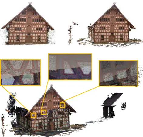
Using the absolute camera orientations, we have reconstructed a georeferenced, accurate and dense point cloud from the corresponding camera images. For that, we applied dense image matching algorithms - in particular, patch-based multi-view stereo (PMVS) method (Furukawa & Ponse, 2010) and a hierarchical multi-view stereo based on the Semi-Global Matching (SGM) method (Hirschmüller, 2008). The latter was developed in our institute (ifp), see (Wenzel et al., 2011). These methods have been employed in order to reconstruct oriented dense image point clouds which are automatically combined together with the laser scanner data to form a complete detailed representation of the scene (Figure 7). We can see that the dense image point cloud fits correctly to the laser point cloud. The generated dense image point cloud using SaM results contains almost no noise. On the contrary, one can see few noises in the generated dense point cloud by using the image registration
outputs. However, the results are still sufficient for our application and others which require small image datasets like filling of gaps in laser point cloud. Further complementary improvement using ICP as a fine registration technique is possible.
7. CONCLUSIONS AND FUTURE WORK
Within the paper, a procedure for automatic combination and co-registration of digital images and terrestrial laser data was presented. The method uses images generated from a PEM acquired by TLS and stores the laser point cloud’s 3D coordinates associated with intensity and RGB values. A marker-free registration of images based on matching the PEM and camera features was presented. Direct absolute camera orientations were computed by means of accurate space resection methods. These results were used to calculate the Helmert (seven-parameter) transformation in order to transform the local relative orientation parameters of the camera images calculated by an optimized SaM method. With the resulting absolute orientations dense image reconstruction algorithms were used to create oriented dense image point clouds automatically aligned with the laser scanner data, with a chance to reduce the final co-registration error with the help of global point cloud algorithms like ICP.
Possible improvements could be considered such as using linear features instead of point features for matching in order to reduce outliers and to improve registration accuracy. Furthermore, employing planar patches could lead to better accuracies in the final co-registration. Future work will explore this pipeline to support applications such as the filling of gaps in laser point clouds, the colorization of laser point clouds and the generation of orthophotos.
Figure 7. Dense image point cloud generated by PMVS combined together with the old farm‘s laser point cloud (bottom), dense image point cloud generated by the SGM using SaM outputs, about 5 million pts (upper left) and dense image point cloud generated by the PMVS using OI outputs, about 0.5 million pts (upper right)
SaM results OI results
X Y Z q1 q2 q3 q4
8. REFERENCES
Abdel-Wahab, M., Wenzel, K. & Fritsch D., 2011. Reconstruction of Orientation and Geometry from large Unordered Datasets for Low Cost Applications. Proceedings LC3D Workshop, Berlin.
Alba, M., Barazzetti, L., Scaioni, M., Remondino, F., 2011. Automatic registration of multiple laser scans using panoramic RGB and intensity data. Int. Archives of Photogrammetry, Remote Sensing and Spatial Information Sciences, Vol. 38(5/W12). Int. Conference "Laser Scanning 2011", Calgary, Canada.
Alshawabkeh, Y., 2006. Integration of Laser Scanning and Photogrammetry for Heritage Documentation. Dissertation, Universität Stuttgart.
Barazzetti, L., Scaioni, M., Remondino, F., 2010. Orientation and 3D modelling from markerless terrestrial images: combining accuracy with automation. The Photogrammetric Record 25(132): 356–381.
Bay, H., Ess, A., Tuytelaars, T., Van Gool, L., 2008. Speeded Up Robust Features (SURF). Computer Vision and Image Understanding (CVIU), Vol. 110, No. 3, pp. 346-359.
Böhm, J., Becker, S., 2007. Automatic marker-free registration of terrestrial laser scans using reflectance features. In: Gruen, A., Kahmen, H. (Eds.), Optical 3-D Measurement Techniques VIII, pp.338-344.
Böhm J., 2007. Orientation of image sequences in a point-based environment model. IEEE 3DIM, pp. 233-240, Sixth international conference on 3-D digital image and modeling.
El-Hakim, S., Beraldin, J.-A., Picard, M., and Vettore, A., 2003c. Effective 3D modeling of heritage sites, 4th Int. Conf.
3D Imaging and Modeling (3DIM’03),Banff, Canda, pp.30 2-309.
Fischler, M. A. & Bolles, R. C., 1981. Random Sample Consensus: A Paradigm for Model Fitting with Applications to Image Analysis and Automated Cartography. Communications of the ACM, Vol. 24(6), pp. 381-395.
Furukawa, Y.; Ponce, J., 2007. Accurate, dense, and robust multi-view stereopsis. IEEE Conference on Computer Vision and Pattern Recognition. 17-22 June 2007 , pp. 1-8.
Hampel, F., Rousseeuw, P., Ronchetti, E., and Stahel, W., 1986. Robust Statistics: The Approach Based on Influence Functions, Wiley Series in Probability and Mathematical Statistics, Wiley, New York, pp. 56–70, 104–106.
Hirschmüller, H., 2008. Stereo Processing by Semi-Global Matching and Mutual Information, IEEE Transactions on Pattern Analysis and Machine Intelligence, Volume 30(2), pp. 328-341.
Lepetit, V. and Fua, P., 2006. Keypoint recognition using randomized trees. IEEE Transactions on Pattern Analysis and Machine Intelligence, 28(9):1465–1479.
Lowe, D. G., 2004. Distinctive image features from scale invariant keypoints. International Journal of Computer Vision, 60 (2), pp. 91-110.
Lu, C., Hager, G., Mjolsness. E., 2000. Fast and globally convergent pose estimation from video images. IEEE Trans. of Pattern Analysis and Machine Intelligence.
Meierhold, N., Spehr, M., Schilling, A., Gumhold, S., Maas, H.-G.. Automatic Feature Matching Between Digital Images and 2D Representation of a 3D Laser Scanner Point Cloud. International Archives of Photogrammetry, Remote Sensing and Spatial Information Sciences, Vol. XXXVIII, Part 5 Commission V Symposium, Newcastle upon Tyne, UK. 2010.
Moreno-Noguer, F., Lepetit, V., & Fua, P., 2007. Accurate Non-Iterative O(n) Solution to the PnP Problem. In IEEE international conference on computer vision. Rio de Janeiro, Brazil, http://cvlab.epfl.ch (accessed 20.01.2012).
Morel J.M., Yu, G., 2009. ASIFT: A New Framework for Fully Affine Invariant Image Comparison, SIAM Journal on Imaging Sciences, vol. 2, issue 2, DOI:10.5201/ipol.2011.my-asift (accessed 20.02.2012).
Moussa, W., Fritsch, D.,2010. A Simple Approach to Link 3D Photorealistic Models with Content of Bibliographic Repositories. EuroMed 2010, LNCS 6436, pp. 482–491, Springer-Verlag Berlin Heidelberg.
Muja M., Lowe, D. G., 2009. Fast Approximate Nearest Neighbors with Automatic Algorithm Configuration", in International Conference on Computer Vision Theory and Applications (VISAPP'09).
Tuytelaars, T., Mikolajczyk, K., 2007. Local Invariant Feature Detectors: A Survey. Foundations and Trends in Computer Graphics and Vision, Vol. 3, No. 3, pp. 177-280.
Valgren, C. and Lilienthal, A., 2007. SIFT, SURF and Seasons: long-term outdoor localization using local
features. Proceedings of 3rd European Conference on Mobile Robots. 253–258.
Vedaldi, A., Fulkerson, B., 2010. VLFeat: An Open and Portable Library of Computer Vision Algorithms. In Proceedings of the 18th annual ACM international conference on Multimedia, October 2010. http://www.vlfeat.org (accessed 27.02.2012).
Wenzel, K., Abdel-Wahab, M., Cefalu, A. & Fritsch D., (2011). A Multi-Camera System for Efficient Point Cloud Recording in Close Range Applications. LC3D workshop, Berlin.
Zeng, Z. and Wang, X.,1992. A general solution of a closed-form space resection. PE&RS, Vol. 58, No. 3, pp. 327-338, 1992.
Zitoza, B., Flusser, J., 2003. Image registration methods: a survey. Image and Vision Computing, 21, pp. 997-1000. International Archives of the Photogrammetry, Remote Sensing and Spatial Information Sciences, Volume XXXIX-B5, 2012