GYROCOPTER-BASED REMOTE SENSING PLATFORM
I. Weber a, A. Jenal a, *, C. Kneer b, J. Bongartz a, b
a Application Center for Multimodal and Airborne Sensors AMLS, Fraunhofer Institute for High Frequency Physics and Radar Techniques FHR, Joseph-Rovan-Allee 2, 53424 Remagen, Germany
– (immanuel.weber, alexander.jenal, jens.bongartz)@fhr.fraunhofer.de
b Dept. of Mathematics and Technology, University of Applied Science Koblenz, Joseph-Rovan-Allee 2, 53424 Remagen, Germany – (kneer, bongartz)@hs-koblenz.de
KEY WORDS: gyrocopter, environmental, agriculture, hyperspectral imager, thermal imaging, multispectral
ABSTRACT:
In this paper the development of a lightweight and highly modularized airborne sensor platform for remote sensing applications utilizing a gyrocopter as a carrier platform is described. The current sensor configuration consists of a high resolution DSLR camera for VIS-RGB recordings. As a second sensor modality, a snapshot hyperspectral camera was integrated in the aircraft. Moreover a custom-developed thermal imaging system composed of a VIS-PAN camera and a LWIR-camera is used for aerial recordings in the thermal infrared range. Furthermore another custom-developed highly flexible imaging system for high resolution multispectral image acquisition with up to six spectral bands in the VIS-NIR range is presented. The performance of the overall system was tested during several flights with all sensor modalities and the precalculated demands with respect to spatial resolution and reliability were validated. The collected data sets were georeferenced, georectified, orthorectified and then stitched to mosaics.
* Corresponding author
1. INTRODUCTION
1.1 Motivation
Conventional airplanes or helicopters are widely used for spacious airborne remote sensing applications. In contrast, remotely piloted aerial systems (RPAS) are an emerging trend at the lower end of investments, payload and endurance as well as areal coverage per hour. Moreover these devices need special flying permissions and have to stay always in line of sight what reduces their reach of action drastically. In contrast a gyrocopter is a full-fledged participant of the general air traffic. With its ability to carry sensor payloads up to 100 kg for flight times up to five hours a gyrocopter perfectly fills the gap of survey areas in the range of 5 to 40 km2 per hour, depending on the sensors used. Combined with a low acquisition price (~70.000 EUR) and maintenance costs between 150 and 200 EUR per flight hour a gyro is ideally suited as an experimental platform for developing airborne sensor systems.
Figure 1. CloudDancer II (D-MRLP) of AMLS, based at the airfield Dahlemer Binz (Eifel).
1.2 Concept
The gyrocopter which is used by the authors is a CloudDancer II from the manufacturer Rotortec. Its primary
function for AMLS is to provide a low-priced and flexible carrier for our development of a high-performance and modularized sensor system for remote sensing applications in different spectral bands. Beyond that AMLS intends to equip the carrier platform with further sensor modalities to satisfy the demand of project partners respectively the effective users of the acquired data like agricultural companies and so on. The expertise of AMLS relates to sensor integration for airborne surveys and if requested to preprocess the acquired data. Thereby there are the three procedures. First approach is to integrate an airworthy system based on the existing hard- and software framework of AMLS. The second strategy is to modify existing sensors for flight operations and the last one is to custom build suitable sensors for the requested task. All three approaches are described below. Furthermore new experimental sensor concepts can be easily integrated and tested.
2. METHOD
2.1 System Overview
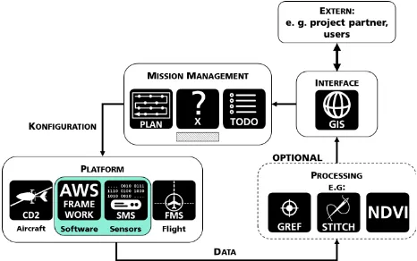
The main system is segmented in three subsystems. The first part is a base system that provides aircraft independent battery power, position data from a high-precision two-channel, two antenna GNSS-receiver as well as true flight level above ground level (AGL) measured using a radar altimeter. Data from this part are forwarded to the two subsystems described below. The second part is the flight management system (FMS). It is essential for navigating the aircraft to a preplanned area and emitting a trigger signal for the sensor system at precalculated trigger points. The FMS software runs on a rugged tablet PC that can easily be mounted in the cockpit or on a kneeboard. The third part consists of the sensor management system (SMS) as well as the custom-developed and integrated sensors. The SMS controls the particular sensors and acquires the data along with further information about position, flight level, incident light and environmental data at a given trigger impulse by the FMS. The tailor-made control and data acquisition application hosted on the SMS is based on our own software framework called AWS. Once configured and started the overall system runs autonomously. Feedback information about the actual state of the system, height information of the radar altimeter as well as a reference image that was taken at the last trigger point are displayed on a status monitor.
Figure 3. Schematic overview of the complete modularized system.
2.2 VIS-RGB Camera
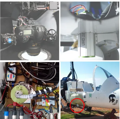
A gimbal mounted, high resolution (36 MP) DSLR Nikon D800e is used to acquire aerial VIS-RGB images (Figure 4). The lens has a fixed focal length of 35mm and is very light sensitive. At a typical flight level of 400 m AGL the swath width is 411 m resulting in a ground resolution of 0.06 m. A custom developed hardware connects the camera with the GNS-system, the FMS as well as the SMS. Therefore a specific image acquisition by a trigger signal is possible and the images are directly georeferenced in meta data and then stored on the camera. A further integration concerning storing the image data into the SMS is planned.
Figure 4. Top left: On-board RGB-VIS camera mounted in a stabilization platform for permanently nadir viewing angle. Top right: Hyperspectral imager UHD 285 integrated in an aircraft (here: CloudDancer2). Bottom left: Inside view of hyperspectral imager UHD 285 integrated in an aircraft (here: Trojan, Wagtail Aviation) owned by a partner situated in South Africa. Bottom right: Outside view of the same configuration in the Trojan gyro.
2.3 Snapshot Hyperspectral Imager UHD 285
The second sensor modality is the Cubert hyperspectral camera UHD 285 (Michels et al., 2014). The advantage of such a system is the direct acquisition of areal hyperspectral image information that eliminates the need of an expensive, high precision IMU that is necessary for image reconstruction from line scanner data. The spectral range of the camera is 450 to 950 nm. The spatial resolution amounts to 2500 (50x50) spectral pixel. Each pixel consists of 125 spectral channels with 14-bit digitization. The integrated panchromatic reference channel has a spatial resolution of 1000 x 1000 pixel. At flying altitudes of 300 m AGL the swath width is about 100 m with a hyperspectral ground resolution of 2 m per pixel.
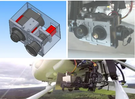
Figure 5. First test flight with VIS-RGB and the hyperspectral imager. A reference orthomosaic was created from the VIS-RGB images. From the acquired hyperspectral data the NDVI was calculated from two 10 nm spectral bands at 670 nm and 800 nm central wavelength (Thenkabail et al., 2002). The resulting NDVI images could only be matched, if possible at all, in several image stripes and were then matched with the drawback of the low spatial resolution of aerial thermal infrared (TIR) images, resulting from low sensor resolution (here: 640x480 pixel) a dual camera setup was developed. The thermal information is acquired by an uncooled microbolometer in the long-wavelength infrared range (LWIR, Allied Vision Pearleye P-030). As a second modality for acquiring high-resolution, well-structured image data a panchromatic (PAN, Allied Vision Mako G-419b) VIS camera was selected. Both sensors are precisely aligned in a custom designed rack that is mounted in a stabilization system (gimbal). After a survey flight the acquired data sets of the two sensors are fused to multi-channel images using the workflow in Weber et al. (2015a). The resulting images can be processed a lot easier with photogrammetric tools as the panchromatic channel is used for image alignment and processing. The resulting transformations can then be applied to the thermal channel.
Figure 6. Top left: CAD drawing of the PanTIR system. Top right: Assembled PanTIR system mounted in a stabilization platform mounted on an aircraft. Bottom: PanTIR system in filter in order to select the requested spectral bands. For precise alignment of the cameras a special rack was designed. A prototype system with four possible channels was created, build up and tested with a three camera setup for NDVI calculations (Thenkabailet al., 2002). Therefore, besides the panchromatic channel, a red channel (670 nm ± 5 nm) and a near-infrared channel (850 nm ± 20 nm) were chosen. Each camera has a resolution of 4 MP. At a flying altitude of 300 m AGL the swath width is about 300 m with a ground resolution of 0.15 m per pixel. not already happened in-flight. If a sensor module is made up of multiple image sensors all image frames taken at the same trigger point are fused to a multi-channel respectively to a multi-dimensional information file (Weber et al., 2015a). The resulting image data can then be orthorectified via photogrammetric software tools and orthomosaics can be generated. In the first instance the software PhotoScan Professional from Agisoft was selected. This tool is based on the structure-from-motion approach (SfM) (Wu, 2013; Westboy et al., 2012).
3. RESULTS
3.1 VIS-RGB Aerial Imaging
Figure 8. Generation of before and after orthomosaics for documentation purposes. Left: Man-made firs bar that divides two habitats of flora and fauna before clearing (September 2013). Right: Cleared area of the former firs bar (May 2014).
3.2 Hyperspectral Imaging (UHD 285)
The hyperspectral imager was tested with the CD2 carrier platform. The system was then used for a test survey of different agricultural sites as well as parts of a national park in South Africa in cooperation with a project partner (GyroLAG). The results of two different survey areas are shown in Figure 9. The first row represents the panchromatic reference channel used for mosaicking process. Based on the hyperspectral data a CIR false color composite (middle) and the NDVI (bottom) were calculated.
Figure 9. Left: Crop field near Potchefstroom, Northwest State, South Africa. Right: Part of the nature reserve Bateleur, Province Limpopo, South Africa, where a believed to be extinct butterfly species was rediscovered (Mecenero et al., 2013).
3.3 Thermal Aerial Imaging (PanTIR)
In advance of a larger surveying campaign in the field of hydrology the performance of the PanTIR imager was tested during several flights. The results of one of those test areas are shown in Figure 10 and Figure 11. The selected area has a size of 6.5 km2 and is situated next to the airfield Dahlemer Binz (Eifel) and contains a stone pit. Compared to the surrounding vegetation artificial structures like dumps of waste material or tarmacs show a well recognisable contrast. This structural variety makes it a suitable thermal test area. At a flying altitude between 1000 and 1200 m the swath width was about 825 m resulting in a ground resolution of 0.4 m for the VIS-PAN channel and 1.3 m for the LWIR channel.
Figure 10. Top: Flight plan of the surveyed area (Steinbruch, Schmidtheim Eifel). Middle: Georeferenced orthomosaic of the panchromatic channel. Bottom: Visualization of the orthomosaic TIR image layer. Both mosaics were rendered with a SfM tool (Agisoft PhotoScan) and then imported in QGIS.
3.4 Multispectral Aerial Imaging (PanX)
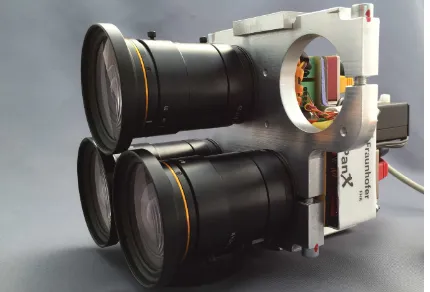
As part of an agricultural survey in South Africa in February 2015 the performance and reliability of a three channel configuration of the PanX system was tested. As described in section 2.5 the system was equipped for NDVI recordings (Figure 12). The operational performance and the amount of acquired images met all expectations. The final results of the survey will be published in a future paper.
Figure 12. Three channel configuration of the PanX system for NDVI imaging.
4. CONCLUSIONS AND FUTURE WORK
The results of several test scenarios show that the gyrocopter is the suitable choice for airborne remote sensing applications in the medium range up to 40 km2 per hour. In combination with a good payload, low operational costs, a high manoeuvrability and operating range, it is able to open the field of remote sensing to a wider circle of potential users like small scientific institutions or small and medium-sized businesses. Moreover it is the ideal carrier platform for developing and testing new sensors like the one described above.
The presented sensor system stands out due to its compact, highly modularized and powerful setup. All sensor modalities of the system were successfully tested and could easily be ported to a second gyrocopter from another manufacturer. A new high-resolution multispectral camera setup with four spectral channels was built and successfully tested on an agricultural survey in a NDVI configuration.
It is planned to expand the four channel multispectral camera setup by two additional channels in order to acquire more spectral information with a single flight. Furthermore the wavelength ranges will be extended to SWIR, allowing the system to be used in a broader field of application. Additionally automatic lens correction routines and atmospheric corrections will be integrated in the software framework of the multi-camera setup.
ACKNOWLEDGEMENTS
The authors thank Allied Vision for kindly providing the Pearleye P-030 camera for free.
REFERENCES
Mecenro, S., Ball, J. B., Edge, D. A., Hamer , M. L., Henning, G. A., Krüger, M., Pringel, E. L., Terblanche, R. F. and Williams, M. C., 2013: Conservation Assessment of Butterflies of South Africa, Lesotho and Swaziland: Red List and Atlas. Saftronics (Pty) Ltd. and the Animal Demographic Unit, S.478.
Michels, R., Liebsch, S. and Graser, R., 2014: Snapshot-Hyperspektroskopie. Photonik 01/2014, S. 36-38
Miraliakbari, A., Hahn, M. and Engels, J., 2010. Development of a Low-cost Sensor System for Use on Gyrocopters. Canadian Geomatics Conference 2010 and ISPRS Com. I Symposium, International Archives of the Photogrammetry, Remote Sensing and Spatial Information Sciences, Vol. XXXVIII, Part 1, 7
Thenkabail, P. S.; Smith, R. B. and De Pauw, E.; 2002: Evaluation of narrowband and broadband vegetation indices for determining optimal hyperspectral wavebands for agricultural crop characterization, Photogrammetric Engineering and Remote Sensing, 68 (6), S. 607-622
Weber, I., Jenal, A., Kneer, C. and Bongartz, J., 2015a. PanTIR – A dual camera setup for precise georeferencing and mosaicing of thermal aerial images. Proceedings on Workshop of Photogrammetric Image Analysis 2015, Munich, Germany.
Weber, I., Kneer, C., Jenal, A. and Bongartz, J., 2015b. Einsatz einer bildgebenden Hyperspectralkamera in einem Tragschrauber. DGPF conference proceedings 24/2015, Cologne, Germany.