A SMARTPHONE-BASED 3D PIPELINE FOR THE CREATIVE INDUSTRY
–
THE REPLICATE EU PROJECT
–
E. Nocerino
1, F. Lago
1, D. Morabito
1, F. Remondino
1, L. Porzi
2, F. Poiesi
2, S. Rota Bulo’
2, P. Chippendale
2,
A. Locher
3, M. Havlena
3, L. Van Gool
3, M. Eder
4, A. Fötschl
4, A. Hilsmann
5, L. Kausch
5, P. Eisert
51 3D Optical Metrology (3DOM) unit, Bruno Kessler Foundation (FBK), Trento, Italy <nocerino><lago><morabito><remondino>@fbk.eu
2 Technology of Vision unit, Bruno Kessler Foundation (FBK), Trento, Italy <porzi><poiesi><rotabulo><chippendale>@fbk.eu
3 Computer Vision Lab, ETH Zurich, Switzerland
<alocher><michal.havlena><vangool>@vision.ee.ethz.ch
4 Wikitude GmbH, Salzburg, Austria <markus.eder><andreas.foetschl>@wikitude.com
5 HHI Fraunhofer, Berlin, Germany
<anna.hilsmann><lisa.kausch><peter.eisert>@hhi.fraunhofer.de
Commission II
KEY WORDS:
3D reconstruction, Smartphone, Creative industry, REPLICATE
ABSTRACT:
During the last two decades we have witnessed great improvements in ICT hardware and software technologies. Three-dimensional content is starting to become commonplace now in many applications. Although for many years 3D technologies have been used in the generation of assets by researchers and experts, nowadays these tools are starting to become commercially available to every citizen. This is especially the case for smartphones, that are powerful enough and sufficiently widespread to perform a huge variety of activities (e.g. paying, calling, communication, photography, navigation, localization, etc.), including just very recently the possibility of running 3D reconstruction pipelines. The REPLICATE project is tackling this particular issue, and it has an ambitious vision to enable ubiquitous 3D creativity via the development of tools for mobile 3D-assets generation on smartphones/tablets. This article presents the REPLICATE project’s concept and some of the ongoing activities, with particular attention being paid to advances made in the first year of work. Thus the article focuses on the system architecture definition, selection of optimal frames for 3D cloud reconstruction, automated generation of sparse and dense point clouds, mesh modelling techniques and post-processing actions. Experiments so far were concentrated on indoor objects and some simple heritage artefacts, however, in the long term we will be targeting a larger variety of scenarios and communities.
1. INTRODUCTION
Ten years ago, the first touchscreen smartphones (Apple iPhone) came on the market and a social revolution started. Nowadays, smartphones enable us to perform many actions, such as communication, photography, navigation, localization, paying, etc. Above and beyond these everyday actions, 3D imaging is emerging as a new mobile-based technology that can exploit the significant improvements in camera resolution, processing power, and visualization methods to create 3D models by anyone. Although smartphone camera optics currently lack sufficient quality for high-precision imaging tasks, they are light, portable and thus with us most of the time which will inevitably stimulate the spontaneous capture of creative 3D content in situ. In particular, the creative industries (VR, AR, 3D printing, design, etc.) will benefit from such ad-hoc generation for their artistic creations. Moreover, as 3D content is being heavily requested by emerging VR/AR applications, very soon there will be an insatiable demand for new forms of diverse 3D assets, thus the need for revolutionary constructor tools. 3D reconstructions and printing are sparking the interest of citizens and logical the consumer market, trigger a new revolution in production methods. Many ICT companies are addressing the implications of relatively low-cost digitally “replicating” methods, and it is
this market which the REPLICATE project is directly addressing. The EU funded H2020 REPLICATE project started in January 2016, will run for three years and addresses the above mentioned issues and aims (www.3dharvest.com/Replicate/index.html). REPLICATE will bring the entire image-based 3D reconstruction pipeline (based on photogrammetry and computer vision methods) onto smartphones and create a set of tools to enable a user to produce 3D models that are compliant and useful, particularly for – but not limited to – the creative industry.
2. THE REPLICATE PROJECT
The project has the vision of enabling ubiquitous creativity through the development of a 3D asset generation tool for mobile devices. In a nutshell, REPLICATE aims to:
Exploit the rapidly advancing area of mobile 3D imaging methods and mobile/Cloud computation to develop technologies needed for efficient, low-cost and high-qualit y 3D content generation.
Generate detailed and complete 3D models from diverse scenarios, semantically decompose these models, enable their re-use, facilitate their simple modification, increase The International Archives of the Photogrammetry, Remote Sensing and Spatial Information Sciences, Volume XLII-2/W3, 2017their ‘searchability’ through better tagging and - most importantly - make all content industry compliant.
Stimulate user interactions with 3D content, offering better engagement with the creative process and stimulate multi-user creative collaborations with the 3D content by making the entire process a fun experience for everyone involved.
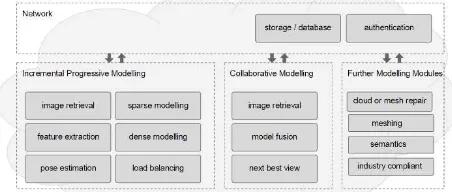
Maximize social and economic impact with the goal of achieving sustainable growth in the creative industry sector. REPLICATE will thus bring the entire image-based 3D reconstruction pipeline onto smartphones and tablets. Clusters of images and short videos will be utilized. To enable the exploitation of 3D reconstruction techniques and the possibility to on-the-fly add new images for a 3D model reconstruction when they become available, processing is being performed partly on the mobile device and partly in the Cloud (Fig. 1).Figure 1: The overall architectures and functions of REPLICA T E image-based 3D modelling pipeline.
2.1 Relate d works
There are various researches working on the topic of 3D reconstruction from mobile devices, like smartphones. The topic needs to address issues like real-time processing, incremental adjustment, dense 3D reconstruction and web-based processing. Some smartphones are beginning to incorporate 3D depth sensors but the vast majority only contain monocular cameras. In the case of active depth sensors, devices like Google Tango (Diakite and Zlatanova, 2016), Pico Flexx (PMDTech, 2017) and PiCam (Venkataraman et al., 2013) were explored for 3D reconstruction purposes. On the other hand, for a purely video- and image-based approach, pioneering work on real-time 3D reconstruction has come from Pollefeys et al. (2008), Vogiatzis and Hernandez (2011), Wendel et al. (2012) and Pradeep et al. (2013) whereas works on real-time tracking and mapping were presented in Klein and Murray (2009), Stuehmer et al. (2010) and Newcombe et al. (2011). All of the aforementioned methods require high-end desktop CPU/GPU and cannot function effectively on smartphones.
Web-based 3D reconstruction applications were presented in Vergauwen and Van Gool (2006), Heller et al. (2015) as well as with the well-known Microsoft Photosynth (Snavely et al., 2008). Commercially there exist some pure image-based applications (e.g. Scann3D – http://scann3d.smartmobilevision.com/, 3D Scanner, etc.) that promise to create 3D models of people or objects using a mobile device. The 3D reconstruction is performed on a cloud server or directly on the phone based on videos or images.
In general, real-time camera pose estimations, depth-map fusion and 3D scene reconstruction are still far away from being achieved on mobile devices purely using images. Tanskanen et al. (2013) and Kolev et al. (2014) presented 3D reconstruction methods for mobile phones using monocular videos as an input.
In their approach, for each key-frame, a depth map is estimated in a multi-resolution approach to obtain sufficient speed and robustness, although real-time performance could not be achieved. Some other works deal with mobile phone with embedded depth sensors (Schops et al., 2015) or with RGBD sensors and related software packages (Reconstructme, KinectFusion, Skanect, etc.).
3. IMAGE-BASED 3D RECONSTRUCTION WITH SMARTPHONE DEVICES
The goal here is to develop a collection of interlinked routines and GUIs that would enable a user to bring together either single images or a video sequence of an object of interest and derive a textured 3D model. More specifically, the workflow includes:
a mobile app that will interactively guide a single, or multiple users through the image acquisition process and all of the subsequent processing steps (*);
a SLAM algorithm - running on the smartphone - to track device-pose in real-time and to create a fast visual-feedback via a semi-dense point cloud (*);
automated key-frame selection - running on the smartphone - to extract the most pertinent and content rich frames for the 3D reconstruction procedure;
an incremental SfM routine - running in the Cloud - to derive sparse 3D point clouds;
a hierarchical progressive multi-view stereo algorithm - running in the Cloud in case of low-performing mobile devices – to derive dense 3D point clouds;
a 3D reconstruction server and an API viewer set up through an HTML5 web interface to run the previously mentioned functions;
a routine for automatic point cloud repairing - running on the Cloud;
detection of planar surfaces and straight lines to constrain and aid in better surface-model generation;
a routine for polygonal model generation (meshing) and refining;
a routine for mesh repairing and simplification - running in the Cloud;
functions for texture extraction and optimization;
functions for semantically decomposing 3D models (*);
a GUI through which the 3D reconstructed models can be accessed for user visualization and interaction (*);
a GUI to enable collaborative 3D reconstructions, i.e. partial results and inputs from different devices and users are processed by the cloud infrastructure and then fed back to the adaptive user guidance task (*).Some of these functions were developed within the first year of the project, whereas others (*) are still to be realized. Some of the aforementioned tasks run on the smartphone device whilst other functions need to be performed on the Cloud. One of the major challenges being faced in implementing a Cloud-based 3D reconstruction solution, is the bandwidth used to send the mobile -captured images to the Cloud-server for the intense photogrammetric processing. Ideally, clients should not consume excessive wireless bandwidth, minimising communications between the mobile device and the server.
Figure 2: Detail workflow and functions of REPLICATE among Cloud and smart device.
3.1 Image acquisitions and pre -processing
A mobile app enables the user to acquire a sequence of frames, extracting only the best ones that are deemed potentially useful for the cloud 3D reconstruction algorithms. This algorithm (Fig. 3), works on the smartphone as the user is moving the device around an object.
Figure 3: Block diagram of the key-frame selection algorithm. T is a threshold applied to the sharpness value. M is the interval of good matches to select the frame.
Selection is based on the computation of a frame’s sharpness and also the number of new features present (Sieberth et al., 2016). Hence, a ‘content rich’ frame should be sharp (i.e. in focus and with no motion blur) and it should contain new visual information about the object. Newness is quantified by comparing current feature points with those extracted from previous frames. A sharp frame provides edge-detection results that have intensity gradients with well-defined discontinuities, whereas a blurred frame has instead flatter/smoother gradients. The quantification of the sharpness, S, involves six steps: (i) convert the RGB image to HSV space, (ii) apply low-pass filter (e.g. Gaussian) to H-channel image, (iii) apply high-pass filter (e.g. Laplacian) to the low-pass filtered image, (iv) apply low-pass filter to the original H-channel image and to the high-pass filtered image, (v) compute the difference image between these two filtered images and (vi) compute the standard deviation of the difference. The Laplacian emphasises the intensity values in the filtered image, thus it quantifies the discontinuities (edges) in the original. Following these steps, frames with a value of sharpness below a threshold are discarded while the others are further processed to compute their visual overlap with previous frames. The quantification of the overlap is calculated for pairs of frames and by using ORB keypoints (Rublee et al., 2011). The image overlap is inferred by matching descriptors among adjacent frames based on the Hamming distance. Given a buffer, B, of descriptors to summarize what “has been seen”, a frame is only kept if the Hamming distance is below a certain threshold (i.e. the number of good matches is between 10 to 45 percent). If no frames were selected for a certain minimum interval of time, a frame is
transmitted anyway. Consequently, its features are used to update B.
3.2 Pose estimation and s parse point cloud
The system’s geometric processing of the selected frames (SfM) is based on the publicly available libraries of Sweeney (2015) and can run on a single CPU. Feature points and descriptors are extracted from images using various operators. Descriptors are then indexed into a pre-trained visual vocabulary. We use a 1M word vocabulary trained on the Oxford 5k dataset (Philbin et al., 2007) with approximate k-means clustering. Every descriptor gets quantized as a visual word (or “label”) and an inverted file is gradually built. Using the inverted file, a retrieval process based on the tf-idf scoring (Sivic and Zisserman, 2003) is carried out. Up to 50 similar images are retrieved from the already-indexed images of the scene, providing that they have a non-zero score. All the retrieved images that are deemed to be relevant for the view-pairs are passed to the ‘relative orientation computation’ block, based on a RANSAC / LO-SAC framework. View-pairs having at least 30 positive matches are added to a view-graph where the nodes are the images and the edges represent the matches between the images. In order for the user to have an instant feedback on the reconstruction process, an incremental bundle-adjustment algorithm estimates the poses of all cameras and reconstructs the scene (Fig. 4) by using the view-pairs and relative geometries.
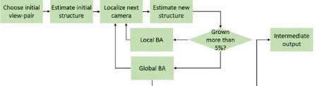
Figure 4: The main steps of the incremental bundle adjustment to derive camera poses and a sparse 3D point cloud.
The algorithm starts by selecting an initial view-pair as the starting point and progressively links more and more views to the existing reconstruction (Agarwal and Mierle, 2012). Selection criteria for the initial view-pairs are the number of matches as well as the sufficiency of the baseline among the two views. The structure of the two-view estimation is computed and the next camera image (i.e. the one that observes the greatest number of already-estimated 3D points) is localized using a Perspective-Three-Point P3P algorithm, i.e. the state-of-the-art solution to determine position and orientation of a camera given 3 image-to-The International Archives of the Photogrammetry, Remote Sensing and Spatial Information Sciences, Volume XLII-2/W3, 2017
world-point correspondences. Then new points are triangulated and a local or global bundle-adjustment is executed. Intermediate results are made available to the user after each global bundle -adjustment step, which are utilised to give direct feedback. This pipeline is quite sensitive to the initial view-pair selection. In the REPLICATE scenario, the initial views are determined by the user (i.e. the first captured views) and are not necessarily optimal views. The 3D reconstruction could fail in the case of bad initialization. Therefore, the approach computes a threshold of the ratio between successfully reconstructed images and images which could not be added to the scene. If this “condition of failure” is not passed, the reconstruction process is started again with another initial view-pair.
3.2.1 SLAM pose estimation
A sub-module enables the system to estimate, in real-time, the pose of the mobile device with respect to the object being scanned, on a smartphone (Fig. 5). It associates additional pose information to the acquired images, potentially useful for the reconstruction engine, but it is primarily exploited for the overlaying of real-time AR feedback (e.g. which section still need to be scanned) to the user. Considering the project use-cases, as well as the restrictions implied by smartphone platforms, the module is based on the approach by Mur-Artal and Tardós (2015) which is robust to large camera motion. The module needs further refinement to decrease processing power demands, exploit the CPU and ARM architecture on smartphones, and to handle multi-resolution images.
Figure 5: Overview of the SLAM module implemented on the smartphone device fir the real-time estimation of camera poses and sparse point cloud.
3.3 Multi-view ste reo and dense point cloud
Nowadays, dense image-matching procedures – often called Multi-View Stereo (MVS) - are generally unavoidable if you wish to deliver visually-pleasant results to the user and serve as a robust input for the successive meshing stage. Considering the REPLICATE scenarios and constraints, an instant feedback of the 3D-reconstruction process is needed. MVS algorithms are usually executed as simple batch-processes with long processing time. To decrease this time delay, REPLICATE employs a hierarchical progressive Multi-View Stereo algorithm (Locher et al., 2016a) which derives more accurate and denser point clouds as time goes by. This algorithm takes the camera parameters and 3D tie-points, and generates an initial set of 3D patches that are spatially organized into a dynamic octree. These patches are then sent to a processing queue for insertion into a processing loop that consists of three circular steps:
expansion: all patches are expanded along their surfaces using a planarity-prior and then placed into neighbouring cells. Afterwards, patch normals and positions are optimized using a
nonlinear optimization so that the normalized cross-correlation between all patch projections into visible images (photo consistency) is maximized. Patches that are successfully optimized are added to the octree, whereas the failing ones are discarded;
filte ring: the neighbourhood of all patches is analysed and patches with less than three valid neighbours in their close neighbourhood or with normals that do not agree on neighbourhood normals are discarded. Using the octree structure, this can be executed efficiently;
branching: patches are split into finer resolution elements to increase the point cloud resolution over time. Typically, the patch gets split into four smaller patches which are then optimized using the same nonlinear optimization as in the expansion step. Successful patches are added to the sub-cell of the old patch, which creates a multi-resolution output. A priority-based scheme is employed to drive the reconstruction forward as the patches becomes individually available in the processing loop. The processing priority depends on (i) patch resolution (the finer is the resolution, the less is the priority), (ii) step priority (to guarantee that all patches are expanded before they get filtered and branched) and (iii) user defined prior (e.g. steer the reconstruction into regions of interest).
The aforementioned progressive MVS method delivers a progressively growing dense point cloud output well-suited to provide continuous user feedback. Because the reconstruction process runs in a loop, the user can retrieve denser resolution models the longer she/he waits. The reconstruction itself stops automatically when a user pre-defined resolution is reached, or when all patches reached the finest resolution. Unfortunately, it cannot handle the incremental addition of new images (in the case of collaborative reconstructions). Therefore, a dense point cloud should be recomputed from scratch once a change in the underlying image network has occurred (i.e. update in the sparse point cloud pipeline).
The REPLICATE pipeline will soon include the MVS algorithm presented in (Locher et al., 2016b): with the algorithm being able to adapt to changes between consecutive sparse 3D point clouds and propagate them to the corresponding dense point cloud. This will enable us to reuse and update already computed 3D point clouds, leading to a one-order-magnitude speed-up whilst maintaining model quality.
3.4 Point cloud editing
Despite the robust procedures for dense point cloud generation, the generated point clouds may still present unwanted artefacts, due to unfavourable environment conditions (e.g. poor lightin g), non-cooperative object materials (e.g. shiny surface, homogeneous textures, etc.), image quality, image network, etc. A user-guided point cloud editing and improving approach has thus been developed to solve these issues (Fig. 6). Its functions include: (i) an automatic and iterative identification and subsequent elimination of point sub-clusters separated from the main ‘body’ of the point cloud (i.e. the identification and elimination of the disconnected components or islands), (ii) the elimination of duplicate points, which involves the filtering of those points that are closer to the median point cloud resolution and (iii) a point cloud down-sampling, which uses a user-defined parameter to get a smaller and lighter point cloud, enabling fast web visualization.
We are currently developing features for colour-based point selection and an interactive tool to empower the user to interactively select which islands to keep and/or erase. So far, the module enables us to handle and process up to 10 million points on a smartphone, however, a more efficient approach is under development.
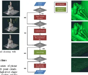
Figure 6: Sequential editing steps of the point cloud cleaning with examples.
3.5 Dete ction of planar surfaces and straight lines
A module is under development for the identification of planar surfaces and/or straight lines in unstructured 3D point clouds. This function will deliver useful knowledge and high-level shape information valuable for the point cloud repairing module and the mesh-generation module. Preliminary experiments have been performed by modifying the method presented in (Bodis-Szomoru et al., 2016). This module will run on the cloud.
3.6 Mesh generation
The module firstly converts the available dense point cloud into a polygonal surface model (mesh) and secondly applies an image-based refinement. The mesh is created using the Poisson reconstruction method, providing correctly estimated surface normals. As the normal direction might not be present in photogrammetric-based point clouds, a visibility tool is being considered in order to ensure correct normal orientation. Since the surface points directly arise from matched image-features, and, as we know from which camera a (3D) point has been observed, the normal vectors for these points cannot point away from any of the cameras. With this constraint, the algorithm detects and flips wrongly-estimated normals and ensures optimal results from the Poisson-based surface reconstruction. Once, the mesh has been created from the 3D point cloud, a shape refinement based on Blumenthal et al. 2014 is followed. With this approach, small surface details can be added, holes filled, and the overall geometry enhanced by considering surface priors and information on planar surfaces and straight lines.
3.7 Mesh editing
The user is guided through sequential automated steps - running on the Cloud - to (i) eliminate triangles whose edge lengths are bigger than the average mesh resolution and (ii) discard isolated mesh components or islands, as well as self-intersecting and non-manifold triangles (Fig. 7). The user can then fill the holes in a semi-automatic way: the simpler and smaller holes are filled automatically, whereas more complex holes require user interaction. In a future implementation, geometric information coming from the identification of geometric primitives (planes, cylinders, spheres, etc.) will be considered to make the hole -filling procedure faster and more robust. Moreover, a re-topology procedure to harmonize all polygonal faces and a mesh-simplification tool will be available.
Figure 7: Mesh editing module and examples of the editing.
3.8 Te xture creation and optimization
The texture extraction tool uses all available images to create an optimal texture for the reconstructed surface-mesh. The tool is based on non-linear optimization that minimizes the difference between the mesh texture and all input images. Because the appearance of an object in an image is not only dependent on its texture but also on the scene illumination and camera exposure, these two quantities are accounted for as additional parameters to the texture optimization. The scene illumination is represented globally by a linearly parametrized diffuse illumination map. The camera exposure is a nonlinear gamma function that is applied to each individual image and is defined by a set of parameters per view.
3.9 Semantic decomposition
The final aim of REPLICATE is to offer 3D models with semantic meaning. To meet this goal, a decomposition of the 3D-meshes into semantic segments - running on the Cloud - will be implemented within the REPLICATE workflow. So far, three methods have been investigated:
a supervised approach: semantic categories are learned from a dataset of annotated meshes (or images) and the trained model (by means of machine learning and deep convolutional neural networks method) is used to provide a semantic segmentation of a mesh;
an unsupervis ed approach: the mesh is automatically partitioned into segments based on a user-provided parametrization of the algorithm and exploiting the intrinsic geometry of the 3D model;
an inte ractive segmentation approach: the user is actively involved in the segmentation loop by guiding the extraction of segments via feedback signals.
4. OUTDOOR AND INDOOR EXAMPLES
Figures 8 and 9 show two examples of datasets acquired and processed through the REPLICATE workflow on a mobile phone The International Archives of the Photogrammetry, Remote Sensing and Spatial Information Sciences, Volume XLII-2/W3, 2017
device. Selected frames were processed by the dedicated REPLICATE server to obtain a sparse and dense 3D point cloud as well as a textured polygonal model. The visualization of this model is currently performed via a HTML5 website with an integrated WebGL interface that facilitates its navigation, exploration and analysis.
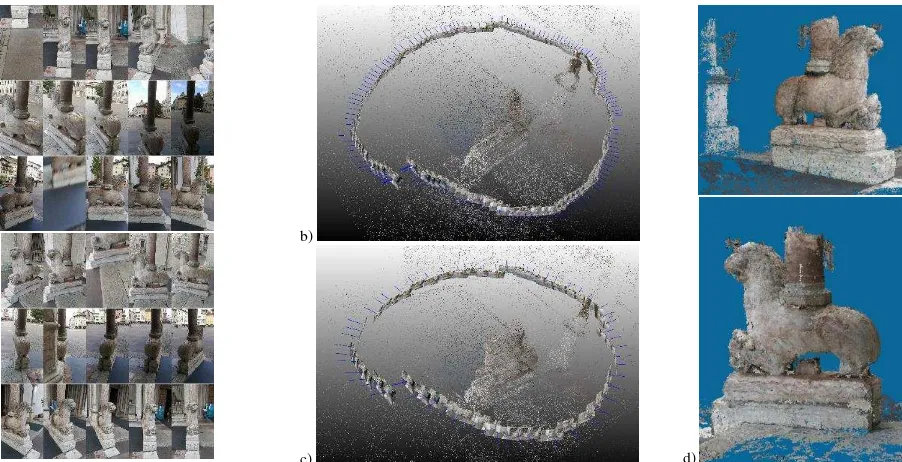
In the outdoor scenario (Fig. 8), a video sequence of a lion-shaped base column at the entrance of Trento’s Cathedral has been acquired. Two different processes were performed: in the first case, 151 frames were uniformly extracted from the entire video sequence whereas, in the second, the best frame selector procedure (Section 3.1) was used, providing a reduced set of 64
frames. The results look visually similar, however, the latter case uses less than half of the frames. The hierarchical progressive MVS algorithm (Section 3.2) is then applied to derive a dense point cloud of the lion-shaped base column.
For the indoor case study (Fig. 9), results are reported for the meshing and semantic decomposition of a small object, a 10 cm long mandrill-shaped doll. This object can initially be segmented from the background to become an independent element and in principle included in the list of assets that a user can re-use in other contexts (e.g. VR game). This object can be further decomposed into parts (e.g. legs, torso, head) that a user can use for additional edits.
a)
b)
c)
d)
Figure 8: Example of the REPLICATE workflow for an outdoor scenario for image selection, camera pose estimation and dense point cloud generation. From the acquired video, two different processes have been performed: a uniform extraction of the frames (151 – Fig. 8b) and the best frame selector procedure (Section 3.1 - Fig. 8c). The final dense point cloud contains some 500K points.
Figure 9: Example of REPLICATE workflow on a small indoor object: image network, derived mesh, textured 3D model and semantically segmented result.
5. CONCLUSIONS
The article presented an overview about the EU H2020 REPLICATE project and reported the main features and tools developed during its first year. The project, funded within an EU ‘Research and Innovation Action’ to support creative processes in the creative industries, aims to develop a usercentric, mobile -based, 3D acquisition tool to transform real-world objects and scenes into new forms of digital creative assets. With this in mind, the scientific partners are developing algorithms and tools to adapt and optimize the 3D reconstruction workflow for mobile devices with intuitive user interaction. To minimise bandwidth demands, a sub-set of the best and most meaningful frames are sent to the cloud for incremental bundle adjustment and dense image matching procedures. User-guided for the point cloud editing and mesh editing tools is under way as is the integration
of real-time pose estimation to create a user-centric modelling procedure. In the following two years, AR/VR tools will be deployed to enable better user interactions, improving engagement and collaboration with 3D content, offering an attractive co-creativity and immersive environment.
ACKNOWLEDGMENTS
This research has received funding from the European Union's Horizon 2020 research and innovation programme under grant agreement number 687757.
REFERENCES
Agarwal, S., Mierle, K., 2012: Ceres solver: Tutorial & reference. Google Inc., http://ceres-solver.org [last access: January 22nd, 2017]
Blumenthal-Barby, D., Eisert, P., 2014: High-resolution depth for binocular image-based modelling, Computers & Graphics , Vol. 39, pp. 89-100.
Bodis-Szomoru, A., Riemenschneider, H., Van Gool, L., 2016: Efficient edge-aware surface mesh reconstruction for urban scene. Int. Journal of Computer Vision and Image Understanding
Diakite, A., Zlatanova, S., 2016: First experiments with the Tango tanglet for indoor mapping. ISPRS Annals of Photogrammetry, Remote Sensing and Spatial Information Sciences, Vol. III-4, pp. 67-72
Heller, J., Havlena, M., Jancosek, M., Torii, A., Pajdla, T., 2015: 3D reconstruction from photographs by CMP SfM web service. Proc. IAPR International Conference on Machine Vision Applications (MVA), pp. 30-34
Klein, G., Murray, D., 2009: Parallel tracking and mapping on a camera phone. Proc. ISMAR, pp. 83-86
Kolev, K., Tanksanen, P., Speciale, P., Pollefeys, M., 2014: Turning mobile phones into 3D scanners. Proc. IEEE CVPR 2014
Locher, A., Perdoch, M., Van Gool, L., 2016a: Progressive prioritized Multi-View Stereo. Proc.IEEE CVPR
Locher, A., Havlena, M., Van Gool, L., 2016b: Progressive 3D Modelling all the way. Proc. IEEE Int. Conf. on 3D Vision
Conference on 3D Vision. Vol. 1. IEEE, 2016
Mur-Artal, R., Tardós, J.D., 2015: Probabilistic semi-dense mapping from highly accurate feature-based monocular SLAM. Proc. Robotics: Science and Systems
Newcombe, R. A., Lovegrove, S. J., Davison, A. J., 2011: DTAM: Dense tracking and mapping in real-time. Proc. IEEE ICCV, pp. 2320-2327
Philbin, J., Chum, O., Isard, M., Sivic, J., Zisserman, A., 2007: Object retrieval with large vocabularies and fast spatial matching." Proc. IEEE CVPR
PMDTech, 2017: http://pmdtec.com/picoflexx/ [last access: January 22nd, 2017]
Pollefeys, M., Nister, D., Frahm, J.-M., et al., 2008: Detailed real-time urban 3d reconstruction from video. Int. J. Computer Vision, Vol. 78(2-3), pp. 143-167
Pradeep, V., Rhemann, C., Izadi, S., Zach, C., Bleyer, M., Bathiche, S., 2013: Monofusion: Real-time 3D reconstruction of small scenes with a single web camera. Proc. ISMAR, pp. 83-88
Rublee E., Rabaud, V., Konolige, K., Bradski, G., 2011: ORB: an efficient alternative to SIFT or SURF. Proc. IEEE ICCV Schops, T., Sattler, T., Hane, C., Pollefeys, M., 2015: 3D modeling on the go: Interactive 3d reconstruction of large-scale scenes on mobile devices. IEEE Proc. 3D Vision (3DV), pp. 291-299
Sieberth, T., Wackrow, R., Chandler, J.H., 2016: Automatic detection of blurred images in UAV image sets. Journal of Archaeological Science, Vol. 122, pp. 1-16
Sivic, J., Zisserman, A., 2003: Video Google: A text retrieval approach to object matching in videos. Proc. IEEE ICCV
Snavely, N., Seitz, S., Szeliski, R., 2008: Modeling the world from Internet photo collections. International Journal of Computer Vision, Vol. 80(2), pp. 189-210
Stuehmer, J., Gumhold, S., Cremers, D., 2010: Real-time dense geometry from a handheld camera. Proc. DAGM Pattern Recognition, pp. 11-20
Sweeney, C., 2015: Theia multiview geometry library: Tutorial & reference. UCSB, USA, http://www.theia-sfm.org [last access: January 22nd, 2017]
Venkataraman, K., Lelescu, D., Duparré, J., et al., 2013: PiCam: An ultra-thin high performance monolithic camera array. ACM Transactions on Graphics, Vol. 32(5)
Vergauwen M., Van Gool, L., 2006: Web-based 3D reconstruction service. Machine Vision Applications, Vol. 17, pp. 411-426
Vogiatzis G., Hernandez, C., 2011: Video-based, real-time multi-view stereo. Image Vision Computing, Vol. 29(7), pp. 434-441
Tanskanen, P., Kolev, K., Meier, L., Camposeco, F., Saurer, O., Pollefeys, M., 2013: Live metric 3D reconstruction on mobile phones. Proc. IEEE ICCV
Wendel, A., Maurer, M., Graber, G., Pock, T., Bischof, H., 2012: Dense reconstruction on-the-fly. Proc. IEEE CVPR, pp. 1450-1457