A GEOMETRIC PROCESSING WORKFLOW FOR TRANSFORMING REALITY-BASED
3D MODELS IN VOLUMETRIC MESHES SUITABLE FOR FEA
S. Gonizzi Barsanti*, G. Guidi
Department of Mechanical Engineering – Politecnico di Milano (sara.gonizzi, gabriele.guidi)@polimi.it
Commission II
KEY WORDS: Mesh Processing, Surface Mesh, Volumetric models, Structural Analysis, FEA
ABSTRACT:
Conservation of Cultural Heritage is a key issue and structural changes and damages can influence the mechanical behaviour of artefacts and buildings. The use of Finite Elements Methods (FEM) for mechanical analysis is largely used in modelling stress behaviour. The typical workflow involves the use of CAD 3D models made by Non-Uniform Rational B-splines (NURBS) surfaces, representing the ideal shape of the object to be simulated. Nowadays, 3D documentation of CH has been widely developed through reality-based approaches, but the models are not suitable for a direct use in FEA: the mesh has in fact to be converted to volumetric, and the density has to be reduced since the computational complexity of a FEA grows exponentially with the number of nodes. The focus of this paper is to present a new method aiming at generate the most accurate 3D representation of a real artefact from highly accurate 3D digital models derived from reality-based techniques, maintaining the accuracy of the high-resolution polygonal models in the solid ones. The approach proposed is based on a wise use of retopology procedures and a transformation of this model to a mathematical one made by NURBS surfaces suitable for being processed by volumetric meshers typically embedded in standard FEM packages. The strong simplification with little loss of consistency possible with the retopology step is used for maintaining as much coherence as possible between the original acquired mesh and the simplified model, creating in the meantime a topology that is more favourable for the automatic NURBS conversion.
1. INTRODUCTION
1.1 Overview
In order to achieve diagnostic studies aiming at understanding the level of decay of Cultural Heritage for selecting the appropriate preservation methods and materials, a scientific base for allowing correct interventions would be fundamental. However, it’s always difficult to predict how a historical object or structure, built up to a few thousand years ago, will suffer for environmental agents such as earthquakes, pollution, wind and rain, or human factors like constructions in the surroundings, vehicular traffic, or heavy tourism. Conservation of Cultural Heritage is a key topic and structural changes and damages can affect the structural behaviour of Cultural Heritage artefacts and buildings. Considering that the application of technologies can help in preserving, conserving and restoring ancient structures, it is mandatory to find the best pipeline to produce the correct analysis. The use of Finite Elements Methods (FEM) for mechanical analysis (also known as Finite Element Analysis or FEA), is largely used in modelling stress behaviour. The typical workflow of such analysis involves the use of CAD 3D models made by Non-Uniform Rational B-splines (NURBS) surfaces, representing the ideal shape of the object to be simulated (Höllig, 2003). The major FEA packages has meshing modules capable to transform a NURBS model, made only of its exterior surfaces, to a volumetric mesh, which differently from a surface mesh typically generated with 3D capture methods, has nodes distributed both on the exterior surface and into the interior volume, connected each other by elementary volumes such as tetrahedron, pyramids, prisms or hexahedral. This workflow is appropriate in the mechanical field, where a physical element to
*
Corresponding author.
be simulated is very close to its ideal drawing within strict tolerances. Conversely, when applied to 3D models of Cultural Heritage (CH) objects or structures, often altered by the time passed since their original creation, the representation with a schematic CAD model may introduce an excessive level of approximation leading to wrong simulation results.
Nowadays, 3D documentation of CH has been widely developed through active sensors or passive approaches like photogrammetry, but the models, formed by the exterior surfaces of the objects captured at high resolution and therefore represented by millions of polygons, are not suitable for a direct use in FEA. The mesh has in fact to be converted from superficial to volumetric, and the density has to be reduced since the computational complexity of a FEA grows exponentially with the number of nodes representing the simulated object.
Few preliminary experiments have been done on real CH structures digitized with active or passive methods, whose models have been processed for simulating stress behaviour and predicting damage to artefacts considered critical within the field of conservation. The results are very promising but a few issues have been made evident: a) the way for obtaining a volumetric mesh suitable for FEA from the raw 3D data is not yet clearly defined and may greatly influence the final result, b) the balance between geometric resolution and confidence level of the simulated results is often not compliant with the shape of a 3D model originated by a 3D acquisition process.
The focus of this paper is to present a new method based on a strong simplification of the mesh associated to a topological rearrangement of it. Such process aims at generating the most accurate 3D representation of a real artefact/scenario from highly accurate 3D digital models derived from image-based and range-based techniques, maintaining the accuracy of the
resolution polygonal models in the solid meshes that have to be created for FEA. In addition, the proposed process keeps into account the suitability of the simplified mesh to be converted in a set of NURBS surfaces through an automatic procedure. This allows producing volumetric models of a Cultural Heritage object or structure maximizing the closeness of the resulting NURBS model with the acquired one, and in the meantime minimizing the number of NURBS patches required for describing it. The approach here proposed is based on a wise use of retopology procedures, coupled with a transformation of a simplified and retopologized model to a mathematical model made by NURBS surfaces, close as much as possible to the real shape, but suitable to be transformed in reasonably complex volumetric 3D models through standard FEM packages. This paper validates such approach using a laboratory specimen and a little sculpture as test objects, reprocessing the same original data with a standard simplification approach and the proposed one.
This methodology can be useful for experts in the field of conservation of CH as archaeologists, architects, restores, structural engineers, considering that the lack of funding usually influence the restoration’s interventions. A proper pipeline can help in finding the probable causes for future problems; therefore, carrying out the necessary interventions, will allow a more effective conservation of the structure.
1.2 State of the art
By analysing the previous works in the field, different approaches have been followed until now for generating the volumetric mesh from the acquired 3D point cloud: a) redrawing with a CAD modeller a new surface model following the superficial mesh originated by the acquired 3D cloud; b) using directly the triangular mesh generated by the default 3D capturing pipeline as starting point for generating a volumetric model; c) generating a volumetric mesh from the point cloud originated by the 3D digitization process with no preliminary surface meshing. The first approach has been used in several applications and seems a kind of standard approach to the problem. In the literature there are example for simulating the behaviour of an ancient masonry bridge in Spain (Riveiro et al., 2011), the Trajan's Markets (Brune and Perucchio, 2012), an historic tomb in Turkey (Erkal and Ozhan, 2014) or a church in central Italy after an earthquake (Oreni et al., 2014). In some cases, the reconstructed mathematical model has been refined with the insertion of limited patches of reality-based superficial meshes (Zvietcovich et al., 2014). If this procedure, with all its accuracy limitations, can be applied to CH buildings because the geometry of the structure can be replicated through a CAD drawing using profiles, cannot be instead used for statues, whose geometry is more complex and that cannot be simplified through elements as bean, truss or shell, used for the modelling in FEA. The second approach has a range of slightly different methods: i) bare simplification of the triangular surface mesh before converting it in a volumetric one, that may give significant deviations between the actual shape and the simulated one (Riccardelli et al., 2014); ii) the simplified description of the shape through a set of profiles that are then discretized for generating a limited number of nodes, for creating a reliable low resolution representation of the interior and the exterior of a structure, from which produce a volumetric model (Castellazzi et al., 2015); iii) the fitting of the acquired model with a parametric model suitable to be converted in volumetric mesh (Bassier et al., 2016).
Finally, the last approach does not even pass from the mesh, generating a volumetric approximation of the shape from the raw 3D cloud of points (Shapiro and Tsukanov, 1999), later compared
by the same authors to the other approaches (Freytag et al., 2011; Shapiro et al., 2011).
1.3 Retopology
Topology is referred to the study of geometrical properties and spatial relations between the polygons of a mesh, independently by continuous variation of shape and size of them. Any abrupt change in this relationships is considered a topological error, like for example the flip of the normal in two adjacent polygons. Retopology is the creation of a new topology for a 3D model. In practical applications, like computer animation, it is obtained by laying down a low-polygon mesh over top of the high density model for simplifying it and in the meantime start a brand new polygonal organization, possibly created in order to follow the main geometrical feature of the object described by the 3D model. The retopologized mesh is typically based on quadrangular element (quads) instead of triangles. In this way animators can rework such models with shapes close enough to the original but without the huge number of polygons typical of models originated by a 3D digitization pipeline. This simplifies also all the processing stages following the modelling, like the rigging, or the action needed for transforming a static 3D model of a character in a dynamic entity, capable to move, walk and run. The process of rigging involves the definition of the skeleton, the muscles, and the skin that should be deformed according to the movement. This wouldn't be manageable on millions of polygons, and this is the reason why retopology is so popular in computer animation.
The volumetric meshing module embedded in any FEA package is generally able to process CAD models, whose standard output is a set of connected NURBS. The idea behind this paper is that a more organized topology could be favourable for converting a polygonal mesh in a NURBS model, while maintaining a better coherence with the digitized artefact. This can be useful when dealing with reality-based models of Cultural Heritage, usually accurate, precise but with a complex geometry. Moreover, historical artefacts and buildings are typically characterized by gaps, missing parts and jagged profiles that are the results of the action of time, atmospheric agents and human behaviour and that have to be maintained during the process if the goal is to provide a proper structural analysis.
1.4 Test objects
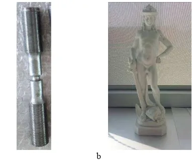
The first test object used was a steel laboratory specimen utilised for fatigue tests. The objects is 148.28 mm long, with the larger diameter of 20 mm and the smaller of 7.4 mm (fig. 1a). This object was chosen for three reasons: i) its shape is originated by the revolution of a profile described by an analytical function. This allows to calculate analytically, and relatively easily, the results of a fatigue test that can be used as theoretical reference; ii) the physical object can be used for laboratory test in different stress conditions measuring experimentally its physical reaction that can be used as experimental reference; iii) the 3D model of the object can be generated with 3D digitization, and the FEA can be applied to different instances of the 3D model originated by different 3D simplification approaches, allowing us to prove the effectiveness of the proposed method.
The second test object was a small copy in marble of the famous statue of David of Donatello, 290.5 mm high (fig. 1b). This object was chosen to create an accurate digital model by acquiring it with an active high-resolution and low uncertainty 3D device (see section 2.1 for the details), suitable to be used as an accurate shape reference from which derive the various simplified 3D models with different approaches. The model was useful to simulate the action of gravity forces on the most critical zones of
the shape in static condition. In addition, having a physical object similar to a work of art but with no practical artistic value, will allows to use it in the lab for possible physical tests. The future idea is to provide a laboratory test simulating an earthquake to compare the physical results with the FEA. This will be the only possibility to validate the proposed pipeline also in dynamic condition without potentially damaging Cultural Heritage artefacts of immense value.
a b
Figure 1. The two test objects: a) the lab specimen; b) the copy of the David of Donatello.
2. SURFACE ACQUISITION
2.1 3D data acquisition
The two test objects were surveyed with a structured light device Solutionix Rexcan CS whose technical features are summarized in table 1. The blue-light sensor for the pattern projection is suitable for digitizing small and medium not totally Lambertian objects and is considered the most precise type of sensor for 3D digitization in mechanical engineering.
Element Description
Camera resolution 2.0 Mega/ 5.0 Mega pixel Distance among points 0.035 ~ 0.2 mm
Lenses 12, 25 and 50 mm
Working distance 570 mm
Principle of scan Optical triangulation
Dimensions 400x110x210 mm
Weight 4 Kg
Light Blue LED
Unit mm
Table 1 Specification of the active 3D device used in the experiments
The 3D acquisition of the objects was carried out by placing the optical head on a base connected to a rotating plate (TA-300) composed of two axes, one for rotation around the vertical direction and one for the oscillation. The rotation allows a movement of ± 180 ° and the axis of oscillation allows to incline the plane where the specimen is located, up to 45° with respect of the vertical direction. With this scanning range, it is possible to limit to the minimum blind spots by reducing the scanning time up to 40%.
Given the size of the two test objects, it was decided to use the wide angle lenses (12mm) that have been calibrated using the appropriate calibration table fixed on the turntable. The range device can mount three different lenses, which specifications are summarized in Table 2.
The 3D device works with its own software for acquisition and alignment. For the two surveys, the Multiscan setting was used with an oscillation of ± 30° and ± 150° rotations for a total of 36 scans for each position of the object on the turntable (12 scans, one for each rotation for the 3 different oscillations, -30°, 0° and 30°).
Table 2 Specification of different lenses available
For the survey of the steel specimen, two groups of 36 scans were performed, while for the statue two groups of 72 scans. The survey of the little statue was more difficult due to its geometry and its dimensions. To have a complete model it was necessary to acquire the object twice for one position and then to turn it upside down and do other two session of scanning.
The Solutionix proprietary software automatically aligns the point clouds acquired in any position: for the lab specimen the final RMS error after the alignment of the two separate point clouds was 18 µm, while for the little statue 22 µm.
2.2 3D data processing and surface convertion
The two final, high-resolution models were cleaned and reoriented on a suitable reference system with the xy plane corresponding to the base of the model, and the z axis passing from the centre of gravity of the artefact. This was considered a proper and uniform positioning for the following finite element analysis.
After this step the two models were simplified with different strategies and converted from polygonal to NURBS in order to be processed by the volumetric mesher embedded in any FEA program.
The first simplification approach is based on the triangular simplification implemented in the Polyworks software package (IMCompress), based on a sequential optimization process that guides the removal of points from the triangulation leading to a gradual increase of its overall approximation error (Soucy and Laurendeau, 1995), and representing a derivation of the Delaunay Pyramid method first proposed in (De Floriani, 1989).
The second one involves the transformation of the original commercial software packages such as ZBrush by Pixologic. For the results presented in this paper ZBrush was used.
The geometrical complexity of the various models has been represented in terms of nodes of the mesh (or vertexes) rather than in terms of polygons, for the different way polygons are counted in case of triangular or quadrangular meshes. For quads the number of nodes and polygons is in fact approximately the same, while for triangular meshes the number of polygons is approximately the double of the nodes. This is quite obvious due to the fact that a squared element, once divided in two parts on one of its diagonals, produce two triangles. As a matter of facts the number of vertexes of a mesh is what defines the surface sampling and therefore in has been used as indicator for the level of detail of each mesh, independently of its triangular or quadrangular arrangement.
For each test object three simplification levels were estimated as suitable for the FEA package used in the experiments (ANSYS),
coming from two different mesh rearrangement strategies. As a result, for each test object six different simplified models were created, with different level of decimation.
The six models obtained were then imported in a CAD software (Rhino by McNeal) that performs the transformation from a mesh to a NURBS model, exported in a step file. Such file was finally used as input for the ANSYS volumetric mesher.
2.2.1 Laboratory specimen
The high-resolution model of the first test object counts 345026 polygons. Three different levels of decimation were applied, to have at the end three different model of approximately 12K, 6K and 3K vertexes (Fig. 2a-c).
Given the fact that the σ of the range device is equal to 0.015mm, it was decided to impose to the simplified mesh a level of simplification such as that the final mesh was 3σ respect to the uncertainty of the 3D sensor. Subsequently, two levels of simplification have been used to halve the number of polygons respectively, creating a situation of strong difference in the final number between the different models, maintaining however, a deviation between the simplified model and high-resolution mesh not exceeding 0.1mm. Table 3 shows the mean and the standard deviation in mm of the three simplified models for each simplification method, compared to the high-resolution one.
Retopologized quad model
Simplified triangular model
Mean Std dev Mean Std dev
12K vertexes 0.012 0.026 0.007 0.018
6K vertexes 0.044 0.037 0.010 0.026
3K vertexes 0.110 0.070 0.016 0.031
Table 3 Deviation of the three retopologized and simplified models of the lab specimen from the high-resolution one (mm).
The metric comparison reported in Table 3 shows that both the mean value and the standard deviation of the point distance between the vertexes of the reference model the mesh of each simplified model, are higher for the retopologized model than for the triangular mesh. The visual inspection of the different model version shown in Figure 2, gives instead an idea of the higher regularity of the retopologized mesh.
a b c
Figure 2. Visual comparison among the retopologized (left) and the decimated (right) models of the metallic specimen: a) 12K
vertexes; b) 6K vertexes; c) 3K vertexes.
2.2.2 Statue
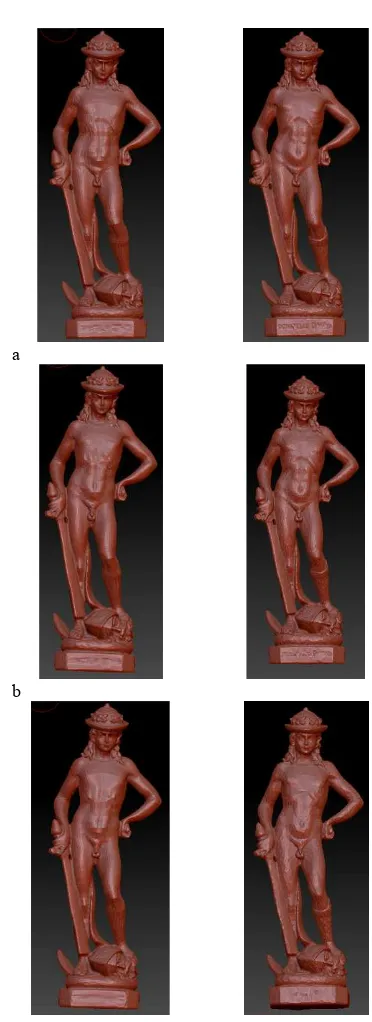
The final high-resolution model of the statue counts 2662378 polygons. Three models with different level of simplification were produced, starting from a model counting approximately 58K polygons, corresponding to a σ of 0.5mm, meaning a
standard deviation of 0.43mm. The other two models were produced following the same reasoning used for the specimen, imposing two level of simplification halving the number of vertexes and obtaining two models of approximately 29K and 14K vertexes respectively (Fig. 3a-c).
Retopologized model Triangular model
Mean Std dev Mean Std dev
58K vertexes 0.012 0.050 0.008 0.020
29K vertexes 0.020 0.100 0.017 0.036
14K vertexes 0.050 0.200 0.032 0.066
Table 4 Deviation of the three retopologized and decimated models of the statue from the high-resolution one (mm).
a
b
c
Figure 3. Visual comparison among the retopologized (left) and the decimated (right) models of the statue: a) 58K vertexes; b)
29K vertexes; c) 14K vertexes.
Table 4 summarizes the values of mean and standard deviation, expressed in mm, of the distance between the nodes of the reference mesh of the little David’s sculpture and the surface of the corresponding simplified meshes, obtained with the two different simplification methods and three different vertex densities (58k, 29k and 14k). For both quadrangular retopologized and triangular meshes the comparison shows that either the mean and the standard deviation are approximately halved for each doubling in the number of vertexes. Also in this case, as already seen for the model of the metallic lab specimen, the standard deviation of the retopologized model is more than double of the one associated with the triangular mesh.
3. FINITE ELEMENT ANALYSIS
After a first set of test executed with the FEA software Abaqus (Dassault Systems), a limitation in the maximum number of nodes of the model in our educational licence prevented us from obtaining all the results, therefore all the analyses were finally performed with the ANSYS structural analysis software (www.ansys.com).
3.1 Steel specimen
For the models of the steel specimen, a traction analysis was carried on. In order to have a correct value to compare the solutions achieved with the FEA, the analytical result of the traction for the steel specimen was calculated.
σ = Kt*σn (1)
where:
Kt = 1.66 is theoretical coefficient of carving, for traction σn is nominal stress
As known:
σn = N/A (2)
where:
A = area of the circle (diameter 7.4 mm)
N = 300N is the applied force
σ = Kt*σn = 1.66*7 = 11.62 MPa. (3)
The traction analysis was performed on each decimated and retopologized model imposing the following parameters:
- Young’s Modulus for steel 200000MPa - Poisson Ratio 0.3
- Traction on Z axis 300N;
- Displacement as boundary conditions on the other plane, components X=0, Y=0 and Z=0;
- Meshing element: Tetrahedrons; - Element size 1 mm;
- Size function adaptive;
- Fast transition in filling the volume.
Model ver. 12K 6K 3K Analytical
Retopology 11.31 11.60 11.86
11.62
Decimation 12.56 12.51 12.88
Table 5 Maximum value of the Von Mises stress resulting from the FEA on the different versions of the metallic specimen
model, compared to the analytical results.
2
A material is said to start to deform plastically when its von Mises stress reaches a critical value known as the yield strength σy. Prior to that stress
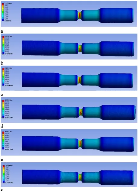
The results are shown in Figures 4 and summarized in Table 5, comparing them to the analytical result. The equivalent stress was evaluated considering the Von Mises yield criterion2 expressed in MPa.
a
b
c
d
e
f
Figure 4. Colour coded mapping of the Von Mises stress resulting from the FEA on the different 3D model versions: a)
retopologized 12k; b) simplified 12k; c) retopologized 6k; d) simplified 6k; e) retopologized 3k; f) simplified 3k;
The results make evident that, regarding the retopologized models, the maximum value of the Von Mises stress calculated with the FEA, deviates from the analytical one increasing while the number of vertexes of the models decreases, with very limited differences ranging from +0.20 to -0.31 kPa on a nominal value of 11.62 MPa (+1.7% to -2.7%). A similar increasing behaviour is exhibited by the simplified triangular mesh, with a significantly larger overestimation of the analytical value with errors ranging from +0.94 to 1.26 kPa (+8.1% to +10.8%).
Figure 5. Variation (%) of the max Von Mises stress for the two mesh structures and sizes.
level the material will deform elastically and will return to its original shape when the applied stress is removed.
3.2 Statue
The analysis was performed on each decimated and retopologized model imposing as load the Standard Earth Gravity, setting the following parameters:
- Density 2,6E-06 kg mm^-3
- Young’s Modulus for marble 78000 MPa - Poisson Ratio 0.3
- Gravity on -Y axis;
- Fixed Support under the basement of the statue as boundary condition, components X=0, Y=0 and Z=0; - Meshing element: Tetrahedrons;
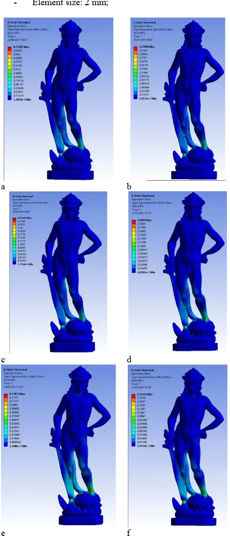
- Element size: 2 mm;
a b
c d
e f
Figure 6. Results with Gravity load on the different versions of the sculpture 3D model; a) 58K retopology; b) 58k decimation; c) 29k retopology; d) 29k decimation; e)14k retopology; f) 14k
decimation.
Model ver. 58K 29K 14K
Retopology 0.21 0.23 0.14
Decimation 0.23 0.21 0.16
Table 6 Maximum value of the Von Mises stress resulting from the FEA on different versions of the marble sculpture 3D
model.
The results are shown in Figures 6 and are summarized in Table 6. The equivalent stress was evaluated considering the Von Mises yield criterion expressed in MPa.
Starting from the assumption that there is not possibility to have a proper, calculated value to compare the FEA with, the results show that there is not a difference between the 58K and the 29K vertexes retopologized models, as happened for the comparison of these two models with the high-resolution one. Probably, dealing with a model of a very complicated object and starting from a resolution of more than 2.600.000 million vertexes, the level of reduction between 58K and 29K vertexes is not significant. The 14K vertexes model gave, instead, a result significantly lower than the other two models. The behaviour of the simulation starting from the simplified triangular mesh gave results extremely similar to those obtained by the retopologized mesh. The explanation seems to be the relationship between the size of the details and the simplification level, that in this particular case was not high enough for making evident the typical irregularities of a simplified triangular mesh, clearly visible instead on the steel test object.
4. CONCLUSIONS, OPEN ISSUES AND FUTURE
DEVELOPMENTS
The method proposed has exhibited interesting properties that indicates retopology as a reliable pre-processing step for using reality based 3D models as a basis for generating volumetric meshes suitable for FEA.
The first laboratory specimen allowed to demonstrate that the comparison between FEA results originated by a generically simplified triangular meshes and a meshes processed with the proposed method, involving quadrangular remeshing and simplification with retopology, give always results closer to the analytical reference. According to the results shown, the estimation error of the maximum Von Mises stress through the FEA, starting from the retopologized mesh, ranges from +1.7% for the less simplified mesh (12k vertexes) to -2.7% for the most simplified one (3k vertexes). Conversely, calculating the same parameter starting from a triangular simplified mesh, the percentage of error ranges from +8.1% for the less simplified mesh (12k vertexes) to +10.8% for the most approximate representation (3k vertexes), around 4 times more in terms error module in all cases.
The second test object, more complex in terms of shape, did not made evident any particular difference, probably because the relatively large number of points for describing the surface tended to make negligible possible variations of the FEA results, more “readable” close to an extreme level of simplification. In the future a few additional lever of simplification will be evaluated, for exploring more systematically this relationship. Regarding the first stage of the process the experiments made also evident that the transformation of a polygonal model in a set of NURBS surfaces, given the same number of vertices, works better (i.e. less NURBS patches are generated) if the model is retopologized rather than simply decimated in triangular elements. However, specially while testing the method on models of complex objects, it was clear that any minimal topological error in the mesh (either in quadrangular retopologized or simply triangular form) may become an overwhelming obstacle to the generation of the NURBS model. This involves the need of a very
accurate topological check, possible for example using the many features for this purpose available in the open source tool Meshlab (www.meshlab.net).
Although the proposed method allows to get a better starting point for the volumetric meshing stage preliminary to the actual finite element analysis, this latter step could be critical with both starting points in case of complex geometries. The different type of volumetric elements with which a model can be meshed in the FEA software and their size, determine in fact an additional degree of freedom involving a further sampling of the starting surface. Its sizing has to be carefully set-up depending on the smaller details size of the geometry described by the final NURBS model, independently of the simplification level applied at the beginning of the process. In addition, in order to obtain a more accurate result, the theory of FEA states that the best element is the hexahedron with a high number of nodes. This is related to the fact that the finite element analysis is performed using matrix, and higher is the number of nodes of the single element composing the models, higher is the accuracy of the results. To have the model meshed with such kind of element, the theory requires to segment the model in order to use the more accurate elements on the part of the model which is directly connected to the analysis.
Taking into account the model of the statue, it means to segment the model in order to mesh with hexahedron the part related to the feet and the lower part of the legs.
In this way that part can be also meshed with a higher level of density of the elements, meaning a higher accuracy, while the part that is not interested in the analysis can be meshed with a different element and a lower density.
The problem is that is not possible to segment these kind of models directly in the FEA software that are specifically created to deal with CAD model, geometrically simple and specifically organized. Using reality-based models impose to segment them before the import in the FEA software. The segmentation of a 3D model is yet an open issue, especially when it comes with automation.
A future stage of the research will be related to the study of object and structures made by layers of different materials instead of a single material (Iron or Marble in the examples), with variations of the internal elastic properties.
Finally, a specific study will be done with application of dynamic forces on the structure modelled with the proposed approach, in order to study the coherence of the simulated action with the real behaviour measured in the lab.
ACKOWLEDGMENTS
The authors wish to acknowledge the support of the European Union Joint Programming Initiative on Cultural Heritage (JPICH), for funding the research described in this paper, in the framework of the project Cultural Heritage Through Time (CHT2).
The authors would also like to thank Prof. Mario Guagliano from the department of Mechanical Engineering of Politecnico di Milano for his valuable suggestions in developing the work, and Dr. Ing. Francesco Furini from the same department, for his help and guidance in the use of the ANSYS software package.
REFERENCES
Bassier, M., Hadjidemetriou, G., Vergauwen, M., Van Roy, N., Verstrynge, E., 2016. Implementation of Scan-to-BIM and FEM for the Documentation and Analysis of Heritage Timber Roof Structures, in: Ioannides, M., Fink, E., Moropoulou, A., Hagedorn-Saupe, M., Fresa, A., Liestøl, G., Rajcic, V., Grussenmeyer, P. (Eds.), Digital Heritage. Progress in Cultural
Heritage: Documentation, Preservation, and Protection: 6th International Conference, EuroMed 2016, Nicosia, Cyprus, October 31 -- November 5, 2016, Proceedings, Part I. Springer International Publishing, Cham, pp. 79–90. doi:10.1007/978-3-319-48496-9_7
Brune, P., Perucchio, R., 2012. Roman Concrete Vaulting in the Great Hall of Trajan’s Markets: A Structural Evaluation. J. Archit. Eng. 18, 332–340. doi:10.1061/(ASCE)AE.1943-5568.0000086
Castellazzi, G., Altri, A.M.D., Bitelli, G., Selvaggi, I., Lambertini, A., 2015. From Laser Scanning to Finite Element Analysis of Complex Buildings by Using a Semi-Automatic Procedure. Sensors 15, 18360–18380. doi:10.3390/s150818360
De Floriani, L., 1989. A Pyramidal Data Structure for Triangle- Based Surface Description. IEEE Comput. Graph. Appl. 9, 67– 78. doi:10.1109/38.19053
Erkal, A., Ozhan, H.O., 2014. Value and vulnerability assessment of a historic tomb for conservation. Sci. World J. 2014, Article ID 357679. doi:10.1155/2014/357679 Society for Industrial and Applied Mathematics, Stuttgart, Germany. doi:10.1137/1.9780898717532
Jakob, W., Tarini, M., 2015. Instant Field-Aligned Meshes. Siggraph Asia 34, 15.
Oreni, D., Brumana, R., Della Torre, S., Banfi, F., Barazzetti, L., Previtali, M., 2014. Survey turned into HBIM: the restoration and the work involved concerning the Basilica di Collemaggio after the earthquake (L’Aquila). ISPRS Ann. Photogramm. Remote Sens. Spat. Inf. Sci. II-5, 267–273. doi:10.5194/isprsannals-II-5-267-2014
Riccardelli, C., Morris, M., Wheeler, G., Soultanian, J., Becker, L., Street, R., 2014. The Treatment of Tullio Lombardo’s Adam: A New Approach to the Conservation of Monumental Marble Sculpture. Metrop. Museum J. 49, 48–116. doi:10.1086/680027
Riveiro, B., Caamaño, J.C., Arias, P., Sanz, E., 2011. Photogrammetric 3D modelling and mechanical analysis of masonry arches: An approach based on a discontinuous model of voussoirs. Autom. Constr. 20, 380–388. doi:10.1016/j.autcon.2010.11.008
Shapiro, V., Tsukanov, I., 1999. Meshfree simulation of deforming domains. CAD Comput. Aided Des. 31, 459–471. doi:10.1016/S0010-4485(99)00043-3
Shapiro, V., Tsukanov, I., Grishin, A., 2011. Geometric Issues in Computer Aided Design/Computer Aided Engineering Integration. J. Comput. Inf. Sci. Eng. 11, 21005. doi:10.1115/1.3593416
Soucy, M., Laurendeau, D., 1995. A General Surface Approach to the Integration of a Set of Range Views. IEEE Trans. Pattern Anal. Mach. Intell. 17, 344–358. doi:10.1109/34.385982
Zvietcovich, F., Castaneda, B., Perucchio, R., 2014. 3D solid model updating of complex ancient monumental structures based on local geometrical meshes. Digit. Appl. Archaeol. Cult. Herit. 2, 12–27. doi:10.1016/j.daach.2015.02.001