F
I F T HE
D I T I O NFundamentals of Materials
Science and Engineering
An Interactive
e
•
Te x t
W illiam D. Callister, Jr.
Department of Metallurgical Engineering The University of UtahJohn W iley & Sons, Inc.
PC, the plastic that is used in many eyeglass lenses and safety helmets). R ed, blue, and yellow spheres represent carbon, hydrogen, and oxygen atoms, respectively.
Back Cover:D epiction of a monomer unit for polyethylene terephthalate (or PE T, the plastic used for beverage containers). R ed, blue, and yellow spheres represent carbon, hydrogen, and oxygen atoms, respectively.
Editor W ayne A nderson
Marketing Manager K atherine H epburn
A ssociate Production D irector L ucille B uonocore
Senior Production Editor M onique Calello
Cover and Text D esigner K arin G erdes K incheloe
Cover Illustration R oy W iem ann
Illustration Studio W ellington Studio
This book was set in 10/12 Times R oman by Bi-Comp, Inc., and printed and bound by Von H offmann Press. The cover was printed by Phoenix Color Corporation.
This book is printed on acid-free paper.
䊊
앝The paper in this book was manufactured by a mill whose forest management programs include sustained yield harvesting of its timberlands. Sustained yield harvesting principles ensure that the number of trees cut each year does not exceed the amount of new growth.
Copyright2001, John Wiley & Sons, Inc. A ll rights reserved.
No part of this publication may be reproduced, stored in a retrieval system or transmitted in any form or by any means, electronic, mechanical, photocopying, recording, scanning or otherwise, except as permitted under Sections 107 or 108 of the 1976 U nited States Copyright A ct, without either the prior written permission of the Publisher, or authorization through payment of
the appropriate per-copy fee to the Copyright Clearance Center, 222 R osewood D rive, D anvers, MA 01923, (508) 750-8400, fax (508) 750-4470. R equests to the Publisher for permission should be addressed to the Permissions D epartment, John Wiley & Sons, Inc., 605 Third A venue, New York, NY 10158-0012, (212) 850-6011, fax (212) 850-6008,
e-mail: PE R MR E Q @WILE Y.CO M.
To order books or for customer service call 1-800-CA LL-WILEY (225-5945).
ISBN 0-471-39551-X
DEDICATED TO THEMEMORY OF DAVID A. STEVENSON
Preface
F
undamentals of Materials Science and Engineeringis an alternate version of my text,Materials Science and Engineering: A n Introduction, Fifth Edition.The contents of both are the same, but the order of presentation differs and Fundamen-talsutilizes newer technologies to enhance teaching and learning.With regard to the order of presentation, there are two common approaches to teaching materials science and engineering—one that I call the ‘‘traditional’’ approach, the other which most refer to as the ‘‘integrated’’ approach. With the traditional approach, structures/characteristics/properties of metals are presented first, followed by an analogous discussion of ceramic materials and polymers. Intro-duction, Fifth Edition is organized in this manner, which is preferred by many materials science and engineering instructors. With the integrated approach, one particular structure, characteristic, or property for all three material types is pre-sented before moving on to the discussion of another structure /characteristic/prop-erty. This is the order of presentation inFundamentals.
Probably the most common criticism of college textbooks is that they are too long. With most popular texts, the number of pages often increases with each new edition. This leads instructors and students to complain that it is impossible to cover all the topics in the text in a single term. A fter struggling with this concern (trying to decide what to delete without limiting the value of the text), we decided to divide the text into two components. The first is a set of ‘‘core’’ topics—sections of the text that are most commonly covered in an introductory materials course, and second, ‘‘supplementary’’ topics—sections of the text covered less frequently. Fur-thermore, we chose to provide only the core topics in print, but the entire text (both core and supplementary topics) is available on the CD -R O M that is included with the print component ofFundamentals.D ecisions as to which topics to include in print and which to include only on the CD -R O M were based on the results of a recent survey of instructors and confirmed in developmental reviews. The result is a printed text of approximately 525 pages and an Interactive eT exton the CD -R O M, which consists of, in addition to the complete text, a wealth of additional resources including interactive software modules, as discussed below.
The text on the CD -R O M with all its various links is navigated using A dobe A crobat. These links within theInteractive eT extinclude the following: (1) from the Table of Contents to selected eT ext sections; (2) from the index to selected topics within the eT ext;(3) from reference to a figure, table, or equation in one section to the actual figure /table /equation in another section (all figures can be enlarged and printed); (4) from end-of-chapter Important Terms and Concepts to their definitions within the chapter; (5) from in-text boldfaced terms to their corresponding glossary definitions/explanations; (6) from in-text references to the corresponding appendices; (7) from some end-of-chapter problems to their answers; (8) from some answers to their solutions; (9) from software icons to the correspond-ing interactive modules; and (10) from the opencorrespond-ing splash screen to the supportcorrespond-ing web site.
The interactive software included on the CD -R O M and noted above is the same that accompaniesIntroduction, Fifth Edition. This software,Interactive M aterials Science and E ngineering, T hird E ditionconsists of interactive simulations and ani-mations that enhance the learning of key concepts in materials science and engi-neering, a materials selection database, and E -Z Solve: T he E ngineer’s E quation Solving and A nalysis T ool.Software components are executed when the user clicks on the icons in the margins of theInteractive eT ext;icons for these several compo-nents are as follows:
Crystallography and U nit Cells Tensile Tests
Ceramic Structures D iffusion and D esign Problem
Polymer Structures Solid Solution Strengthening
D islocations Phase D iagrams
E -Z Solve D atabase
My primary objective in Fundamentalsas in Introduction, Fifth Editionis to present the basic fundamentals of materials science and engineering on a level appropriate for university/college students who are well grounded in the fundamen-tals of calculus, chemistry, and physics. In order to achieve this goal, I have endeav-ored to use terminology that is familiar to the student who is encountering the discipline of materials science and engineering for the first time, and also to define and explain all unfamiliar terms.
The second objective is to present the subject matter in a logical order, from the simple to the more complex. E ach chapter builds on the content of previous ones. The third objective, or philosophy, that I strive to maintain throughout the text is that if a topic or concept is worth treating, then it is worth treating in sufficient detail and to the extent that students have the opportunity to fully understand it without having to consult other sources. In most cases, some practical relevance is provided. D iscussions are intended to be clear and concise and to begin at appro-priate levels of understanding.
The fourth objective is to include features in the book that will expedite the learning process. These learning aids include numerous illustrations and photo-graphs to help visualize what is being presented, learning objectives, ‘‘Why Study . . .’’ items that provide relevance to topic discussions, end-of-chapter ques-tions and problems, answers to selected problems, and some problem soluques-tions to help in self-assessment, a glossary, list of symbols, and references to facilitate understanding the subject matter.
The fifth objective, specific to Fundamentals, is to enhance the teaching and learning process using the newer technologies that are available to most instructors and students of engineering today.
Most of the problems inFundamentalsrequire computations leading to numeri-cal solutions; in some cases, the student is required to render a judgment on the basis of the solution. Furthermore, many of the concepts within the discipline of
materials science and engineering are descriptive in nature. Thus, questions have also been included that require written, descriptive answers; having to provide a written answer helps the student to better comprehend the associated concept. The questions are of two types: with one type, the student needs only to restate in his/ her own words an explanation provided in the text material; other questions require the student to reason through and /or synthesize before coming to a conclusion or solution.
The same engineering design instructional components found inIntroduction, Fifth Editionare incorporated in Fundamentals.Many of these are in Chapter 20, ‘‘Materials Selection and D esign Considerations,’’ that is on the CD -R O M. This chapter includes five different case studies (a cantilever beam, an automobile valve spring, the artificial hip, the thermal protection system for the Space Shuttle, and packaging for integrated circuits) relative to the materials employed and the ratio-nale behind their use. In addition, a number of design-type (i.e., open-ended) questions/problems are found at the end of this chapter.
O ther important materials selection /design features are A ppendix B, ‘‘Proper-ties of Selected E ngineering Materials,’’ and A ppendix C, ‘‘Costs and R elative Costs for Selected E ngineering Materials.’’ The former contains values of eleven properties (e.g., density, strength, electrical resistivity, etc.) for a set of approxi-mately one hundred materials. A ppendix C contains prices for this same set of materials. The materials selection database on the CD -R O M is comprised of these data.
S
UPPORTINGW
EBS
ITEThe web site that supports Fundamentals can be found at www.wiley.com / college/callister. It contains student and instructor’s resources which consist of a more extensive set of learning objectives for all chapters, an index of learning styles (an electronic questionnaire that accesses preferences on ways to learn), a glossary (identical to the one in the text), and links to other web resources. A lso included with the Instructor’s R esources are suggested classroom demonstrations and lab experiments. Visit the web site often for new resources that we will make available to help teachers teach and students learn materials science and engineering.
I
NSTRUCTORS’ R
ESOURCESTutorial and Mastery modes provide the student with hints integrated within each problem /question or a tailored study session that recognizes the student’s demon-strated learning needs. For more information, visit www.wiley.com /college/egrade.
A
CKNOW LEDGMENTSA ppreciation is expressed to those who have reviewed and /or made contribu-tions to this alternate version of my text. I am especially indebted to the following individuals: Carl Wood of U tah State U niversity, R ishikesh K. Bharadwaj of Systran Federal Corporation, Martin Searcy of the A gilent Technologies, John H . Weaver of The U niversity of Minnesota, John B. H udson of R ensselaer Polytechnic Institute, A lan Wolfenden of Texas A & M U niversity, and T. W. Coyle of the U niversity of Toronto.
I am also indebted to Wayne A nderson, Sponsoring E ditor, to Monique Calello, Senior Production E ditor, Justin Nisbet, E lectronic Publishing A nalyst at Wiley, and Lilian N. Brady, my proofreader, for their assistance and guidance in developing and producing this work. In addition, I thank Professor Saskia D uyvesteyn, D epart-ment of Metallurgical E ngineering, U niversity of U tah, for generating thee-G rade bank of questions/problems/solutions.
Since I undertook the task of writing my first text on this subject in the early 1980’s, instructors and students, too numerous to mention, have shared their input and contributions on how to make this work more effective as a teaching and learning tool. To all those who have helped, I express my sincere thanks!
Last, but certainly not least, the continual encouragement and support of my family and friends is deeply and sincerely appreciated.
WILLIA M D . CA LLISTE R, JR.
Salt L ak e City, Utah A ugust 2000
Contents
xi
Chapters 1 through 13 discuss core topics (found in both print and on the CD- ROM) and supplementary topics (in theeTextonly )
LIST OFSYMBOLS xix
1. Introduction 1
Learning O bjectives 2 1.1 H istorical Perspective 2
1.2 Materials Science and E ngineering 2
1.3 Why Study Materials Science and E ngineering? 4 1.4 Classification of Materials 5
1.5 A dvanced Materials 6
1.6 Modern Materials’ Needs 6
R eferences 7
2. Atomic Structure and Interatomic Bonding 9
Learning O bjectives 10
2.1 Introduction 10
ATOMICSTRUCTURE10
2.2 Fundamental Concepts 10
2.3 E lectrons in A toms 11
2.4 The Periodic Table 17
ATOMICBONDING INSOLIDS 18
2.5 Bonding Forces and E nergies 18
2.6 Primary Interatomic Bonds 20
2.7 Secondary Bonding or Van der Waals Bonding 24
2.8 Molecules 26
Sum m ary 27
Im portant T erm s and Concepts 27 R eferences 28
Q uestions and Problem s 28
3. Structures of Metals and Ceramics 30
Learning O bjectives 31
3.1 Introduction 31
CRYSTALSTRUCTURES 31
3.2 Fundamental Concepts 31
3.3 U nit Cells 32
xii ● Contents
3.5 D ensity Computations—Metals 37
3.6 Ceramic Crystal Structures 38
3.7 D ensity Computations—Ceramics 45
3.8 Silicate Ceramics 46
• The Silicates (CD -ROM) S-1
3.9 Carbon 47
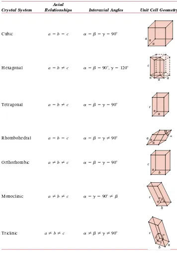
• Fullerenes (CD -ROM) S-3 3.10 Polymorphism and A llotropy 49 3.11 Crystal Systems 49
CRYSTALLOGRAPHICDIRECTIONS AND PLANES51
3.12 Crystallographic D irections 51 3.13 Crystallographic Planes 54
3.14 Linear and Planar A tomic D ensities (CD -ROM) S-4
•
3.15 Close-Packed Crystal Structures 58
CRYSTALLINE ANDNONCRYSTALLINE MATERIALS 62
3.16 Single Crystals 62
3.17 Polycrystalline Materials 62 3.18 A nisotropy 63
3.19 X-Ray D iffraction: D etermination of Crystal Structures (CD -ROM) S-6 •
3.20 Noncrystalline Solids 64
Sum m ary 66
Im portant T erm s and Concepts 67 R eferences 67
Q uestions and Problem s 68
4. Poly mer Structures 76
Learning O bjectives 77
4.1 Introduction 77
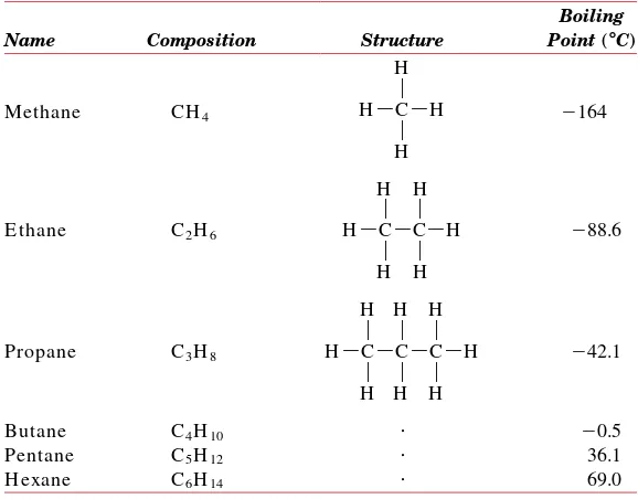
4.2 H ydrocarbon Molecules 77
4.3 Polymer Molecules 79
4.4 The Chemistry of Polymer Molecules 80
4.5 Molecular Weight 82
4.6 Molecular Shape 87
4.7 Molecular Structure 88
4.8 Molecular Configurations
(CD -ROM) S-11
•
4.9 Thermoplastic and Thermosetting
Polymers 90
4.10 Copolymers 91
4.11 Polymer Crystallinity 92 4.12 Polymer Crystals 95
Sum m ary 97
Im portant T erm s and Concepts 98 R eferences 98
Q uestions and Problem s 99
5. Imperfections in Solids 102
Learning O bjectives 103
5.1 Introduction 103
POINTDEFECTS 103
5.2 Point D efects in Metals 103 5.3 Point D efects in Ceramics 105 5.4 Impurities in Solids 107 5.5 Point D efects in Polymers 110 5.6 Specification of Composition 110
• Composition Conversions
(CD -ROM) S-14
MISCELLANEOUSIMPERFECTIONS 111
5.7 D islocations—Linear D efects 111 5.8 Interfacial D efects 115
5.9 Bulk or Volume D efects 118
5.10 A tomic Vibrations 118
MICROSCOPICEX AMINATION 118
5.11 G eneral 118
5.12 Microscopic Techniques
(CD -ROM) S-17
•
5.13 G rain Size D etermination 119
Sum m ary 120
Im portant T erm s and Concepts 121 R eferences 121
Q uestions and Problem s 122
6. Diffusion 126
Learning O bjectives 127
6.1 Introduction 127
6.2 D iffusion Mechanisms 127
6.3 Steady-State D iffusion 130 6.4 Nonsteady-State D iffusion 132 6.5 Factors That Influence D iffusion 136 6.6 O ther D iffusion Paths 141
6.7 D iffusion in Ionic and Polymeric Materials 141
Sum m ary 142
Im portant T erm s and Concepts 142 R eferences 142
Q uestions and Problem s 143
7. Mechanical Properties 147
Learning O bjectives 148
7.1 Introduction 148
7.2 Concepts of Stress and Strain 149
ELASTICDEFORMATION153
7.3 Stress–Strain Behavior 153 7.4 A nelasticity 157
MECHANICALBEHAVIOR— METALS 160
7.6 Tensile Properties 160 7.7 True Stress and Strain 167 7.8 E lastic R ecovery D uring Plastic
D eformation 170
7.9 Compressive, Shear, and Torsional
D eformation 170
MECHANICALBEHAVIOR— CERAMICS 171
7.10 Flexural Strength 171 7.11 E lastic Behavior 173
7.12 Influence of Porosity on the Mechanical Properties of Ceramics (CD -ROM) S-22 •
MECHANICALBEHAVIOR— POLYMERS 173
7.13 Stress–Strain Behavior 173 7.14 Macroscopic D eformation 175 7.15 Viscoelasticity (CD -ROM) S-22 •
HARDNESS ANDOTHERMECHANICALPROPERTY CONSIDERATIONS 176
7.16 H ardness 176
7.17 H ardness of Ceramic Materials 181 7.18 Tear Strength and H ardness of
Polymers 181
PROPERTYVARIABILITY ANDDESIGN/ SAFETY FACTORS 183
7.19 Variability of Material Properties 183 • Computation of A verage and Standard
D eviation Values (CD -ROM) S-28 7.20 D esign /Safety Factors 183
Sum m ary 185
Im portant T erm s and Concepts 186 R eferences 186
Q uestions and Problem s 187
8. Deformation and Strengthening Mechanisms 197
Learning O bjectives 198
8.1 Introduction 198
DEFORMATIONMECHANISMS FORMETALS 198
8.2 H istorical 198
8.3 Basic Concepts of D islocations 199 8.4 Characteristics of D islocations 201
8.5 Slip Systems 203
8.6 Slip in Single Crystals (CD -ROM) S-31 •
8.7 Plastic D eformation of Polycrystalline Metals 204
8.8 D eformation by Twinning
(CD -ROM) S-34
•
MECHANISMS OFSTRENGTHENING IN METALS 206
8.9 Strengthening by G rain Size R eduction 206
8.10 Solid-Solution Strengthening 208 8.11 Strain H ardening 210
RECOVERY, RECRYSTALLIZATION, ANDGRAIN GROW TH 213
8.12 R ecovery 213
8.13 R ecrystallization 213 8.14 G rain G rowth 218
DEFORMATIONMECHANISMS FORCERAMIC MATERIALS 219
8.15 Crystalline Ceramics 220 8.16 Noncrystalline Ceramics 220
MECHANISMS OFDEFORMATION AND FOR STRENGTHENING OFPOLYMERS 221
8.17 D eformation of Semicrystalline Polymers 221
8.18a Factors That Influence the Mechanical Properties of Semicrystalline Polymers [D etailed Version (CD -ROM)] S-35 •
8.18b Factors That Influence the Mechanical Properties of Semicrystalline Polymers (Concise Version) 223
8.19 D eformation of E lastomers 224
Sum m ary 227
Im portant T erm s and Concepts 228 R eferences 228
Q uestions and Problem s 228
9. Failure 234
Learning O bjectives 235
9.1 Introduction 235
FRACTURE 235
9.2 Fundamentals of Fracture 235
9.3 D uctile Fracture 236
• Fractographic Studies (CD -ROM) S-38 9.4 Brittle Fracture 238
9.5a Principles of Fracture Mechanics [D etailed Version (CD -ROM)] S-38 •
9.5b Principles of Fracture Mechanics (Concise Version) 238
9.6 Brittle Fracture of Ceramics 248 • Static Fatigue (CD -ROM) S-53
9.7 Fracture of Polymers 249
xiv ● Contents
FATIGUE 255
9.9 Cyclic Stresses 255
9.10 TheS –N Curve 257
9.11 Fatigue in Polymeric Materials 260 9.12a Crack Initiation and Propagation
[D etailed Version (CD -ROM)] S-54 •
9.12b Crack Initiation and Propagation (Concise Version) 260
9.13 Crack Propagation Rate
(CD -ROM) S-57
•
9.14 Factors That A ffect Fatigue Life 263 9.15 Environmental Effects (CD -ROM) S-62 •
CREEP265
9.16 G eneralized Creep Behavior 266 9.17a Stress and Temperature Effects
[D etailed Version (CD -ROM)] S-63 •
9.17b Stress and Temperature E ffects (Concise Version) 267
9.18 D ata Extrapolation Methods
(CD -ROM) S-65
•
9.19 A lloys for H igh-Temperature U se 268
9.20 Creep in Ceramic and Polymeric
Materials 269
Sum m ary 269
Im portant T erm s and Concepts 272 R eferences 272
Q uestions and Problem s 273
10 Phase Diagrams 281
Learning O bjectives 282
10.1 Introduction 282
DEFINITIONS ANDBASICCONCEPTS 282
10.2 Solubility Limit 283
10.3 Phases 283
10.4 Microstructure 284
10.5 Phase E quilibria 284
EQUILIBRIUMPHASEDIAGRAMS 285
10.6 Binary Isomorphous Systems 286
10.7 Interpretation of Phase D iagrams 288 10.8 D evelopment of Microstructure in
Isomorphous A lloys (CD -ROM) S-67 •
10.9 Mechanical Properties of Isomorphous A lloys 292
10.10 Binary E utectic Systems 292 10.11 D evelopment of Microstructure in
Eutectic A lloys (CD -ROM) S-70 •
10.12 E quilibrium D iagrams H aving
Intermediate Phases or Compounds 297 10.13 E utectoid and Peritectic R eactions 298 10.14 Congruent Phase Transformations 301
10.15 Ceramic Phase D iagrams (CD -ROM) S-77
•
10.16 Ternary Phase D iagrams 301
10.17 The Gibbs Phase Rule (CD -ROM) S-81 •
THEIRON– CARBONSYSTEM 302
10.18 The Iron – Iron Carbide (Fe – Fe3C)
Phase D iagram 302
10.19 D evelopment of Microstructures in Iron – Carbon A lloys 305
10.20 The Influence of Other A lloying Elements (CD -ROM) S-83 •
Sum m ary 313
Im portant T erm s and Concepts 314 R eferences 314
Q uestions and Problem s 315
11 Phase Transformations 323
Learning O bjectives 324
11.1 Introduction 324
PHASETRANSFORMATIONS INMETALS 324
11.2 Basic Concepts 325
11.3 The Kinetics of Solid-State R eactions 325
11.4 Multiphase Transformations 327
MICROSTRUCTURAL ANDPROPERTYCHANGES IN IRON– CARBONALLOYS327
11.5 Isothermal Transformation
D iagrams 328
11.6 Continuous Cooling Transformation D iagrams (CD -ROM) S-85
•
11.7 Mechanical Behavior of Iron – Carbon A lloys 339
11.8 Tempered Martensite 344
11.9 R eview of Phase Transformations for Iron – Carbon A lloys 346
PRECIPITATIONHARDENING 347
11.10 H eat Treatments 347
11.11 Mechanism of H ardening 349
11.12 Miscellaneous Considerations 351
CRYSTALLIZATION, MELTING,ANDGLASS TRANSITIONPHENOMENA INPOLYMERS 352
11.13 Crystallization 353
11.14 Melting 354
11.15 The G lass Transition 354 11.16 Melting and G lass Transition
Temperatures 354
11.17 Factors That Influence Melting and Glass Transition Temperatures
(CD -ROM) S-87
Sum m ary 356
Im portant T erm s and Concepts 357 R eferences 357
Q uestions and Problem s 358
12. Electrical Properties 365
Learning O bjectives 366
12.1 Introduction 366
ELECTRICALCONDUCTION 366
12.2 O hm’s Law 366
12.3 E lectrical Conductivity 367
12.4 E lectronic and Ionic Conduction 368 12.5 E nergy Band Structures in Solids 368
12.6 Conduction in Terms of Band and
A tomic Bonding Models 371 12.7 E lectron Mobility 372
12.8 E lectrical R esistivity of Metals 373 12.9 E lectrical Characteristics of Commercial
A lloys 376
SEMICONDUCTIVITY376
12.10 Intrinsic Semiconduction 377 12.11 E xtrinsic Semiconduction 379 12.12 The Temperature Variation of
Conductivity and Carrier Concentration 383
12.13 The Hall Effect (CD -ROM) S-91 •
12.14 Semiconductor D evices (CD -ROM) S-93 •
ELECTRICALCONDUCTION INIONICCERAMICS AND INPOLYMERS 389
12.15 Conduction in Ionic Materials 389 12.16 E lectrical Properties of Polymers 390
DIELECTRICBEHAVIOR 391
12.17 Capacitance (CD -ROM) S-99 •
12.18 Field Vectors and Polarization (CD -ROM) S-101
•
12.19 Types of Polarization (CD -ROM) S-105 •
12.20 Frequency D ependence of the D ielectric Constant (CD -ROM) S-106
•
12.21 D ielectric Strength (CD -ROM) S-107 •
12.22 D ielectric Materials (CD -ROM) S-107 •
OTHERELECTRICALCHARACTERISTICS OF MATERIALS 391
12.23 Ferroelectricity (CD -ROM) S-108 •
12.24 Piezoelectricity (CD -ROM) S-109 •
Sum m ary 391
Im portant T erm s and Concepts 393 R eferences 393
Q uestions and Problem s 394
13. Ty pes and Applications of Materials 401
Learning O bjectives 402
13.1 Introduction 402
TYPES OFMETALALLOYS 402
13.2 Ferrous A lloys 402
13.3 Nonferrous A lloys 414
TYPES OFCERAMICS 422
13.4 G lasses 423
13.5 G lass–Ceramics 423
13.6 Clay Products 424
13.7 R efractories 424
• Fireclay, Silica, Basic, and Special Refractories
(CD -ROM) S-110 13.8 A brasives 425
13.9 Cements 425
13.10 A dvanced Ceramics (CD -ROM) S-111 •
13.11 D iamond and G raphite 427
TYPES OFPOLYMERS 428
13.12 Plastics 428 13.13 E lastomers 431 13.14 Fibers 432
13.15 Miscellaneous A pplications 433 13.16 A dvanced Polymeric Materials
(CD -ROM) S-113 •
Sum m ary 434
Im portant T erm s and Concepts 435 R eferences 435
Q uestions and Problem s 436
Chapters 14 through 21 discuss just supplementary topics, and are found only on the CD- ROM (and not in print)
14. Sy nthesis, Fabrication, and Processing
of Materials(CD- ROM) S- 118
Learning O bjectives S-119
14.1 Introduction S-119
FABRICATION OFMETALS S- 119
14.2 Forming O perations S-119
14.3 Casting S-121
xvi ● Contents
THERMALPROCESSING OFMETALS S- 124
14.5 A nnealing Processes S-124 14.6 H eat Treatment of Steels S-126
FABRICATION OFCERAMICMATERIALS S- 136
14.7 Fabrication and Processing of G lasses S-137
14.8 Fabrication of Clay Products S-142
14.9 Powder Pressing S-145
14.10 Tape Casting S-149
SYNTHESIS ANDFABRICATION OFPOLYMERS S- 149
14.11 Polymerization S-150 14.12 Polymer A dditives S-151
14.13 Forming Techniques for Plastics S-153 14.14 Fabrication of E lastomers S-155 14.15 Fabrication of Fibers and Films S-155
Sum m ary S-156
Im portant T erm s and Concepts S-157 R eferences S-158
Q uestions and Problem s S-158
15. Composites (CD- ROM) S- 162
Learning O bjectives S-163
15.1 Introduction S-163
PARTICLE- REINFORCEDCOMPOSITES S- 165
15.2 Large-Particle Composites S-165 15.3 D ispersion-Strengthened Composites
S-169
FIBER- REINFORCEDCOMPOSITES S- 170
15.4 Influence of Fiber Length S-170 15.5 Influence of Fiber O rientation and
Concentration S-171
15.6 The Fiber Phase S-180
15.7 The Matrix Phase S-180
15.8 Polymer –Matrix Composites S-182
15.9 Metal–Matrix Composites S-185
15.10 Ceramic–Matrix Composites S-186
15.11 Carbon –Carbon Composites S-188
15.12 H ybrid Composites S-189 15.13 Processing of Fiber-R einforced
Composites S-189
STRUCTURALCOMPOSITES S- 195
15.14 Laminar Composites S-195
15.15 Sandwich Panels S-196
Sum m ary S-196
Im portant T erm s and Concepts S-198 R eferences S-198
Q uestions and Problem s S-199
16. Corrosion and Degradation of
Materials(CD- ROM) S- 204
Learning O bjectives S-205
16.1 Introduction S-205
CORROSION OFMETALS S- 205
16.2 E lectrochemical Considerations S-206
16.3 Corrosion R ates S-212
16.4 Prediction of Corrosion R ates S-214
16.5 Passivity S-221
16.6 E nvironmental E ffects S-222
16.7 Forms of Corrosion S-223
16.8 Corrosion E nvironments S-231
16.9 Corrosion Prevention S-232
16.10 O xidation S-234
CORROSION OFCERAMICMATERIALS S- 237 DEGRADATION OFPOLYMERS S- 237
16.11 Swelling and D issolution S-238
16.12 Bond R upture S-238
16.13 Weathering S-241
Sum m ary S-241
Im portant T erm s and Concepts S-242 R eferences S-242
Q uestions and Problem s S-243
17. Thermal Properties (CD- ROM) S- 247
Learning O bjectives S-248
17.1 Introduction S-248
17.2 H eat Capacity S-248
17.3 Thermal E xpansion S-250
17.4 Thermal Conductivity S-253
17.5 Thermal Stresses S-256
Sum m ary S-258
Im portant T erm s and Concepts S-259 R eferences S-259
Q uestions and Problem s S-259
18. Magnetic Properties (CD- ROM) S- 263
Learning O bjectives S-264
18.1 Introduction S-264
18.2 Basic Concepts S-264
18.3 D iamagnetism and Paramagnetism S-268
18.4 Ferromagnetism S-270
18.5 A ntiferromagnetism and
Ferrimagnetism S-272
18.6 The Influence of Temperature on
Magnetic Behavior S-276 18.7 D omains and H ysteresis S-276 18.8 Soft Magnetic Materials S-280
18.10 Magnetic Storage S-284 18.11 Superconductivity S-287
Sum m ary S-291
Im portant T erm s and Concepts S-292 R eferences S-292
Q uestions and Problem s S-292
19. Optical Properties (CD- ROM) S- 297
Learning O bjectives S-298
19.1 Introduction S-298
BASICCONCEPTSS- 298
19.2 E lectromagnetic R adiation S-298 19.3 Light Interactions with Solids S-300 19.4 A tomic and E lectronic Interactions
S-301
OPTICALPROPERTIES OFMETALS S- 302 OPTICALPROPERTIES OFNONMETALS S- 303
19.5 R efraction S-303
19.6 R eflection S-304
19.7 A bsorption S-305
19.8 Transmission S-308
19.9 Color S-309
19.10 O pacity and Translucency in Insulators S-310
APPLICATIONS OFOPTICALPHENOMENAS- 311
19.11 Luminescence S-311
19.12 Photoconductivity S-312
19.13 Lasers S-313
19.14 O ptical Fibers in Communications S-315
Sum m ary S-320
Im portant T erm s and Concepts S-321 R eferences S-321
Q uestions and Problem s S-322
20. Materials Selection and Design
Considerations (CD- ROM) S- 324
Learning O bjectives S-325
20.1 Introduction S-325
MATERIALSSELECTION FOR ATORSIONALLY STRESSEDCYLINDRICALSHAFT S- 325
20.2 Strength S-326
20.3 O ther Property Considerations and the Final D ecision S-331
AUTOMOBILEVALVESPRING S- 332
20.4 Introduction S-332
20.5 A utomobile Valve Spring S-334
ARTIFICIALTOTALHIPREPLACEMENT S- 339
20.6 A natomy of the H ip Joint S-339
20.7 Material R equirements S-341
20.8 Materials E mployed S-343
THERMALPROTECTIONSYSTEM ON THESPACE SHUTTLEORBITERS- 345
20.9 Introduction S-345
20.10 Thermal Protection System — D esign R equirements S-345
20.11 Thermal Protection
System — Components S-347
MATERIALS FORINTEGRATEDCIRCUIT PACKAGES S- 351
20.12 Introduction S-351
20.13 Leadframe D esign and Materials S-353
20.14 D ie Bonding S-354
20.15 Wire Bonding S-356
20.16 Package E ncapsulation S-358
20.17 Tape A utomated Bonding S-360
Sum m ary S-362 R eferences S-363
Q uestions and Problem s S-364
21. Economic, Environmental, and Societal Issues in Materials Science
and Engineering(CD- ROM) S- 368
Learning O bjectives S-369
21.1 Introduction S-369
ECONOMICCONSIDERATIONS S- 369
21.2 Component D esign S-370
21.3 Materials S-370
21.4 Manufacturing Techniques S-370
ENVIRONMENTAL ANDSOCIETAL CONSIDERATIONS S- 371
21.5 R ecycling Issues in Materials Science and E ngineering S-373
Sum m ary S-376 R eferences S-376
Appendix A The International Sy stem of Units (SI) 439
Appendix B Properties of Selected Engineering Materials 441
B.1 D ensity 441
B.2 Modulus of E lasticity 444 B.3 Poisson’s R atio 448 B.4 Strength and D uctility 449
B.5 Plane Strain Fracture Toughness 454 B.6 Linear Coefficient of Thermal
E xpansion 455
xviii ● Contents B.8 Specific H eat 462 B.9 E lectrical R esistivity 464 B.10 Metal A lloy Compositions 467
Appendix C Costs and Relative Costs for Selected Engineering Materials 469
Appendix D Mer Structures for Common Poly mers 475
Appendix E Glass Transition and Melting Temperatures for Common Poly meric Materials 479
Glossary 480
List of Symbols
T
he number of the section in which a symbol is introduced or explained is given in parentheses.xix A ⫽ area
A˚ ⫽ angstrom unit
Ai ⫽ atomic weight of element i(2.2)
A PF ⫽ atomic packing factor (3.4) %R A ⫽ ductility, in percent reduction in
area (7.6)
a ⫽ lattice parameter: unit cell x-axial length (3.4)
a ⫽ crack length of a surface crack (9.5a, 9.5b)
at% ⫽ atom percent (5.6)
B ⫽ magnetic flux density (induction) (18.2)
Br ⫽ magnetic remanence (18.7)
BCC ⫽ body-centered cubic crystal structure (3.4)
b ⫽ lattice parameter: unit cell y-axial length (3.11) b ⫽ Burgers vector (5.7) C ⫽ capacitance (12.17)
Ci ⫽ concentration (composition) of
component iin wt% (5.6) C⬘i ⫽ concentration (composition) of
component iin at% (5.6) Cv,Cp ⫽ heat capacity at constant
volume, pressure (17.2)
CPR ⫽ corrosion penetration rate (16.3)
CVN ⫽ Charpy V-notch (9.8)
%CW ⫽ percent cold work (8.11) c⫽ lattice parameter: unit cell
z-axial length (3.11) c⫽ velocity of electromagnetic
radiation in a vacuum (19.2) D ⫽ diffusion coefficient (6.3)
D ⫽ dielectric displacement (12.18) d ⫽ diameter
d ⫽ average grain diameter (8.9) dhk l⫽ interplanar spacing for planes of
Miller indicesh,k, and l(3.19) E ⫽ energy (2.5)
E ⫽ modulus of elasticity or Young’s modulus (7.3)
E ⫽ electric field intensity (12.3)
Ef ⫽ Fermi energy (12.5)
Eg⫽ band gap energy (12.6)
Er(t) ⫽ relaxation modulus (7.15)
%E L ⫽ ductility, in percent elongation (7.6)
e⫽ electric charge per electron (12.7)
e⫺⫽ electron (16.2)
erf ⫽ G aussian error function (6.4) exp ⫽ e, the base for natural
logarithms
F ⫽ force, interatomic or mechanical (2.5, 7.2)
F ⫽ Faraday constant (16.2)
FCC ⫽ face-centered cubic crystal structure (3.4)
G ⫽ shear modulus (7.3)
H ⫽ magnetic field strength (18.2) Hc⫽ magnetic coercivity (18.7)
H B ⫽ Brinell hardness (7.16)
H CP ⫽ hexagonal close-packed crystal structure (3.4)
H K ⫽ Knoop hardness (7.16) H R B, H R F ⫽ R ockwell hardness: B and F
nn ⫽ number-average degree of
polymerization (4.5) nw ⫽ weight-average degree of
polymerization (4.5)
P ⫽ dielectric polarization (12.18) P – B ratio ⫽ Pilling – Bedworth ratio (16.10)
p ⫽ number of holes per cubic meter (12.10)
Q ⫽ activation energy
Q ⫽ magnitude of charge stored (12.17)
R ⫽ atomic radius (3.4) R ⫽ gas constant
r⫽ interatomic distance (2.5) r⫽ reaction rate (11.3, 16.3)
rA,rC ⫽ anion and cation ionic radii (3.6) S ⫽ fatigue stress amplitude (9.10) SE M ⫽ scanning electron microscopy or
microscope T ⫽ temperature
Tc⫽ Curie temperature (18.6)
TC ⫽ superconducting critical
temperature (18.11)
Tg⫽ glass transition temperature
(11.15)
Tm ⫽ melting temperature
TE M ⫽ transmission electron microscopy or microscope T S ⫽ tensile strength (7.6)
t ⫽ time
tr⫽ rupture lifetime (9.16)
Ur⫽ modulus of resilience (7.6)
[uvw]⫽ indices for a crystallographic direction (3.12)
V ⫽ electrical potential difference (voltage) (12.2)
VC ⫽ unit cell volume (3.4)
VC ⫽ corrosion potential (16.4)
VH ⫽ H all voltage (12.13)
Vi⫽ volume fraction of phasei (10.7)
v⫽ velocity
vol% ⫽ volume percent
Wi⫽ mass fraction of phasei(10.7)
wt% ⫽ weight percent (5.6)
xx ● List of Symbols
H R 15N, H R 45W ⫽ superficial R ockwell hardness: 15N and 45W scales (7.16) H V ⫽ Vickers hardness (7.16)
h ⫽ Planck’s constant (19.2) (hk l) ⫽ Miller indices for a
crystallographic plane (3.13) I ⫽ electric current (12.2) I ⫽ intensity of electromagnetic
radiation (19.3) i ⫽ current density (16.3)
iC ⫽ corrosion current density (16.4)
J⫽ diffusion flux (6.3)
J⫽ electric current density (12.3) K ⫽ stress intensity factor (9.5a) Kc⫽ fracture toughness (9.5a, 9.5b)
KIc ⫽ plane strain fracture toughness
for mode I crack surface displacement (9.5a, 9.5b) k ⫽ Boltzmann’s constant (5.2) k ⫽ thermal conductivity (17.4)
l ⫽ length
lc⫽ critical fiber length (15.4)
ln ⫽ natural logarithm
log ⫽ logarithm taken to base 10 M ⫽ magnetization (18.2) Mn ⫽ polymer number-average
molecular weight (4.5) Mw ⫽ polymer weight-average
molecular weight (4.5)
mol% ⫽ mole percent
N ⫽ number of fatigue cycles (9.10) NA ⫽ A vogadro’s number (3.5)
Nf ⫽ fatigue life (9.10)
n ⫽ principal quantum number (2.3) n ⫽ number of atoms per unit cell
(3.5)
n ⫽ strain-hardening exponent (7.7) n ⫽ number of electrons in an
electrochemical reaction (16.2) n ⫽ number of conducting electrons
per cubic meter (12.7) n ⫽ index of refraction (19.5) n⬘ ⫽ for ceramics, the number of
x ⫽ length
x ⫽ space coordinate
Y ⫽ dimensionless parameter or function in fracture toughness expression (9.5a, 9.5b)
y ⫽ space coordinate z ⫽ space coordinate
움⫽ lattice parameter: unit celly –z interaxial angle (3.11)
움,웁,웂 ⫽ phase designations
움l⫽ linear coefficient of thermal
expansion (17.3)
웁⫽ lattice parameter: unit cellx –z interaxial angle (3.11)
웂 ⫽ lattice parameter: unit cellx –y interaxial angle (3.11)
웂 ⫽ shear strain (7.2)
⌬ ⫽ finite change in a parameter the symbol of which it precedes
⑀ ⫽ engineering strain (7.2)
⑀ ⫽ dielectric permittivity (12.17)
⑀r⫽ dielectric constant or relative permittivity (12.17)
⑀.s⫽ steady-state creep rate (9.16) ⑀T ⫽ true strain (7.7)
⫽ viscosity (8.16)
⫽ overvoltage (16.4)
⫽ Bragg diffraction angle (3.19)
D ⫽ D ebye temperature (17.2) ⫽ wavelength of electromagnetic
radiation (3.19)
애⫽ magnetic permeability (18.2)
애B ⫽ Bohr magneton (18.2)
애r⫽ relative magnetic permeability
(18.2)
애e⫽ electron mobility (12.7) 애h ⫽ hole mobility (12.10)
⫽ Poisson’s ratio (7.5)
⫽ frequency of electromagnetic radiation (19.2)
⫽ density (3.5)
⫽ electrical resistivity (12.2)
t⫽ radius of curvature at the tip of
a crack (9.5a, 9.5b)
⫽ engineering stress, tensile or compressive (7.2)
⫽ electrical conductivity (12.3)
* ⫽ longitudinal strength (composite) (15.5)
c⫽ critical stress for crack
propagation (9.5a, 9.5b)
fs ⫽ flexural strength (7.10)
m ⫽ maximum stress (9.5a, 9.5b)
matrix shear yield strength (15.4)
crss ⫽ critical resolved shear stress
(8.6)
m ⫽ magnetic susceptibility (18.2)
S
UBSCRIPTSc⫽ composite
cd ⫽ discontinuous fibrous composite cl⫽ longitudinal direction (aligned
fibrous composite)
C h a p t e r
1
/ Introduction
A
familiar item that is fabricated from three different material types is the beverage container. Beverages are marketed in aluminum (metal) cans (top), glass (ceramic)bot-tles (center), and plastic (polymer) botbot-tles (bottom). (Permission to use these
photo-graphs was granted by the Coca- Cola Company.)
After careful study of this chapter you should be able to do the following:
1. List six different property classifications of mate-rials that determine their applicability.
2. Cite the four components that are involved in the design, production, and utilization of materials, and briefly describe the interrelationships be-tween these components.
3. Cite three criteria that are important in the mate-rials selection process.
1.1 H
ISTORICALP
ERSPECTIVEMaterials are probably more deep-seated in our culture than most of us realize. Transportation, housing, clothing, communication, recreation, and food produc-tion —virtually every segment of our everyday lives is influenced to one degree or another by materials. H istorically, the development and advancement of societies have been intimately tied to the members’ ability to produce and manipulate materi-als to fill their needs. In fact, early civilizations have been designated by the level of their materials development (i.e., Stone A ge, Bronze A ge).
The earliest humans had access to only a very limited number of materials, those that occur naturally: stone, wood, clay, skins, and so on. With time they discovered techniques for producing materials that had properties superior to those of the natural ones; these new materials included pottery and various metals. Fur-thermore, it was discovered that the properties of a material could be altered by heat treatments and by the addition of other substances. A t this point, materials utilization was totally a selection process, that is, deciding from a given, rather limited set of materials the one that was best suited for an application by virtue of its characteristics. It was not until relatively recent times that scientists came to understand the relationships between the structural elements of materials and their properties. This knowledge, acquired in the past 60 years or so, has empowered them to fashion, to a large degree, the characteristics of materials. Thus, tens of thousands of different materials have evolved with rather specialized characteristics that meet the needs of our modern and complex society; these include metals, plastics, glasses, and fibers.
The development of many technologies that make our existence so comfortable has been intimately associated with the accessibility of suitable materials. A n ad-vancement in the understanding of a material type is often the forerunner to the stepwise progression of a technology. For example, automobiles would not have been possible without the availability of inexpensive steel or some other comparable substitute. In our contemporary era, sophisticated electronic devices rely on compo-nents that are made from what are called semiconducting materials.
1.2 M
ATERIALSS
CIENCE ANDE
NGINEERINGThe discipline ofm aterials scienceinvolves investigating the relationships that exist between the structures and properties of materials. In contrast,m aterials engineering is, on the basis of these structure –property correlations, designing or engineering the structure of a material to produce a predetermined set of properties. Throughout this text we draw attention to the relationships between material properties and structural elements.
2
4. (a) List the three primary classifications of solid materials, and then cite the distinctive chemi-cal feature of each.
1.2 Materials Science and Engineering ● 3
‘‘Structure’’ is at this point a nebulous term that deserves some explanation. In brief, the structure of a material usually relates to the arrangement of its internal components. Subatomic structure involves electrons within the individual atoms and interactions with their nuclei. O n an atomic level, structure encompasses the organization of atoms or molecules relative to one another. The next larger struc-tural realm, which contains large groups of atoms that are normally agglomerated together, is termed ‘‘microscopic,’’ meaning that which is subject to direct observa-tion using some type of microscope. Finally, structural elements that may be viewed with the naked eye are termed ‘‘macroscopic.’’
The notion of ‘‘property’’ deserves elaboration. While in service use, all materi-als are exposed to external stimuli that evoke some type of response. For example, a specimen subjected to forces will experience deformation; or a polished metal surface will reflect light. Property is a material trait in terms of the kind and magnitude of response to a specific imposed stimulus. G enerally, definitions of properties are made independent of material shape and size.
Virtually all important properties of solid materials may be grouped into six different categories: mechanical, electrical, thermal, magnetic, optical, and deterio-rative. For each there is a characteristic type of stimulus capable of provoking different responses. Mechanical properties relate deformation to an applied load or force; examples include elastic modulus and strength. For electrical properties, such as electrical conductivity and dielectric constant, the stimulus is an electric field. The thermal behavior of solids can be represented in terms of heat capacity and thermal conductivity. Magnetic properties demonstrate the response of a material to the application of a magnetic field. For optical properties, the stimulus is electromag-netic or light radiation; index of refraction and reflectivity are representative optical properties. Finally, deteriorative characteristics indicate the chemical reactivity of materials. The chapters that follow discuss properties that fall within each of these six classifications.
In addition to structure and properties, two other important components are involved in the science and engineering of materials, viz. ‘‘processing’’ and ‘‘perfor-mance.’’ With regard to the relationships of these four components, the structure of a material will depend on how it is processed. Furthermore, a material’s perfor-mance will be a function of its properties. Thus, the interrelationship between processing, structure, properties, and performance is linear, as depicted in the schematic illustration shown in Figure 1.1. Throughout this text we draw attention to the relationships among these four components in terms of the design, production, and utilization of materials.
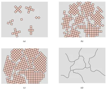
We now present an example of these processing-structure-properties-perfor-mance principles with Figure 1.2, a photograph showing three thin disk specimens placed over some printed matter. It is obvious that the optical properties (i.e., the light transmittance) of each of the three materials are different; the one on the left is transparent (i.e., virtually all of the reflected light passes through it), whereas the disks in the center and on the right are, respectively, translucent and opaque. A ll of these specimens are of the same material, aluminum oxide, but the leftmost one is what we call a single crystal—that is, it is highly perfect —which gives rise to its transparency. The center one is composed of numerous and very small single
Processing Structure Properties Performance
crystals that are all connected; the boundaries between these small crystals scatter a portion of the light reflected from the printed page, which makes this material optically translucent. A nd finally, the specimen on the right is composed not only of many small, interconnected crystals, but also of a large number of very small pores or void spaces. These pores also effectively scatter the reflected light and render this material opaque.
Thus, the structures of these three specimens are different in terms of crystal boundaries and pores, which affect the optical transmittance properties. Further-more, each material was produced using a different processing technique. A nd, of course, if optical transmittance is an important parameter relative to the ultimate in-service application, the performance of each material will be different.
1.3 W
HYS
TUDYM
ATERIALSS
CIENCE ANDE
NGINEERING?
Why do we study materials? Many an applied scientist or engineer, whether mechan-ical, civil, chemmechan-ical, or electrmechan-ical, will at one time or another be exposed to a design problem involving materials. E xamples might include a transmission gear, the superstructure for a building, an oil refinery component, or an integrated circuit chip. O f course, materials scientists and engineers are specialists who are totally involved in the investigation and design of materials.
Many times, a materials problem is one of selecting the right material from the many thousands that are available. There are several criteria on which the final decision is normally based. First of all, the in-service conditions must be character-ized, for these will dictate the properties required of the material. O n only rare occasions does a material possess the maximum or ideal combination of properties. Thus, it may be necessary to trade off one characteristic for another. The classic example involves strength and ductility; normally, a material having a high strength will have only a limited ductility. In such cases a reasonable compromise between two or more properties may be necessary.
A second selection consideration is any deterioration of material properties that may occur during service operation. For example, significant reductions in mechanical strength may result from exposure to elevated temperatures or corrosive environments.
Finally, probably the overriding consideration is that of economics: What will the finished product cost? A material may be found that has the ideal set of
FIGURE1.2
1.4 Classification of Materials ● 5
properties but is prohibitively expensive. H ere again, some compromise is inevitable. The cost of a finished piece also includes any expense incurred during fabrication to produce the desired shape.
The more familiar an engineer or scientist is with the various characteristics and structure –property relationships, as well as processing techniques of materials, the more proficient and confident he or she will be to make judicious materials choices based on these criteria.
1.4 C
LASSIFICATION OFM
ATERIALSSolid materials have been conveniently grouped into three basic classifications: metals, ceramics, and polymers. This scheme is based primarily on chemical makeup and atomic structure, and most materials fall into one distinct grouping or another, although there are some intermediates. In addition, there are three other groups of important engineering materials—composites, semiconductors, and biomaterials. Composites consist of combinations of two or more different materials, whereas semiconductors are utilized because of their unusual electrical characteristics; bio-materials are implanted into the human body. A brief explanation of the material types and representative characteristics is offered next.
METALS
Metallic materials are normally combinations of metallic elements. They have large numbers of nonlocalized electrons; that is, these electrons are not bound to particular atoms. Many properties of metals are directly attributable to these electrons. Metals are extremely good conductors of electricity and heat and are not transparent to visible light; a polished metal surface has a lustrous appearance. Furthermore, metals are quite strong, yet deformable, which accounts for their extensive use in structural applications.
CERAMICS
Ceramics are compounds between metallic and nonmetallic elements; they are most frequently oxides, nitrides, and carbides. The wide range of materials that falls within this classification includes ceramics that are composed of clay minerals, cement, and glass. These materials are typically insulative to the passage of electricity and heat, and are more resistant to high temperatures and harsh environments than metals and polymers. With regard to mechanical behavior, ceramics are hard but very brittle.
POLYMERS
Polymers include the familiar plastic and rubber materials. Many of them are organic compounds that are chemically based on carbon, hydrogen, and other nonmetallic elements; furthermore, they have very large molecular structures. These materials typically have low densities and may be extremely flexible.
COMPOSITES
SEMICONDUCTORS
Semiconductors have electrical properties that are intermediate between the electri-cal conductors and insulators. Furthermore, the electrielectri-cal characteristics of these materials are extremely sensitive to the presence of minute concentrations of impu-rity atoms, which concentrations may be controlled over very small spatial regions. The semiconductors have made possible the advent of integrated circuitry that has totally revolutionized the electronics and computer industries (not to mention our lives) over the past two decades.
BIOMATERIALS
Biomaterials are employed in components implanted into the human body for replacement of diseased or damaged body parts. These materials must not produce toxic substances and must be compatible with body tissues (i.e., must not cause adverse biological reactions). A ll of the above materials—metals, ceramics, poly-mers, composites, and semiconductors—may be used as biomaterials.兵For example, in Section 20.8 are discussed some of the biomaterials that are utilized in artificial hip replacements.其
1.5 A
DVANCEDM
ATERIALSMaterials that are utilized in high-technology (or high-tech) applications are some-times termedadvanced m aterials.By high technology we mean a device or product that operates or functions using relatively intricate and sophisticated principles; examples include electronic equipment (VCR s, CD players, etc.), computers, fiber-optic systems, spacecraft, aircraft, and military rocketry. These advanced materials are typically either traditional materials whose properties have been enhanced or newly developed, high-performance materials. Furthermore, they may be of all material types (e.g., metals, ceramics, polymers), and are normally relatively expen-sive. In subsequent chapters are discussed the properties and applications of a number of advanced materials—for example, materials that are used for lasers, integrated circuits, magnetic information storage, liquid crystal displays (LCD s), fiber optics, and the thermal protection system for the Space Shuttle O rbiter.
1.6 M
ODERNM
ATERIALS’ N
EEDSIn spite of the tremendous progress that has been made in the discipline of materials science and engineering within the past few years, there still remain technological challenges, including the development of even more sophisticated and specialized materials, as well as consideration of the environmental impact of materials produc-tion. Some comment is appropriate relative to these issues so as to round out this perspective.
Nuclear energy holds some promise, but the solutions to the many problems that remain will necessarily involve materials, from fuels to containment structures to facilities for the disposal of radioactive waste.
References ● 7
Furthermore, there is a recognized need to find new, economical sources of energy, and to use the present resources more efficiently. Materials will undoub-tedly play a significant role in these developments. For example, the direct con-version of solar into electrical energy has been demonstrated. Solar cells employ some rather complex and expensive materials. To ensure a viable technology, materials that are highly efficient in this conversion process yet less costly must be developed.
Furthermore, environmental quality depends on our ability to control air and water pollution. Pollution control techniques employ various materials. In addition, materials processing and refinement methods need to be improved so that they produce less environmental degradation, that is, less pollution and less despoilage of the landscape from the mining of raw materials. A lso, in some materials manufac-turing processes, toxic substances are produced, and the ecological impact of their disposal must be considered.
Many materials that we use are derived from resources that are nonrenewable, that is, not capable of being regenerated. These include polymers, for which the prime raw material is oil, and some metals. These nonrenewable resources are gradually becoming depleted, which necessitates: 1) the discovery of additional reserves, 2) the development of new materials having comparable properties with less adverse environmental impact, and /or 3) increased recycling efforts and the development of new recycling technologies. A s a consequence of the economics of not only production but also environmental impact and ecological factors, it is becoming increasingly important to consider the ‘‘cradle-to-grave’’ life cycle of materials relative to the overall manufacturing process.
兵The roles that materials scientists and engineers play relative to these, as well as other environmental and societal issues, are discussed in more detail in Chapter 21.其
R E F E R E N C E S
The O ctober 1986 issue ofScientific A m erican,Vol. 255, No. 4, is devoted entirely to various advanced materials and their uses. O ther references for Chapter 1 are textbooks that cover the basic funda-mentals of the field of materials science and engi-neering.
A shby, M. F. and D . R . H . Jones,E ngineering M ate-rials 1, A n Introduction to T heir Properties and A pplications,2nd edition, Pergamon Press, O x-ford, 1996.
A shby, M. F. and D . R . H . Jones,E ngineering M ate-rials 2, A n Introduction to M icrostructures, Pro-cessing and D esign, Pergamon Press, O xford, 1986.
A skeland, D . R ., T he Science and E ngineering of M aterials,3rd edition, Brooks/Cole Publishing Co., Pacific G rove, CA , 1994.
Barrett, C. R ., W. D . Nix, and A . S. Tetelman,T he Principles of E ngineering M aterials, Prentice H all, Inc., E nglewood Cliffs, NJ, 1973.
Flinn, R . A . and P. K. Trojan, E ngineering M a-terials and T heir A pplications,4th edition, John Wiley & Sons, New York, 1990.
Jacobs, J. A . and T. F. Kilduff,E ngineering M ateri-als T echnology,3rd edition, Prentice H all, U p-per Saddle R iver, NJ, 1996.
McMahon, C. J., Jr. and C. D . G raham, Jr., Intro-duction to E ngineering M aterials: T he B icycle and the W alk m an, Merion Books, Philadel-phia, 1992.
Murray, G . T.,Introduction to E ngineering M ateri-als— B ehavior, Properties, and Selection, Mar-cel D ekker, Inc., New York, 1993.
O hring, M., E ngineering M aterials Science, A ca-demic Press, San D iego, CA , 1995.
R alls, K. M., T. H . Courtney, and J. Wulff, Intro-duction to M aterials Science and E ngineering, John Wiley & Sons, New York, 1976.
D esign of E ngineering M aterials,2nd edition, WCB /McG raw-H ill, New York, 1999.
Shackelford, J. F.,Introduction to M aterials Science for E ngineers,5th edition, Prentice H all, Inc., U pper Saddle R iver, NJ, 2000.
Smith, W. F., Principles of M aterials Science and
E ngineering, 3rd edition, McG raw-H ill Book Company, New York, 1995.
C h a p t e r
2
/ Atomic Structure and
Interatomic Bonding
T
his micrograph, which represents the surface of agold specimen, was taken
with a sophisticated atomic
force microscope (AFM).
In-dividual atoms for this (111)
crystallographic surface
plane are resolved. Also
note the dimensional scale
(in the nanometer range)
be-low the micrograph. (Image
courtesy of Dr. Michael
Green, TopoMetrix
Corpo-ration.)
W hy Study
Atomic Structure and Interatomic Bonding?An important reason to have an understanding of interatomic bonding in solids is that, in some instances, the type of bond allows us to explain a material’s properties. For example, consider car-bon, which may exist as both graphite and diamond. W hereas graphite is relatively soft and
9
After careful study of this chapter you should be able to do the following:
1. Name the two atomic models cited, and note the differences between them.
2. Describe the important quantum- mechanical principle that relates to electron energies. 3. (a) Schematically plot attractive, repulsive, and
net energies versus interatomic separation for two atoms or ions.
(b) Note on this plot the equilibrium separation and the bonding energy.
4. (a) Briefly describe ionic, covalent, metallic, hy-drogen, and van der W aals bonds.
(b) Note what materials exhibit each of these bonding types.
2.1 I
NTRODUCTIONSome of the important properties of solid materials depend on geometrical atomic arrangements, and also the interactions that exist among constituent atoms or molecules. This chapter, by way of preparation for subsequent discussions, considers several fundamental and important concepts, namely: atomic structure, electron configurations in atoms and the periodic table, and the various types of primary and secondary interatomic bonds that hold together the atoms comprising a solid. These topics are reviewed briefly, under the assumption that some of the material is familiar to the reader.
A T O M I C S T R U C T U R E
2.2 F
UNDAMENTALC
ONCEPTSE ach atom consists of a very small nucleus composed of protons and neutrons, which is encircled by moving electrons. Both electrons and protons are electrically charged, the charge magnitude being 1.60⫻10⫺19 C, which is negative in sign for
electrons and positive for protons; neutrons are electrically neutral. Masses for these subatomic particles are infinitesimally small; protons and neutrons have ap-proximately the same mass, 1.67⫻10⫺27kg, which is significantly larger than that
of an electron, 9.11⫻ 10⫺31kg.
E ach chemical element is characterized by the number of protons in the nucleus, or theatomic number(Z).1For an electrically neutral or complete atom, the atomic
number also equals the number of electrons. This atomic number ranges in integral units from 1 for hydrogen to 92 for uranium, the highest of the naturally oc-curring elements.
The atom ic m ass (A) of a specific atom may be expressed as the sum of the masses of protons and neutrons within the nucleus. A lthough the number of protons is the same for all atoms of a given element, the number of neutrons (N) may be variable. Thus atoms of some elements have two or more different atomic masses, which are called isotopes. The atomic weight of an element corresponds to the weighted average of the atomic masses of the atom’s naturally occurring isotopes.2
The atomic mass unit (amu) may be used for computations of atomic weight. A scale has been established whereby 1 amu is defined as of the atomic mass of
10
1Terms appearing in boldface type are defined in the G lossary, which follows A ppendix E .
2The term ‘‘atomic mass’’ is really more accurate than ‘‘atomic weight’’ inasmuch as, in this
2.3 Electrons in Atoms ● 11
the most common isotope of carbon, carbon 12 (12C) (A ⫽ 12.00000). Within this
scheme, the masses of protons and neutrons are slightly greater than unity, and
A ⬵Z ⫹N (2.1)
The atomic weight of an element or the molecular weight of a compound may be specified on the basis of amu per atom (molecule) or mass per mole of material. In onemoleof a substance there are 6.023⫻1023(A vogadro’s number) atoms or
molecules. These two atomic weight schemes are related through the following equation:
1 amu /atom (or molecule) ⫽1 g/mol
For example, the atomic weight of iron is 55.85 amu /atom, or 55.85 g/mol. Sometimes use of amu per atom or molecule is convenient; on other occasions g (or kg) /mol is preferred; the latter is used in this book.
2.3 E
LECTRONS INA
TOMSATOMIC MODELS
D uring the latter part of the nineteenth century it was realized that many phenomena involving electrons in solids could not be explained in terms of classical mechanics. What followed was the establishment of a set of principles and laws that govern systems of atomic and subatomic entities that came to be known as quantum mechanics.A n understanding of the behavior of electrons in atoms and crystalline solids necessarily involves the discussion of quantum-mechanical concepts. H ow-ever, a detailed exploration of these principles is beyond the scope of this book, and only a very superficial and simplified treatment is given.
O ne early outgrowth of quantum mechanics was the simplified Bohr atomic model, in which electrons are assumed to revolve around the atomic nucleus in discrete orbitals, and the position of any particular electron is more or less well defined in terms of its orbital. This model of the atom is represented in Figure 2.1. A nother important quantum-mechanical principle stipulates that the energies of electrons are quantized; that is, electrons are permitted to have only specific values of energy. A n electron may change energy, but in doing so it must make a quantum jump either to an allowed higher energy (with absorption of energy) or to a lower energy (with emission of energy). O ften, it is convenient to think of these allowed electron energies as being associated with energy levels or states.
Orbital electron
Nucleus
These states do not vary continuously with energy; that is, adjacent states are separated by finite energies. For example, allowed states for the Bohr hydrogen atom are represented in Figure 2.2a. These energies are taken to be negative, whereas the zero reference is the unbound or free electron. O f course, the single electron associated with the hydrogen atom will fill only one of these states.
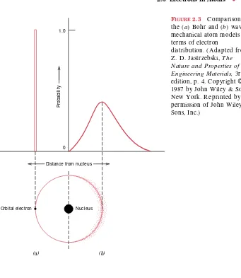
Thus, the Bohr model represents an early attempt to describe electrons in atoms, in terms of both position (electron orbitals) and energy (quantized energy levels). This Bohr model was eventually found to have some significant limitations because of its inability to explain several phenomena involving electrons. A resolu-tion was reached with a wave-mechanical model, in which the electron is considered to exhibit both wavelike and particle-like characteristics. With this model, an elec-tron is no longer treated as a particle moving in a discrete orbital; but rather, position is considered to be the probability of an electron’s being at various locations around the nucleus. In other words, position is described by a probability distribution or electron cloud. Figure 2.3 compares Bohr and wave-mechanical models for the hydrogen atom. Both these models are used throughout the course of this book; the choice depends on which model allows the more simple explanation.
QUANTUM NUMBERS