A study on Cold-formed Steel Frame
Connection: A review
Indra Komara
1, Endah Wahyuni
1, and Priyo Suprobo
1Abstract This paper is aimed to review the current researches on Cold-formed steel (CFS) structures, particularly for screw connections, welded connections, bolted connections and adhesive connections. Connection presents as a major parameter of the important elements for CFS framing system in order to attain its structural stability. The performance of different CFS connections is well-discussed in order to capture the behaviour of each type of connection. Based on the review assessment, the results highlighted that all types of connections except adhesive connections have shown the proper behaviour that can trigger the change of any design codes. Otherwise, adhesive connection is given several advantages that leads a novelty in the construction technology. Hence it still has some gaps of knowledge that are needed to be filled with comprehensive future researches.
Keywords cold-formed steel, connection, screw, welded, bolted, adhesive
AbstrakMakalah ini bertujuan untuk mengkaji ulang penelitian terkini mengenai struktur baja berbentuk dingin (CFS), terutama untuk sambungan sekrup, sambungan las, sambungan yang dilipat dan sambungan perekat. Sambungan merupakan parameter utama elemen penting sistem pembingkaian CFS untuk mencapai stabilitas strukturalnya. Kinerja koneksi CFS yang berbeda dibahas dengan baik untuk menangkap perilaku setiap jenis koneksi. Berdasarkan penilaian review, hasilnya menyoroti bahwa semua jenis koneksi kecuali koneksi perekat telah menunjukkan perilaku yang tepat yang dapat memicu perubahan kode desain apapun. Jika tidak, koneksi perekat diberi beberapa keunggulan yang mengarah pada kebaruan dalam teknologi konstruksi. Oleh karena itu masih ada beberapa celah pengetahuan yang perlu diisi dengan penelitian masa depan yang komprehensif.
Kata Kunci baja tahan dingin, sambungan, sekrup, dilas, dilipat, perekat
I.INTRODUCTION1
old-formed steel (CFS) frame is referred as lightweight steel frame building which is constructed using galvanized CFS sections. This type of construction is now called as industrialized building system (IBS) which becomes a famous construction choice in low to medium rise building and residential house construction. It provides various advantages as compared to traditional construction methods. For instance, simple and rapid construction, high quality controlled, ease of prefabrication and mass production, eliminates the need of formwork, cost and time saving, advance sustainable development by minimizing the waste of construction and recycling elements [1]. Moreover, CFS construction represents additional benefits that can be used to achieve an essential requirement for a competitive behaviour under seismic events [2].
Although CFS sections are becoming increasingly famous in construction field, there are a few problems associated with it, those are thin-walled section and connection failure. Thin-walled behaviour restricts the structural performance of CFS sections by premature buckling and instability. Over the past decade, the growing application of CFS as IBS had brought a large-wide researches to insure the improvement stability and reliability of the constructed of CFS structures. As the IBS demand increases gradually, many studies were done to estimate the safety issue of the use of CFS members as primary structural members, e.g. roof truss, frame, beam and column member [3]. Connection is implied as main support component which mechanically tightens the
1Indra Komara, Endah Wahyuni, and Priyo Suprobo are with
Departement of Civil Engineering, Institut Teknologi Sepuluh Nopember, Surabaya, 60111, Indonesia. Email: [email protected]; [email protected]; [email protected].
structural elements and focused at the location where the tightening action occurs [4]. It is imperative to transferring force and moment from a structural member to the supporting elements. Joint is modified as the connection plus the corresponding zone of interaction of each element. The characteristics of CFS joint are easy to install, ready in market, low cost installation and handling and less maintenance needed [5].
A. Section profiles of CFS
CFS steel shapes can amply be classified in two major groups. Those are indvidual structural frame members and panels and decks. Then, the common sections shapes such as I, L, C and Z are usually used in engineering pratices of CFS construction. Some shapes of CFS steel sections are illustrated on Figure 1. Nevertheless with the improvement of industrial cold forming procesess, the complex section of CFS types are possibly formed and enable to offer competitive solutions to attain structural weight reduction and having higher carrying capacity.
The application for these section type are modified by its functions, in instance, typical Z or C sections are used as a purlins and bracings in roof and system in resedential, commercial and industrial building and circular, square or rectangular hollow sections are used for structural members such as chords and webs in plane and space trussses. Then, the panels and decks, in most cases are used for roof decks, floor decks and wall panels.
Figure 1. Various shapes of CFS steel sections (Yu, 1990)
B. Advantages of CFS structure implementation
Some of the principle advantages of CFS sections are illustrated as follows [Adil dar, et al, 2014]:
CFS can be employed to produce almost any desired shape as per requirement.
Cross sectional shapes are formed o close tolerances and these can be consistently repeated for as long as required.
Pre-galvanised or pre-coated metals can be formed, so that high resistance to corrosion, besides an attractive surface finish, can be achieved.
High strength to weight ratio is well-achieved As the matter of fact, it is possible to distribute the material from the neutral axis in order to enchance the load carrying capacity, particularly in beam and trusses.
C. CFS design consideration
Several problems pertaining to CFS steel design is mainly caused by the thinner materials and cold-formed processes used in the production of CFS sections. Consequently, unlike the normally thicker steel members, the design of CFS members must be given consideration during the design phase of such members.The design considerations are listed such as buckling, torsion and distortion, stiffener in compression element, section properties, web crippling, ductility and plastic design, joint or connection, thickness limitations.
II.COLD-FORMED STEEL CONNECTION RESEARCHES
In recent years, review on the development of CFS structure has been increased significantly. The reviews concentrated on CFS section behaviour, for instance, compression member, distortional and element buckling, corrugated and curved panels, flexural members, torsion and distortion, web crippling, mechanical properties, composite and plasterboard construction, storage racks
and design optimization [6]. Finite element models are used to represent the actual case since the testing in full scale of connection can be very costly.
Due to the comparative low thickness of the material, connection technology plays an important role in the development of structure using CFS members. In fact, to know appropriate connection, the comparison of CFS connection should be evaluated. From [2-10], the review process was done mostly for CFS structural elements. More reviews are therefore made for CFS connections in the following discussion. The connections are classified as screw connections, welded connections, bolted connections and adhesive connections.
A. Screw Connection
Screw is a common type of connections which is used in CFS. In consequence of thinness of the CFS, screw connection provides advantages in simple design and fast handling. Screwed joints are suitable and effective when applying into the CFS section with the condition that total thickness should not give difficulty to the self-drilling process.
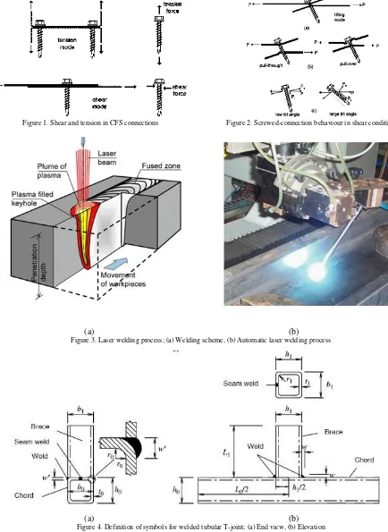
Figure 1. Shear and tension in CFS connections Figure 2. Screwed-connection behaviour in shear condition
(a) (b)
Figure 3. Laser welding process; (a) Welding scheme, (b) Automatic laser welding process
(a) (b)
Figure 4. Definition of symbols for welded tubular T-joint; (a) End view, (b) Elevation
Furthermore, the seismic design for screw joints were discussed [9][10]. In that matter, the X-braced shear walls with Net Section Failure (NSF) connection were needed to design in high seismic zone. The experimental data of screwed join in straps was illustrated. Then, elastic stiffness and tangent stiffness of the joint and the strap must be considered in design. Cold-formed roof sheeting connection with self-tapping screw was also investigated at ambient and elevated temperature [10]. Another analysis, the effect of edge and end distance on the connection resistance was conducted by using finite element method and experimental investigation. At
ambient temperature, 2.5 of reduction factor could be used for shear-out failure. The equations for the ratio of the edge distance to the diameter is in the range of 1.00-1.75. The observed failures included bearing, failure and material failure. It was found that current design specifications are conservative towards strength prediction at elevated temperatures. For transient state test, failure mode of the screwed connection may change as the load increases.
studied with different configurations and compared by using Eurocode analytical model. As the result, initial stiffness of the joints increased as the beam depth increased. The examined screwed joints were all considered as partial strength category when classified by their strength, as the strength of joint was more than 25% of connected beam flexural resistance.
B. Welded Connection
Welded joints offer rigid joints between CFS members. In this case, welding operation requires skilled workers. It is also served with extra care as compared to other joints. The review is specialized to laser beam welding (LBW). The LBW process is illustrated in Figure 3. [12].
LBW is widely used in automotive industry, yet it is still considered as new term in CFS construction. In this study, experiment tests were consisting of element test i.e lap-shear and U-tension tests and beam flexural tests. The analysing was intended at examining the innovative connection in building up CFS beams. The LBW concept is precisely welded to the joints that will minimize the error and thus intensify the safety of the connections.
Additionally, for connection configuration on the flanges, welds with spacing of 100 mm have the same flexural resistance with spacing of 50 mm. The characterization of failure of laser welds was conducted under combined loading condition [12]. The failures were classified into two regions, namely, base metal failure and interfacial failure.
TABLE 1.
THE TENSILE STRENGTH OF ADHESIVE JOINT No Wide Thickness Overlap
THE COMPARISON JOINT STRENGTH OF ADHESIVE JOINT AND SELF-SCREWED DRILLING JOINT
Self-screwed drilling joint Adhesive joint
Number of screw Ultimate stress
(Kgf/cm2) Type of adhesive
Another analysis was conducted on tubular X-joint using the carbon steel replaced by stainless steel [13]. Subsequent to stainless steel does not have a distinct yield stress, 0.1%, 0.2%, 0.5% and 1.0% of proof stresses were put in the investigation. In that condition, three failure modes happened as follows: chord face failure, chord side wall failure and local buckling failure of brace. The study expressed that the 0.2% of proof stress is reasonable in predicting the design strength of stainless steel tubular X-joint in rectangular hollow section for two condition i.e. ultimate limit state and serviceability limit state.
The analysis on stainless steel tubular T-joint, square and rectangular hollow section brace and chord members was hold which is presented in Figure 4. The study is coincident to the recommendation by [13] that the 0.2% of proof stress is reasonable in predicting the design strength of stainless steel tubular T-joint in rectangular hollow section, in both condition as X-joint.
On the contrary, T-joint in Square Hollow Section (SHS) or Rectangular Hollow Section (RHS) and Circular Hollow Section (CHS) have been analysed. In that experiment analysis, a web buckling formula was proposed to foresee the deformation limit and ultimate strength in RHS [14]. In foreseeing the web buckling strength and chord flange strength, the corner radius of
RHS was considered. Other studies were conducted that the fatigue test and design in tube-to-tube joints and section-to-section plate connections of SHS under in plane bending [15]. Further, CHS T-joint is given a preferable joint especially on the fatigue strength which is compared to SHS T-joint. The SHS T-joint behaviour is also investigated using finite element analysis [16]. A model was expanded to study the sensitivity of parameters. The plastic behaviour of knee joint of RHS was conducted as well. Subsequently, it was found that the internal sleeve connection was fitted in plastic design.
C. Bolted Connection
Bolted connection is an ordinary fastener in steel construction which can be applied to both steel section (hot-rolled) and CFS section. In this review, for bolted connection, the research is focused on two types of connection i.e. stainless steel and lapped Z-purlins.
The previous research proposed equations of design for cold-formed carbon steel bolted connections. The net section was applicable to light steel framing design as illustrated in Figure 5. Experimental analysis for bolted connection between thin gauge stainless steel was performed [17].
predicting tear-out failure and net section rupture but overestimate the bearing resistance of bolted connection. NSF and bearing capacity were examined in stainless CFS bolted connections. The edge distance namely e2 and bolt
configuration were the main parameters that affect the net section rupture of bolted connection [18]. From that research, a recommend design equation for net section capacity of stainless steel connection was verified by statistical and numerical analysis [17]. In fact, there are two equations of bearing design for two conditions. The first condition is checked by fracture, whereas the second condition looks the deformation under the service loads [18].
Figure 5. Net section failure - Comparison between deformed test specimen and numerical model.
Subsequently, a finite element model consists of bolted connection in thin-walled stainless steel plates under static shear was occurred [19]. In this parameter, referred to the Japanese Steel Design Standards (AIJ), its design has less accuracy in predicting the ultimate behaviour specifically, failure mode, ultimate strength and the occurrence of curling of stainless steel bolted connection loaded in static shear. With the result, the study proposed a modified formula for calculating the ultimate strength. The load-displacement curves of bolted connection are estimated with nonlinear material and no geometric finite element analysis. The finite element analysis was used to clarify the structural behaviour of single shear bolted connections with two bolts in CFS structures [19]. As the matter of fact, the ultimate strength, failure mode and curling of the finite element model give a proper agreement in comparison to experimental data.
Figure 6. Finite element model and analysis result; (a) Finite element condition, (b) Deformed shape (curling)
Furthermore, the behaviour of bolted connection in multi-span of purlin was conducted [20]. Here, rigid connection was assumed in old practice for the ease calculation but in the laboratory test, the research was conducted in semi rigid in bolted lapped connection. The result shown a different failure when semi rigid connection was taken. Later on, the web crippling at the edge of the lapped zone was given to calculate with bending moment in multi-span cold-formed Z-purlins using bolted lapped connection. In [21], the lap edge single section was considered as critical in purlin design and lateral torsional buckling when in the case of laterally unrestrained purlins. Several conclusions were illustrated from the research where bending moment was dominating the load-carrying resistance, the critical section was the edge of lapped connection, moment resistance of the edge section of lapped connection was twice less than the moment resistance at internal support section, the effective flexural rigidity was affected by the length of lapped connections, and the effective flexural rigidity of lapped connection could be estimated by using stress analysis and deflection analysis.
D.Adhesive Connection
Adhesive connection offers sturdy connection that can significantly affect the structure resistance. In most cases of CFS structures, connection provides as a weakness parameter that reduce the load bearing capacity. That condition often leads to a structure premature collapse. Consequently, in this paper, adhesive connection is given as an alternative solution to response that condition. Adhesive joints for CFS connections potentially offer an increase in the incremental strength of the structure [21]. The research scope of adhesive connection is concerned in two conditions; the capacity and the variety of connections, specifically for 0.75 mm substrate thickness.
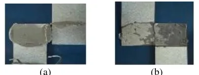
Experimental tests were employed by using epoxy resin and polyester resin on adhesively bonded Single Lap Joints (SLJ) and Flexural Joints (FJ) which is subjected to static loading [9]. A screw joint using 6 mm drilling screw was added to the SLJ specimen as illustrated in Figure 2 and another parameter is also added to the FJ specimen in Figure 3. Furthermore, the ultimate strength and strain due to axial and flexural loading of the joints were measured as well as visual investigation by using video microscope.
Figure 7. Failure mode of screw connections on the CFS structure
(a) (b)
The following study was conducted to the behaviour of adhesive connection compared to self-drilling connection [22]. Tensile strength of self-drilling screw joint and adhesive joint on CFS structure were evaluated by using Sikadur 31 CF Normal and JB Weld. The result is presented in the Table 2.
III.DISCUSSION
A set of various research of CFS connection was evaluated recently. On cold-formed screwed connection, some research studies are focused on CFS sheeting due to drilling difficulty for primary structural members. Certain screw configurations were investigated to obtain optimum resistance strength. In this condition, economical design is always given as a major issue and to have the economical design, the current research should be adopted. The research studies are furthered to structural behaviour at elevated temperature.
Screw connection is a convenient method for joining thin steel section or steel sheeting. It does not require heavy and precise tools at site and speed up the prefabrication process. However, the difficulty of self-drilling process will increase with the increment of steel thickness and steel grade. For secondary structural member, screwed connection has shown the effectiveness in structural member. Otherwise, for primary member, the increased section in steel grade a section thickness for better resistance has induced the problem of drilling.
For welded connection, especially LBW, the focus of current research is majority to find out the strength of the joint on various sections and various connections, the reliability of LBW applied in structures, the influence of LBW types in strength in joints, the influence of heat affected zone, failure mode that may occur and so forth. LBW which is popular on the building industry, also should be carried out non-only on build-up section joints but also beam-to-beam joints, beam-to-column joints, column-to-column joints and column-to-base joints. Other than that, the heat from welding process will reduce the strength of CFS section. According to AISI [2], the minimum section thickness is roughly in the range of 1.3 mm to 1.7 mm.
For bolted connection, the research is concentrated on the secondary members such as purlin and truss design. Minor references are found for primary loads leading members, beam-to-column connection, beam-to-beam connection and column base connection. Bolted connection in CFS structure is proposed semi rigid behaviour according to stiffness classification. The bolted connection in most cases is preferential for mass construction sector. It is caused, the reduction of skilled worker at construction site using bolted connection application is able to reduce the cost of constriction as compared to screw and welded construction.
The last, for adhesive connections, in most of the current practice, adhesive connection is only used for special aerospace joints. It has exiguous research about the application of adhesive connection on the CFS structure. Due to thin-walled behaviour, CFS denotes various failure mode and large deformation. Its connection imperfection also becomes one of the failure parameter. So that the contribution of applied component from the developed joints should be identified to achieve more reliable CFS structural behaviour. The paper shows
that the adhesive joint gives a strength improvement is about 27.81% till 81.84% using SLJ with sikadur 31 CF normal and JB weld, respectively [10]. In that case, there are still many parameter studies that should be analysed. Thus, comprehensive studies on adhesive behaviour should be carried out to improve the reliability of joint design.
IV.CONCLUSION
This paper summarizes several previous studies on CFS connection in the area of screw connection, welded connection, bolted connection and adhesive connection. The review is initiated by some scopes of discussion as the length of the publication. Screw is a prepared regular connection that is used in cold-formed steel due to the thinness of the cold-formed steel sections. Welded connection is considered as a rigid joint which can improve the structural connection. In fact, it needs a required skilled-workers. Bolted connection is a common design for steel connection. However, for CFS connection, it requires extra consideration due to a thin section and design standard. The last is adhesive connection, it offers a strong joint which can allocate a sturdy connection. Adhesive connection will influence the long-term performance. But, there are some gaps of knowledge that are needed to be filled up on the design codes for adhesive connection. This could be completed with comprehensive future research. From the studies, there are several other researches that are worth to be further discussed, particularly on the behaviour of frame truss adhesive connection.
IV.ACKNOWLEDGMENT
The research study described in this paper was supported by a Grant from LPDP (Indonesia Endowment Fund for Education of Ministry of Finance) under the research funding program for basic laboratory research.
REFERENCES
[1] Y. H Lee, “Review on Cold-Formed Steel Connections,” Sci. world J., 2014.
[2] AISI, “AISI cold-formed steel framing seismic design optimization
project,” 2010.
[3] A. Bayan, S. Sariffuddin, and H. O, “Cold-formed steel joint and structure –a review,” Cold-formed steel Jt. Struct. – a Rev., vol. 2, no. 2, pp. 621–634, 2011.
[4] J. B. P. L. A.M. Wrzesien, “Cold-formed steel portal frame joints; a
review,” in ineteenth International Specialty Conference on Cold-Formed Steel Structures St. Louis, 2008, pp. 591–605.
[5] B. Y. E.Ellobody, “Behaviour of Cold-formed steel plain angle
columns,” J. Struct. Eng., vol. 131, pp. 457–466, 2005.
[6] J. Mills and R., “Self-drilling screw joints for coldformed channel
portal frames,” J. Struct. Eng., vol. 130, no. 11, pp. 1799–1806, 2004.
[7] J. H. Song and H. Huh, “Failure characterization of spot welds under
combined axialshear loading conditions,” Int. J. Mech. Sci., vol. 53, no. 7, pp. 513–525, 2011.
[8] T. Peköz, “Design of cold-formed steel screw connections,” in Proc., 10th Int. Specialty Conf. on Cold-Formed Steel Structures, 1990.
[9] and A. R.-F. M. Casafont, A. Arnedo, F. Roure, Experimental testing of joints for seismic design of lightweight structures—part 1: screwed joints in straps. Thin-Walled Structures, 2006.
[10] S. Yan and B. Young, “Screwed connections of thin sheet steels at elevated temperatures—part I: steady state tests,” Eng. Struct., vol. 35, pp. 234–243, 2012.
958, 2009.
[12] G. D. L. and M. R. G. R. Landolfo, O. Mammana, F.Portioli,
“Experimental investigation on laser welded connections for built -up cold-formed steel beams,” J. Constr. steel Res., vol. 65, pp. 192– 208, 2009.
[13] B. Y. R. Feng, “Experimental investigation of cold-formed stainless steel tubular T-joints,” Thin-Walled Struct., vol. 46, pp. 1129–1142, 2008.
[14] X. L. Zhao, “Deformation limit and ultimate strength of welded T -joints in cold-formed RHS sections,” J. Constr. Steel Res., vol. 53, no. 2, pp. 149–165, 2000.
[15] G. X. L. Tong, D. Yan, and X. L. Zhao, “Fatigue test and design of diamond bird-break SHS T-joints under axial loading in brace,” J. Constr. steel Res., vol. 118, pp. 49–59.
[16] R. Moazed, W. Szyszkowski, and R. Fotouhi, “The in-plane behaviour and FE modeling of a T-joint connection of thinwalled
square tubes,” Thin-Walled Struct., vol. 47, no. 6–7, pp. 816–825, 2009.
[17] E. L. Salih, L. Gardner, and D. A. Nethercot, “Numerical investigation of net section failure in stainless steel bolted
connections,” J. Constr. Steel Res., vol. 66, no. 12, pp. 1455–1466, 2010.
[18] E. L. Salih, L. Gardner, and D. A. Nethercot, “Bearing failure in
stainless steel bolted connections,” Eng. Struct., vol. 33, pp. 549– 562, 2011.
[19] T. S. Kim, H. Kuwamura, and T. J. Cho, “A parametric study on
ultimate strength of single shear bolted connections with curling,”
Thin-walled Struct., vol. 46, pp. 866–871, 1007.
[20] D. Dubina and V. Ungureanu, “Behaviour of multi-span cold-formed Z-purlins with bolted lapped connections,” 2010.
[21] S. N. R. Anwar, E. Wahyuni, and P. Suprobo, “Tensile performance of adhesive joint on the cold-fromed steel structure,” Int. J. Eng. trends Technol., vol. 10, pp. 231–234, 2014.
[22] S.N.R. Anwar, P. Suprobo, and E. Wahyuni, “Axial and Flexural Performance of Adhesive Connection on Cold-Formed Steel
Structures,” Int. J. Technol., vol. 4, pp. 699–708, 2015.
[23]R. Landolfo, O. Mammana, F. Portioli, G. Di Lorenzo, and M.R.
Guerrieri. 2008. “Laser welded built-up cold-formed steel beams: