Published in IET Signal Processing Received on 9th January 2013 Revised on 26th April 2013 Accepted on 9th May 2013 doi: 10.1049/iet-spr.2013.0015
ISSN 1751-9675
Analysis by synthesis spatial audio coding
Ikhwana El
fi
tri
1,2, Xiyu Shi
1,3, Ahmet Kondoz
1,31
I-Lab Multimedia Communications Research, University of Surrey, Guildford, GU2 7XH, UK
2
Electrical Engineering Department, Faculty of Engineering, Andalas University, Kampus Unand Limau Manih, Padang, Indonesia
3
Mulsys Limited, Guildford, UK E-mail: i.elfi[email protected]
Abstract:This study presents a novel spatial audio coding (SAC) technique, called analysis by synthesis SAC (AbS-SAC), with a capability of minimising signal distortion introduced during the encoding processes. The reverse one-to-two (R-OTT), a module applied in the MPEG Surround to down-mix two channels as a single channel, isfirst configured as a closed-loop system. This closed-loop module offers a capability to reduce the quantisation errors of the spatial parameters, leading to an improved quality of the synthesised audio signals. Moreover, a sub-optimal AbS optimisation, based on the closed-loop R-OTT module, is proposed. This algorithm addresses a problem of practicality in implementing an optimal AbS optimisation while it is still capable of improving further the quality of the reconstructed audio signals. In terms of algorithm complexity, the proposed sub-optimal algorithm provides scalability. The results of objective and subjective tests are presented. It is shown that significant improvement of the objective performance, when compared to the conventional open-loop approach, is achieved. On the other hand, subjective test show that the proposed technique achieves higher subjective difference grade scores than the tested advanced audio coding multichannel.
1 Introduction
Spatial audio coding (SAC) [1,2] is a compression approach proposed recently to efficiently encode multichannel audio signals. Rather than individually encoding the audio signal in each channel, the multiple audio signals are simply represented as a mono or stereo audio signals, named down-mix signals, which can be encoded further by any type of audio encoder. In order to be capable of recreating back the multiple audio signals at the decoder side, spatial parameters are extracted in the encoder and transmitted to decoder as side information of the mono or stereo down-mix signals. These spatial parameters are usually based on human spatial hearing cues, such as inter-aural level difference and inter-aural time difference [3,4].
Several techniques for encoding multichannel audio signals have been proposed based on this SAC approach. Two of them are binaural cue coding (BCC) [5,6] and MP3 Surround [7,8] where inter-channel level difference, inter-channel time difference and inter-channel coherence (ICC), are extracted as spatial parameters. Other SAC techniques, such as parametric stereo (PS) [9,10] and MPEG Surround (MPS) [11–14], do not only extract and transmit such inter-channel relationships as spatial parameters but also determine and transmit a residual signal, which is very useful to undertake a full waveform reconstruction at the decoder side. Hence, a better quality of audio signals can be reproduced. However, it is often necessary to transmit only the low frequency part of the residual signal, particularly at low bit-rate implementation. This is because the decoder applies decorrelators to create synthetic residual signal.
The SAC approach offers at least three advantages. First, it offers a backward compatibility with receivers that can only decode the mono or stereo down-mix signals without capability to decode multichannel audio signals. In this case, the spatial parameters are simply discarded. Second, the SAC decoder can recreate a multichannel configuration that may be different from the one used at the encoder side, subject to appropriate spatial parameters are transmitted from the encoder side. Third, SAC approach can provide high coding efficiency because a low number of bits are sufficient enough to transmit the spatial parameters.
The MPS, an MPEG standard developed based on SAC, benefits from all those three advantages. It operates in combination, as well as providing backward compatibility, with various existing audio coders such as high efficiency advanced audio coding (HE-AAC) [15,16]. MPS decoder is capable of providing different audio configurations: stereo, binaural and multichannel. Furthermore, it can achieve a high coding efficiency, even a bit-rate as low as 3 kb/s is sufficient enough to transmit the spatial parameters [13]. Various studies have reported the performance of MPS which show superiority in comparison to other multichannel audio coding techniques [11–14, 17]. However, MPS encoder [17] as well as the other SAC encoders, such as BCC [6] and MP3 Surround [7], operate in open loop, employing no mechanism to minimise signal distortion.
With this AbS system, a SAC decoder that is identical with the one employed on the decoder side, is embedded in the encoder. Using this way, it is possible to apply an error minimisation mechanism to reduce signal distortion. We believe that the AbS technique can be implemented in any of the recent SAC schemes, even though in this work it is applied solely in the context of the MPS architecture.
2 Overview of one-to-two (OTT) and reverse
one-to-two (R-OTT) module
The MPS employs a pair of R-OTT and OTT modules to both extract spatial parameters and down-mix two input channels into a single output channel. The audio signals are processed by both R-OTT and OTT modules in the non-uniform (hybrid) sub-band domain after the hybrid quadrature mirror filter-bank (QMF) [20, 21] decompose time domain signals into 71 hybrid sub-band signals. This section discusses the principal operation of the R-OTT and OTT modules as well as the quantisation of the extracted spatial parameters and the encoding of the residual signal.
2.1 R-OTT module
The block diagram of the R-OTT and OTT modules are given in Fig. 1. The R-OTT module extracts two parameters: channel level difference (CLD) and ICC. The CLD is the energy of thefirst input channel compared to the energy of the second input channel. Moreover, the ICC describes the degree of correlation of both input channels. To achieve high coding efficiency, both CLD and ICC are calculated in a limited number of parameter bands. Thus, the parameters extracted from a single parameter band should be applied to a number of sub-band signals.
The CLD,Cand the ICC,I, for a particular parameter band,
b, can be computed as
x2,b are the energies of both input signals within the parameter band b. For the first input signal,x1, s [n], in a sub-bands, the energy can be calculated as
while for the second input signal,x2,s[n], the same method for energy calculation can be applied. Both x∗1,s[n] andx∗2,s[n] represent the complex conjugate of both input signals and sb is thefirst sub-band in the parameter bandb. For the purpose of transmission, both CLD and ICC are then quantised.
Based on the extracted CLD and ICC, both input channels are converted to a single down-mix signal,y[n], defined as a scaled sum of both input channels. For each sub-band, the down-mix signal can be represented as
ys[n]=x1,s[n]+x2,s[n]
11,b+12,b (4)
where the energy constants,ε1andε2are required to ensure that the sum of energies of both input channels are equal to the energy of the down-mix signal [17]. Moreover, based on the down-mix signal and the extracted spatial parameters, the residual signal, r[n], is determined for each sub-band where the aim is to be able to compensate for the distortion due to the down-mixing process. It is expected that utilising the residual signal, the audio waveform can be fully reconstructed. The following decomposition
x1,s[n]=11,bys[n]+rs[n] (5a)
x2,s[n]=12,bys[n]−rs[n] (5b) is used to produce a single residual signal, for reconstructing bothx1,s[n] andx2,s[n], instead of two residual signals.
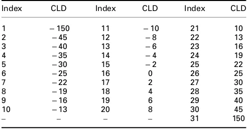
To process more than two audio channels, a number of R-OTT modules are applied in a tree scheme. MPS standard suggests some structures for down-mixing multichannel audio into a mono or stereo audio. For instance, a tree structure used to down-mix 5.1 audio signals, consisting of the left (L), left surround (Ls), right (R), right surround (Rs), centre (C) and low frequency enhancement (LFE) channels, into a mono audio signal is given in Fig. 2, showing that a total of 5 R-OTT modules are employed.
2.2 OTT module
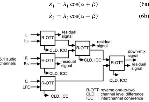
To recreate back both the audio channels, the OTT module utilises the decoded spatial parameters to estimate both the energy constants, ε1 and ε2, using the following method (the indices for the sub-band and parameter band have been ignored for notation simplicity)
ˆ
11 =l1cos(a+b) (6a)
ˆ
12 =l2cos(a−b) (6b)
Fig. 2 Tree scheme of R-OTT modules to down-mix 5.1 audio channels into a single down-mix signal
CLD and ICC, as spatial parameters, are extracted from each R-OTT module and then transmitted as side information of the down-mix signal
Fig. 1 Block diagram of OTT and R-OTT modules
whereλ1andλ2variables are related to each other as below
which is computed based on the decoded CLD,Cˆ. On the other hand, theαvariable is computed as
a=1
which is purely determined from the decoded ICC, Iˆ. Furthermore, theβvariable can be found as
b=tan l2−l1
which is computed from the values of three variables:λ1,λ2 andα. Based on both energy constants, both channels can be reproduced as
which all depend on the decoded down-mix and residual signals as well as the decoded spatial parameters.
2.3 Spatial quantisers
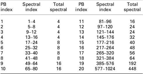
Both CLD and ICC are quantised using non-uniform quantisers. The CLD and ICC, computed from each parameter band, are represented as 5 and 3 bits, respectively. The quantisation values for CLD is given in Table 1, whereas the quantisation values for ICC is presented in Table2.
2.4 Down-mix and residual encoders
The down-mix signal, produced by the tree scheme of R-OTT modules, is subsequently transformed back to time domain for the purpose of encoding using any kind of existing encoder. Additionally, the residual signal is encoded in the same way as in AAC. For this purpose, the sub-band signals must first be transformed to spectral coefficients. A frame of spectral coefficients, comprised of 1024 coefficients, is segmented as scale factor bands, where the number of coefficients within each band is determined based on the bandwidth of the critical bands [4]. As many as 49 scale factor bands are used [21].
For each band, a scale factor is determined, and the spectral coefficients are quantised as follows
ix[k]=sign r[k]nint |r[k]|
whereix[k] is the quantised spectral coefficient with its value is limited from −8191 to + 8191, r[k] is the spectral coefficient of the residual signal and SF is the scale factor. Huffman encoding is then carried out for further compression.
3 Proposed AbS-SAC encoder
The AbS-SAC encoder, that we propose, can be generally explained based on the diagram block given in Fig. 3where a case of encoding 5.1 audio signals is presented. The audio signal in each channel is transformed to spectral coefficients by means of modified discrete cosine transform (MDCT). A tree scheme of closed-loop R-OTT modules, we proposed as an adapted version of R-OTT module, is performed to extract spatial parameters and to down-mix the multiple input signals into a mono audio signal. As opposed to MPS, the AbS-SAC is applied based on MDCT because of a disadvantage of the hybrid QMF when the closed-loop R-OTT module is applied. This is given in more details in the next section regarding the closed-loop R-OTT module.
The down-mix signal is then encoded by a spectral encoder, identical to that employed for residual signals, which actually consists of a spectral coefficient quantiser and a noiseless encoder, as applied in AAC. Used this way, the down-mix signal is prevented from further distortion because of transforming from sub-band domain to time domain in the encoder side and the reverse process in the decoder side. Moreover, as can be seen, four channels of residual signals may be produced when 5.1 audio signals become the input of the AbS-SAC encoder, each of them is encoded individually.
Table 1 CLD quantisation table
Index CLD Index CLD Index CLD
1 −150 11 −10 21 10
Table 2 ICC quantisation table
Index ICC Index ICC
1 −0.99 5 0.60092
2 −0.589 6 0.84118
3 0 7 0.937
4 0.36764 8 1
With the goal offinding sub-optimal spectral coefficients and spatial parameters instead of the optimal ones, an AbS optimisation is performed, employing a block of AbS loop control. This block has a major function to perform simplification of AbS algorithm by mainly reducing the number of possible combinations which results in a much lower number of required iteration compared to a full search AbS algorithm. The AbS loop includes the reconstruction of audio signals and the error calculation between the original audio signals (as target signals) and the reproduced signals, all performed in the frequency domain (i.e. spectral coefficients of audio signals). For the reconstruction of audio signals, the spatial quantisers as well as the down-mix and residual decoders are required within the loop. After completing the AbS optimisation, the selected sub-optimal quantised spectral coefficients and quantised CLD and ICC are transmitted to the decoder. As the simplified AbS algorithm only reduces the number of iterations without affecting any block within the AbS loop, it is possible to apply various level of simplification to achieve the desired quality improvement. This is given in details in the following sections (Fig.4).
3.1 Closed-loop R-OTT module
To apply a closed-loop system, an OTT module should be employed in the encoder side to reconstruct two channels of audio signals, immediately after the R-OTT module. The down-mix channel produced by the R-OTT module is fed directly to the OTT module. Similarly, the spatial parameters and the residual signal are given to the OTT module. As shown in Fig.3, the original two channels can be compared to the reconstructed channels, allowing to measure signal distortion.
Assuming that the mean-squared error (mse) is used as an error criterion, the error signals that are the differences between the original audio signals, x1[n], x2[n], and the
synthesised signals, xˆ
1[n], xˆ2[n], can be written in vector
form as
e1=x1−xˆ1 (13a)
e2=x2−xˆ2 (13b)
and then represented as
e1=x1−1ˆ1yˆ−ˆr (14a) e2=x2−1ˆ2yˆ+ˆr (14b)
by substituting (2). Furthermore, the mses for both channels can be represented as
mse1= x1−1ˆ1ˆy−ˆreT1 (15a)
mse2= x2−1ˆ2ˆy+ˆr
eT2 (15b)
where eT1 andeT2 are the transpose operations of e1 and e2,
respectively.
We assume that each error signal does not have all-zero values, so that the minimum mses for both channels, minimum of mse1 and mse2, can be obtained by requiring every component of (3) to be orthogonal to the corresponding transposed error signal. In the first component, both input signals, x1 and x2, have to be
orthogonal to the corresponding transposed error signals,
eT1 andeT2. These can be written as
x1eT1 =x1xT1−1ˆ1x1ˆyT−x1rˆT=0 (16a) x2eT2 =x2xT2−1ˆ2x2ˆyT+x2rˆT=0 (16b)
which can be simplified as
ˆ
r=x1−1ˆ1yˆ (17a)
ˆ
r=1ˆ2yˆ−x2 (17b)
where the decoded residual signal is represented as two
Fig. 4 Block diagram of the AbS-SAC encoder employing a block of AbS loop control to perform sub-optimal algorithm
different expressions. Using the same method, the second and the third components of (14) will also provide the same equation as (17).
From (17), further simplification can be made where the decoded down-mix signals are represented as
ˆ
which is a requirement that has to be met in order to obtain the minimum mse. It means that the decoded down-mix signal,yˆ,
has to be equal to the sum of both input signals, x1+x2,
divided by the sum of the estimated energy constant,
ˆ
11+1ˆ
2. Based on (17) and (18), the new optimised down-mix signal can be approximated as
ynew=x1+x2
ˆ
11+1ˆ
2
(19)
which results in an approximation error,eapprox, represented as
eapprox=yˆ−ynew (20)
which will strongly affect the quality of the reconstructed audio signals. Moreover, based on the new optimised down-mix signal, (5) can be used to obtain the expression for the new optimised residual signal as below
rnew =x1−1ˆ1ynew=1ˆ2ynew−x2 (21)
where either x1−1ˆ1ynew or 1ˆ2ynew−x2 can be used to
determined rnew. If both input signals have the exact same
magnitude but opposite phases (i.e. x1= −x2), then the down-mix signal has all-zero values, ynew= 0. Consequently, the residual signal can be determined asrnew=
x1= −x2, and a specific information has to be transmitted
to the decoder conveying this information.
If correctly implemented, such that the approximation error is minimum, the closed-loop R-OTT method is capable of completely eliminating the error introduced by the quantisation process of the spatial parameters. This is because the new optimised down-mix and residual signals,
ynew and rnew, are computed based on the estimated energy constants,1ˆ
1+1ˆ2, which depend on the decoded CLD and ICC so that the quantisation errors of CLD and ICC are now compensated for through the newly optimised signals. Consequently, the quantisation errors of CLD and ICC no longer affect the overall distortion of the synthesised audio signals.
However, the operation of the closed-loop R-OTT method in the sub-band domain of the hybrid QMF is not always appropriate for applying the proposed closed-loop R-OTT module. The hybrid QMF has a disadvantage when applied to the closed-loop R-OTT module, because the impulse responses of the analysis filter-bank are different from the impulse responses of the synthesis filter-bank, leading to a dissimilarity in the length of delay introduced. The analysis
filter-bank introduces a delay of 704 samples, which is equivalent to 11 samples in the QMF sub-band domain. On the other hand, the synthesis filter-bank introduces a delay of 257 samples, which is equal to 4.015625 samples in the QMF sub-band domain [20]. As a result of fractional sample delay of the 0.015625 sample, it is not possible to match the synthesised and target signals properly, leading to a less than perfect comparison.
It is therefore necessary to use another time-frequency transformation for employing the closed-loop R-OTT module. Although there are various signal transformations available that may be suitable, we propose applying the closed-loop R-OTT module in the MDCT domain. In addition to its ability to meet the requirement in (19) and (21), applying the MDCT-based R-OTT module avoids the need for the transformation of the residual signals from the sub-band domain of filter-bank to spectral coefficients for the purpose of quantisation, as in the case of MPS. Thus, it can simplify the structure of the encoder. Moreover, the MDCT transform also provides a perfect signal reconstruction. Please note that applying the open-loop R-OTT module in the MDCT domain possibly leads to strong artifacts in the reconstructed audio signals. It is only the closed-loop version of the R-OTT module that is proposed for implementation in the MDCT domain.
3.2 Parameter band
The parameter bands in the proposed AbS-SAC are determined with the purpose to keep the frequency resolution of each parameter band to be identical to the one applied in MPS. However, it is also necessary to consider that in performing quantisation, the spectral coefficients are grouped into 49 scale factor bands. It is therefore more effective to group a single or a number of spectral bands as a parameter band, instead of directly grouping the spectral coefficients. In order to take this into consideration, the parameter bands can be determined by mapping the 71 hybrid bands of the hybrid QMF to the 49 scale factor bands of the spectral coefficients. Depending on the number of the parameter bands, various methods of mapping the hybrid bands to the scale factor bands present themselves. For instance, such a mapping for grouping 49 scale factor bands to 20 parameter bands results in a grouping of several spectral coefficients (shown by spectral index) into 20 parameter bands (PB index) as given in Table3.
3.3 Sub-optimal AbS optimisation
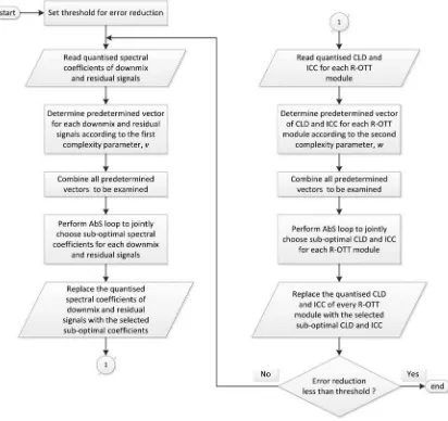
The goal of this sub-optimal algorithm is not to provide the optimal or near-optimal signals and parameters. Instead, it is intended to provide a solution for the practical implementation of the optimal searching procedure while minimising the signal distortion. The flowchart of the sub-optimal algorithm is given in Fig. 5. First, a threshold for error reduction should be given. Then, the quantised spectral coefficients of the down-mix and residual signals are used as initial inputs to calculate predetermined vectors
based on (22). These vectors can be combined to provide multiple possible combinations of spectral coefficients which will be examined to jointly choose sub-optimal spectral coefficients which result in minimum mse. The identical procedure can be applied to choose sub-optimal CLD and ICC. If the error reduction is still greater than the given threshold then the above process is repeated. Otherwise, the sub-optimal spectral coefficients of the down-mix and residual signals along with the sub-optimal CLD and ICC are represented as bitstream and transmitted to the decoder.
A number of quantisation values defined as the candidates for sub-optimal spectral coefficient named as predetermined vector, ixp[k], can be assigned based on the quantised spectral coefficients,ix[k], as
ixp[k]=[ix[k]−v, . . ., ix[k], . . ., ix[k]+v] (22)
whereix[k] is the quantised spectral coefficient as in (15),kis the index of spectral coefficient and 2υ+ 1 is the size of the predetermined vector, ixp[k], with υ an integer number reflecting the computational complexity of the searching procedure. Likewise, a limited number of quantisation values of spatial parameters are determined in a similar way. The CLDs and ICCs obtained from the quantisers are used as the initial values. A set of predetermined values of channel level differences, Cp, and a set of predetermined
values of inter channel coherences,Ip, are determined, using
Pp= P pb−w
, . . ., P p
b
, . . ., P p
b+w
(23)
whereP(pb) is the initial quantised parameter,Pis the spatial parameter which is eitherC, orI,pbis the index of the initial quantised parameter, w is an integer number reflecting the complexity of the procedure. For CLD w≤15 and for ICC
w≤3 whilebis the index of the parameter band.
4 Results
To evaluate the proposed system, a number of experiments designed to assess the encoding of five and ten audio channels were conducted. The audio excerpts, sampled at 48 kHz, listed in Table4were prepared for the experiments. They were selectively chosen from a broad range of long sequence 5.1 audio signals ranging from speeches, pop and classical music, as well as specific sounds such as clapping hands. For each audio sequence, a limited 12 s audio excerpt was selected based on the possibility of more transient events. All of the ten-channel audio signals were produced by up-mixing the five-channel signals using a simple amplitude panning technique. The tree scheme of R-OTT modules for down-mixing five channels into a mono down-mix, as given in Fig. 2, was used in the experiments. However, the LFE channel was excluded for
simplicity. Each channel of audio signals was segmented into 2048 time domain samples with 50% overlap. The down-mix signal was encoded by AAC. The AAC multichannel codec, implemented as FAAC 1.28 and FAAD2 2.7 [22], was used for benchmarking to demonstrate the usefulness of the proposed AbS-SAC approach, even though it is not the best implementation of the AAC standard.
4.1 SNR measurement
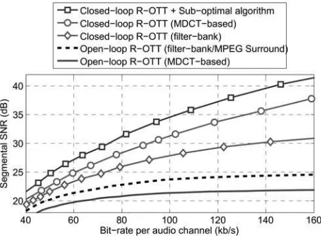
This section presents the experiments conducted to evaluate the overall performance of the proposed AbS-SAC for various bit-rates. The sub-optimal algorithm is performed using the lowest complexity, where υ= 1 and w= 1. The conventional R-OTT module, as well as the closed-loop R-OTT performed in both the sub-band and the frequency domain are included for benchmarking. The results are given in Fig. 6. The figure shows that, both the proposed techniques: closed-loop R-OTT module and sub-optimal algorithm, contribute to the improvement of segSNR. It indicates that the proposed AbS-SAC technique achieves significant higher segSNRs, compared with MPS, at bit-rates above 40 kb/s per audio channel. The improvement tends to become higher as the bit-rate increases.
4.2 Perceptual objective test
The goal of this experiments is to estimate perceptual quality of the proposed AbS-SAC for various operating bit-rates. To our knowledge, no objective perceptual test is currently available for high quality multichannel audio signals. Thus, we have adapted the perceptual evaluation of audio quality (PEAQ) [23], an ITU-R BS.1387-1 recommendation for assessing a mono audio signal, and currently under standardisation process to include multichannel audio assessment [24], for multichannel audio signals. The
objective difference grade (ODG), that has five grades: 0 (imperceptible), −1 (perceptible but not annoying), −2 (slightly annoying), −3 (annoying) and −4 (very annoying), was first measured for each channel of audio signal. The average values of the ODG scores over all channels are then presented as the final results for multichannel audio. A software developed by McGill University [25] is used for calculating ODG score. Moreover, the experiments also include encoding of ten-channel audio signals. This is intended to show that, for larger channels at the given bit-rate per audio channel, the performance improvement is even higher. Considering the complexity of the AbS-SAC encoder, for encoding five audio channels, the sub-optimal algorithm is assigned with υ= 1 and w= 1, whereas for encoding ten audio channels, parameters are set to υ= 1 andw= 0.
The results of the experiments for encoding five-channel and ten-channel audio signals are given in Fig. 7. For simplicity, the results of AAC ten-channel are not shown, as they are almost identical to those achieved on AAC
five-channel. The overall ODG, averaged over all audio excerpts as shown in the lowest right plot, shows that the AbS-SAC, applied to both five and ten channels, significantly outperforms, in terms of PEAQ, the tested AAC multichannel for all operating bit-rates from 40 to 96 kb/s per audio channel. However, the performance increase is greater when encoding ten channels. It can be seen that an improvements of more than a point of ODG grade are achieved at bit-rates between 40 and 48 kb/s per audio channel. The results indicate that the proposed AbS-SAC technique significantly improves encoding performance for a wide range of tested audio materials.
4.3 Subjective test
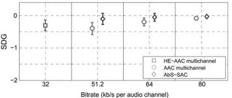
The proposed AbS-SAC approach, for encodingfive-channel audio signals, has also been evaluated using listening tests. The subjective assessment of small impairments in the audio system, as recommended in the ITU-R BS.1116-1 [26] using the ‘double-blind triple stimulus with a hidden reference’ method, is used. The subjective difference grade (SDG), having five grades that are similar to ODG, is used. Three codecs were taken under test: AbS-SAC, AAC multichannel and HE-AAC multichannel.
In the experiments, three bit-rates of 51.2, 64 and 80 kb/s per audio channel are chosen for both the AbS-SAC and AAC multichannel. Moreover, the HE-AAC multichannel operates at its maximum typical bit-rate of 32 kb/s per audio channel, which is equal to 160 kb/s for all five audio
Fig. 6 Performance of the proposed techniques: closed-loop R-OTT and sub-optimal algorithm
Fig. 7 ODG of the AbS-SAC for various bit-rates in comparison with the tested AAC multichannel
The ODG scores of the tested AAC multichannel, for encoding ten-channel audio signals, are not plotted as they are similar to the ODG scores of the tested AAC multichannel for encodingfive-channel audio signals
Table 4 List of audio excerpts for experiments
Excerpt name Description
channels. Operating the HE-AAC above this bit-rate is not useful in terms of coding efficiency, which means that the HE-AAC multichannel may not achieve a better performance [27].
A total of 20 listeners participated in this listening test. As specified in [26] the expertise of the listeners are evaluated by averaging their SDG scores over all audio excerpts. Based on this average SDG score, a post-screening method was applied. Three listeners with an average SDG score greater than zero are assumed to be unable to correctly distinguish between the hidden reference and the tested audio object. Thus, the data from those three listeners was discarded. Only the SDG scores from the other 17 listeners were used for the results. Fig. 8 presents the average SDG score of each tested audio codec averaged over all audio excerpts. The error bars show the 95% confidence intervals of the mean scores. The results show that the SDG scores of all the tested codecs are competitive and very close to a grade of imperceptible. However, the proposed AbS-SAC approach achieves the highest SDG score.
5 Conclusions
A new SAC technique based on the principle of closed-loop system is presented in this paper, proposing a closed-loop R-OTT module as well as an algorithm for selecting sub-optimal signals and parameters. The proposed closed-loop R-OTT module is applicable for implementation either in the sub-band domain of afilter-bank, as in the case of hybrid QMF applied in MPS, or in the frequency domain using MDCT transform. On the other hand, the sub-optimal algorithm addresses the impracticality of the optimal AbS optimisation. Moreover, it offers a complexity scalability, providing a trade-off between the complexity of the encoder and the quality of the reconstructed audio signals.
The experimental results, for encodingfive-channel audio signals at bit-rates ranging from 40 to 96 kb/s per audio channel using two reasonable complexity levels of the encoder, demonstrate that significant improvement of objective performances, in terms of segSNR and ODG scores, is achieved compared with the conventional open-loop techniques. At the lowest complexity level, the encoder is capable of working in a real-time implementation, while at a higher complexity level, the computation time increases approximately 72 times. In addition, subjective evaluation at the tested bit-rate also shows that the proposed AbS-SAC scheme provides a higher SDG score. Moreover, the experiments also indicate that, for encoding a higher number of input channels, the objective performance, in terms of ODG score, can improve even further.
6 Acknowledgments
This work was supported by the ROMEO project (grant number: 287896), which was funded by the EC FP7 ICT collaborative research programme. The authors would like to thank the anonymous reviewers for their constructive comments and suggestions to improve this paper.
7 References
1 Herre, J., Faller, C., Disch, S., et al: ‘Spatial audio coding: next-generation efficient and compatible coding of multi-channel audio’. Presented at the 117th Convention of the Audio Engineering Society, San Fransisco, CA, USA, October 2004
2 Herre, J., Disch, S.:‘New concepts in parametric coding of spatial audio: from SAC to SAOC’. Proc. IEEE Int. Conf. Multimedia and Expo, San Fransisco, CA, USA, October 2007, pp. 1894–1897
3 Blauert, J.: ‘Spatial hearing: the psychophysics of human sound localization’(MIT Press, 1983, Rev. ed. 1997)
4 Munkong, R., Juang, B.: ‘Auditory perception and cognition’, IEEE Signal Process. Mag., 2008,25, (3), pp. 98–117
5 Baumgarte, F., Faller, C.:‘Binaural cue coding-Part I: psychoacoustic fundamentals and design principles’, IEEE Trans. Speech Audio Process., 2003,11, (6), pp. 509–519
6 Faller, C., Baumgarte, F.:‘Binaural cue coding-Part II: schemes and applications’,IEEE Trans. Speech Audio Process., 2003,11, (6), pp. 520–531
7 Herre, J., Faller, C., Ertel, C., Hilpert, J., Hoelzer, A., Spenger, C.:‘MP3 surround: efficient and compatible coding of multi-channel audio’. Presented at the 116th Convention of the Audio Engineering Society, Berlin, Germany, May 2004
8 Moon, H.:‘A low-complexity design for an mp3 multichannel audio decoding system’,IEEE Trans. Audio, Speech, Lang. Proc., 2012,20, (1), pp. 314–321
9 Schuijers, E., Breebaart, J., Purnhagen, H., Engdegard, J.: ‘Low complexity parametric stereo coding’. Presented at the 116th Convention of the Audio Engineering Society, Berlin, Germany, May 2004
10 Breebaart, J., van de Par, S., Kohlrausch, A., Schuijers, E.:‘Parametric coding of stereo audio’,EURASIP J. Appl. Signal Process., 2005,9, pp. 1305–1322
11 Roden, J., Breebart, J., Hilpert, J.,et al:‘A study of the MPEG Surround quality versus bit-rate curve’. Presented at the 123th Convention of the Audio Engineering Society, New York, USA, October 2007
12 Hotho, G., Villemoes, L., Breebaart, J.: ‘A backward-compatible multichannel audio codec’, IEEE Trans. Audio, Speech, Lang. Process., 2008,16, (1), pp. 83–93
13 Herre, J., Kjorling, K., Breebaart, J.,et al:‘MPEG Surround–the ISO/ MPEG standard for efficient and compatible multichannel audio coding’,J. Audio Eng. Soc., 2008,56, (11), pp. 932–955
14 Hilpert, J., Disch, S.: ‘The MPEG Surround audio coding standard [Standards in a nutshell]’,IEEE Signal Process. Mag., 2009,26, (1), pp. 148–152
15 Wolters, M., Kjorling, K., Homm, D., Purnhagen, H.:‘A closer look into MPEG-4 high efficiency AAC’. Presented at the 115th Convention of the Audio Engineering Society, New York, USA, October 2003 16 Herre, J., Dietz, M.:‘MPEG-4 high-efficiency AAC coding [Standards
in a nutshell]’,IEEE Signal Process. Mag., 2008,25, (3), pp. 137–142 17 Breebaart, J., Hotho, G., Koppens, J., Schuijers, E., Oomen, W., van de Par, S.:‘Background, concepts, and architecture for the recent MPEG Surround standard on multichannel audio compression’,J. Audio Eng. Soc., 2007,55, (5), pp. 331–351
18 Elftri, I., Gunel, B., Kondoz, A.:‘Multichannel audio coding based on analysis by synthesis’,Proc. IEEE, 2011,99, (4), pp. 657–670 19 Elftri, I., Kondoz, A., Gunel, B.: ‘Spatial audio coding’. UK Patent
2485979, June 2012
20 ISO/IEC 23003-1: ‘Information technology – MPEG audio
technologies–Part 1: MPEG Surround’, 2007
21 ISO/IEC 14496-3:‘Information technology–Coding of audio-visual objects–Part 3: Audio’, 2009
22 http//xwww.audiocoding.com, accessed December 2012
23 ITU-R BS.1387-1:‘Method for objective measurements of perceived audio quality’, 2001
24 Liebetrau, J., Sporer, T., Kampf, S., Schneider, S.:‘Standardization of PEAQ-MC: Extension of ITU-R BS.1387.1 to multichannel audio’. Presented at AES 40th Int. Conf, Spatial Audio: Sense the Sound of Space, Tokyo, Japan, October 2010
25 Kabal, P.: ‘An examination and interpretation of ITU-R BS.1387: perceptual evaluation of audio quality’, Telecommunication and Signal Processing Laboratory, Department of Electrical and Computer Engineering, McGill University (URL: http://www-mmsp.ece.mcgill. ca/documents/Software/)