Cellular Multihop Networks: State of the Art
Teddy Sutanto Tarsono
1), Aditya Umbu Tana Amah
2)1)Institute of Communication Networks and Computer Engineering, University of Stuttgart
Pfaffenwaldring 47, 70569 Stuttgart, Germany. email: [email protected]
2)
Department of Electrical Engineering, Petra Christian University, Jl. Siwalankerto 121-131 Surabaya 60236 email:[email protected]
Abstract
This paper presents the summary of some research in the area of cellular multihop networks that contains the improvement in network performance also the difficulties and the complexities of the networks. The combination of two different networks, mobile cellular networks and WLAN ad hoc networks will be presented. The main purpose of the combination is to minimize the weaknesses of both network types when they are deployed separately. By having this combination then it is possible to provide higher mobility for WLAN ad hoc networks user and higher data transfer rate for cellular network users in multimedia applications. The cellular multihop networks will reduce blocking probability, balance the cells load and increase the network capacities. Although there are improvement on the performance of the combine networks, but there are additional aspects that should be considered seriously, especially for WLAN ad hoc users. Authentication, Authorization and Accounting (AAA) functions, the dynamic routing and relay path discovery, maintenance and security issues are aspects to be considered for cellular multihop network.
Keywords: cellular networks, ad hoc networks, multihop networks, WLAN, routing.
Abstrak
Paper ini merupakan ringkasan dari beberapa penelitian di bidang cellular multihop networks dengan pemaparan pada peningkatan unjuk kerja jaringan dan kesulitan serta kompleksitas jaringan. Penggabungan dari dua jaringan yang berbeda antara jaringan Mobile Cellular dengan jaringan WLAN ad hoc akan dipaparkan. Tujuan utama dari penggabungan ini adalah untuk meminimalkan kekurangan kedua jaringan saat diimplementasikan secara terpisah. Penggabungan ini memungkinkan pergerakan yang lebih luas bagi pengguna jaringan WLAN ad hoc dan laju transfer data yang tinggi untuk pengguna jaringan seluler. Peningkatan lainnya adalah adanya pengurangqn probabilitas blocking, penyeimbangan beban sel-sel dan peningkatan kapasitas jaringan. Walau terdapat peningkatan pada unjuk kerja melalui penggabungan kedua sistem tersebut, terdapat pula aspek-aspek yang tetap harus diperhatikan secara serius, terutama bagi pengguna jaringan WLAN ad hoc. Fungsi Authentication, Authorization and Accounting (AAA), dynamic routing dan relay path discovery, pemeliharaan serta keamanan merupakan aspek-aspek yang harus diperhitungkan pada jaringan Cellular Multihop.
Kata kunci : cellular networks, ad hoc networks, multihop networks, WLAN, routing.
1. Introduction
Mobile cellular communications for voice service and Wireless LAN for data service have becoming two major technologies for voice and data communication nowadays. Nevertheless, they still have some weaknesses in several aspects. Mobile cellular networks have very low bit rate for data service while, on the other hand, WLAN technology in the point of view of the user has limited mobility because of small coverage of its access points. Some researches in
Note: discussion is expected before December 1st 2004. The proper discussion will be published in Journal of Electrical Engineering Vol. 5, No. 1, March 2005.
each of these respective technologies have been done to improve the performance of both technologies and reduce their weaknesses.
mobility of users is getting higher because they can communicate to each other without a fixed infrastructure such as fixed mounted access points. However, it is not possible to have an internet connection if there is not at least one client which has internet connection to the fixed infrastructure.
Figure 1. Basic Idea of Cellular Multihop Networks [1]
Figure 1 shows the problems and the idea of how the cellular networks can be enhanced to give higher performance and availability to the users also higher efficiency and usability to the networks. The integration of cellular and WLAN technologies is one of innovative ideas for this purpose.
Relaying is one of the enhancements that cellular system may use to improve coverage and robustness against network failure or radio link failure, to provide interoperability between heterogeneous systems and to increase capacity by lowering transmission powers and associated intercell interference with negligible increase to mobile station’s complexity or cost. Compare to the future UMTS that offers a global mobility, GSM offers similar mobility with some constraints in capacity and coverage. It has shown from some experiments that the integration of satellite-GSM communication provides global roaming, whereas the integration between DECT-GSM networks improves indoor coverage. Nevertheless, there still ‘dead spots’ such as in subway train platform that makes the integrated system fails to have an effective communication. It is not economical to install such an expensive additional antenna for each ‘dead spot’. To this end, the standard GSM radio interface needs to be extended with sufficiently flexible capabilities to support relaying to become an A-GSM (ad hoc GSM). [1] [2]
The purpose of this paper is summarizing the state of the art of ad hoc networks and cellular multihop networks. This paper is a continuation of some topics such as [2] and [3]. As a continuation of those topics, this paper will be a report of the development progress in cellular multihop technologies.
The outline of this paper will be as follows: introduction, basic architecture of cellular and WLAN ad hoc networks, the advantages of integration of cellular and ad hoc networks, proposed architecture from some researches and conclusion. The intention of this paper will be in routing concepts, vertical and horizontal handover and some aspects from user point of view.
2.
Basic Architecture of Cellular Multihop NetworksThis section gives brief explanations of the basic architecture of cellular networks, ad hoc networks, and cellular multihop networks. The subsection of cellular networks discusses the second and third generation mobile communications networks especially the service for data transfer. The subsection of Wireless LAN and Ad hoc network discusses the basic concepts of WLAN in infrastructure mode and ad hoc mode.
2.1 Cellular Networks
This section will emphasize the data communications in cellular network and the explanation will go directly to the 2.5G networks architecture (GERAN: GSM/GPRS/EDGE) and the integration of 3G networks (UMTS) with intention to the radio access networks (RAN). The reason is because data service in 2G network is available only with traditional circuit switched technology and very limited data rate (9.6 kbps) which is not sufficient for many applications that require much higher data rate. Higher data transfer rate in cellular networks can be achieved through EDGE, GPRS, and UMTS technology.
Access Network Core Network
Figure 2. 3G Networks Architecture (GERAN+UMTS) [4]
The circuit-switched core network is based on circuit-switched ISDN technology with signaling system number 7 as a communication protocol between two networks components. It provides circuit-switched services (voice and data) and supports mobility management of the user (e.g. location management and handover). It usually built by several nodes such as Mobile Switching Center (MSC), Visitor Location Register (VLR) and Home Location Register (HLR). In addition a so called Intelligent Network (IN) concept within Service Control Point (SCP) node is introduced to provide Value Added Service to the users (prepaid service, hot-line service, virtual private network, home zone billing, tele-voting, etc.).
The packet-switched core network has connections to an external packet data network (an IP based network) and hides the mobility of the mobile station from that external packet data network. It usually consists of Serving GPRS Support Node (SGSN), Gateway GPRS Support Node (GGSN) and Border Gateway (BG) for interconnecting of GSNs to other operators. Similar to the circuit-switched core network, it serves mobile station within its service area to perform authentication, mobility management and session management, e.g. packet data protocol context activation, including of the assignment of an IP address. GGSN interfaces the packets of its users to the external packet data network.
GERAN and UTRAN are the part where the user can access the network and this part is called Access Network. In the 2.5G access network, the base station already has feature of processing in TDM (Time Division Multiplex), ATM
(Asynchronous Transfer Mode) and IP (Internet Protocol) based.
The radio equipment of GERAN is called BSS (Base Station Subsystem). It can support one or more cells, and consists of one BSC (Base Station Controller) and one or more BTS (Base Transceiver System). A BSC controls one or more BTS, and a BTS is connected to users through the radio interface. Like GERAN, the radio equipment of UTRAN is called RNS (Radio Network Subsystem). It consists of an RNC (Radio Network Controller) and one or more Node Bs.
There is a function splitting between BSS and core network. The basic task of GSM BSS is to provide bearer service to user like ISDN B- and D-channels. All radio-related function is handled by BSS. On the other hand all subscriber- and service-related functions are handled by core network. Mobility-related functions are handled by BSS and core network. After GPRS is introduced, some function like logical link control is put into the SGSNs.
Unlike BSC, there are two types of RNC, i.e. Controlling RNC and Serving RNC or Drift RNC. CRNC control all logical resources of the cells or Node Bs and there is only one SRNC for each User Equipment (UE) that is connected to UTRAN. DRNC is when a connection between the UTRAN and UE need to use one or more cells controlled by this RNC is called.
Function splitting between UTRAN and its core network is much like GSM/GPRS in non-access related signaling like Connection Control, GPRS Mobility management, and Session Management. But because of the purpose of UTRAN is not only for voice processing, some functions like Quality of Service (QoS) measurement, radio and logical link control is shifted from core network to access network.
2.2 Wireless LAN and Ad hoc Networks
emerging generation, with higher data transfer rate and similar technology to HiperLAN in Europe. The new standard is IEEE 802.11g with data transfer rates up to 54 Mbps. Here the term of WLAN 802.11 is used as a general term.
There are two operation mode of WLAN networks, i.e. Infrastructure Mode and Ad hoc Mode. Infrastructure mode contains Access Point (AP) and Stations (nodes). Each of the nodes is associated to at most one AP. The cell radius is around 100 until 300 meters. The connection between AP and node is like a star configuration in wired network. The function of AP is like BSS in the cellular networks, as a bridge between nodes and wired LAN.
Ad hoc mode is also called Basic Service Set (BSS). It consists of two or more nodes, which have recognized each other and have established peer to peer communications within the given coverage area of each antenna. Because of mobility of the users, this type of network is often formed only for temporary basis and is commonly also referred to Independent BSS [5].
Some important term explained in the following paragraphs are used in ad hoc networks [3] that characterize this network architecture. Every node is using Internet Protocol (IP) to communicate each others and Access Point. Any nodes may change their position and link connectivity at any times. The network is based on packet switching and the devices get IP addresses by common methods [6]. There are no fixed infrastructure and each node work in distributed operation. Every node must have capability of self-organized to establish and release route to different destination of other nodes dynamically
One node may be not within the direct wireless transmission range to other nodes. In this case it needs one or more intermediate nodes to forward packet between two nodes. This feature is called multihop network, which needs a special routing algorithm, to decide which adjacent nodes is chosen to forward its packets. It is necessary that each node can be an end point or intermediate point of a communication link. The nodes must assist each other in sending information as autonomous nodes.
Each node in ad hoc network can move arbitrarily. The interconnection between two
nodes can be established and released any time. This condition constructs a dynamic topology of network architecture. Some studies and researches are done to support this requirement. Other aspect that should be observed regarding to the dynamic position of nodes are the variable bandwidth and link capacity.
One important point of ad hoc networks is that communication between nodes contains more control data to establish and release routes and decrease the link efficiency of the communi-cation channel to transmit the user data (pay load). The increasing amount of transmitting control data affect to the needs of more battery power. Routing mechanism should be very efficient to optimize the message processing and reduce the power consumption.
As a consequence of using air interface there is difficulties in protecting the link between nodes to have a secure link. It becomes more complicated in ad hoc network because every node can establish a connection to any other nodes and they have distributed operations. There are some protocols and encryption algorithms that have been developed and tested for this purpose [3] [7].
3. Integration of Mobile Cellular Network
and WLAN Ad Hoc Network
Cellular networks have a weakness for having very limited data transfer for data communications. With this limitation, some applications with higher data rate requirement can not be implemented. Examples of these applications are multimedia messaging which has bigger message size comparing to Short Message Service (SMS) and video-conference which uses data audio and video for real time communications. However, in cellular network the user can have high mobility capability because currently the cellular networks have covered almost all of the area where peoples do their daily activities. The problems usually arise only in the border of cell or in shadowed area.
With the idea to trade the advantages and the disadvantages of both networks, some researchers have tried to integrate them into one network. Figure 3 shows one of the proposed networks based on IP technology [4]. It is called IP Multimedia Subsystem (IMS) from UMTS Release 5. It is a combination of 2.5G cellular network (GSM/GPRS/EDGE), 3G cellular network (UMTS) and WLAN 802.11 tech-nologies. Some new networks nodes is introduced to be able to work in several type of access network, so the packet data from one access network can be forwarded/ received to/from other type of access network.
Figure 3. Integration of Cellular Network and WLAN Ad hoc Network Architecture [4]
Some final objectives that should be achieved by implementing this complicated network are:
• The users who are located in the blank spots of cellular networks like in the cell border, in the area of deep fading eg. behind a building, in a tunnel, in the underground train, and in the area where high interference blocks the cellular signal, can still establish a call connection. [8]
• The users in a hot cell, where there is no free cellular channel, can still establish a call by using WLAN channel. The benefits of this ability are: call blocking probability of the networks is decreased, there is a load balancing between hot cells and cold cells, cellular and WLAN channel can be used more efficiently. [9]
• The users of cellular networks can have higher data transfer rata when using the WLAN channel and infrastructure.
• The users of WLAN networks can be more mobile and still maintain their connection to the networks because the connection is relayed from one cell to another cell of cellular networks.
• Because of load balancing and higher efficiency of networks usage, it is obvious that networks have higher capacity.
4. Proposed Implementation of Cellular
Multihop Architectures
There are several groups of researches that have submitted proposals of the implementation of Cellular Multihop Architecture. In the following subsections, each proposal will be explained including the proposed network architectures, the intention and purpose of the researches, advantages and disadvantages of proposed solutions, analysis of the result of the researches. The HCMN system gives an overview of complete network architecture. The UCAN system provides more information of algorithm of routing and relay path discovery and maintenance. The iCAR system gives more intention to the allocation of fixed ARSs. The PARCelS enhances the protocol, and achieves higher performance of getting more load-balance network with mobile relay nodes. The CAMA system introduces CAMA agents as a dedicated centralized controller of mobile ad hoc nodes.
4.1 Hierarchical Cellular Multihop Networks [10, 11]
Wireless LAN in the lowest layer in infrastructure mode provides high-speed access in hot-spot areas to connect to the Internet. In ad hoc mode mobile nodes can also be a self-organized networks. In this mode nodes can communicate each other without the existing of infrastructure. It communicates each other by using its adjacent nodes as relays. This interaction method builds a multihop commu-nication.
Figure 4. Hierarchical Cellular Multihop Network Architecture [10]
Differ from ad hoc mode capability of WLAN network nodes, cellular nodes really depend on a fixed infrastructure i.e. base station (BS). It also requires more complex radio-network-planning and operates in licensed radio spectrums. The 3rd generation of cellular network, UMTS theoretically can provide a data transfer rates up to 2Mbps, but practically it is still limited to 384 kbps. This data transfer rate is not enough for very high number of mobile node users in a hot-spot area.
WLAN is introduced in the lowest layer to increase the individual data rate of users. The last technology of WLAN IEEE 802.11g systems can provide transmission rates up to 54 Mbps. This system operates in unlicensed radio frequency spectrums. Compared to cellular network this system also has advantages in very low required cost.
To be able to use several types of networks, the mobile nodes must have capability in using several interface i.e. different frequency band and modulation technique. The other requirement is that a protocol must be design to be implemented in all layers of the networks and in
the mobile nodes to enable a Vertical Handover procedure between different network layers.
All the nodes activities are controlled by Base Station which has access to the backbone (core networks). It uses TCP/IP based protocol suite. In the case that higher data transfer rate is required, Wireless LAN systems can provide a broadband radio access for nodes from Access Points (APs).
Practically, the cellular network coverage always has several blank spots because lack of signal power when signal from BSs or APs to the nodes is shadowed by an object. This problem can be solved by introducing multihop capable nodes (MHN) or extension point (EP), which can be fixed or mobile. They can be either dedicated relay nodes or the other mobile nodes. With the fixed MHNs the coverage area of the BSs and APs can be extended to reach the blank spots.
(a)
(b)
Figure 5. Typical hot spot scenario for public places with fixed MHNs (EP) [11]
can also be connected to a power supply to offer more reliable services. Mobile MHN has disadvantage of more complex routing protocol to forward the message from one node to the other node.
Either fixed MHNs or mobile MHNs can establish new sub-cells which supports self-organized networks nodes. The control of its sub-cell can be taken by MHN from its recognized AP. It also provides the connections between nodes in the sub-cell, which can directly communicate with each other. In this case overall control information still come from the higher network layer, e.g. routing information that are provided by a BS, to support mobility to the users.
More detail technical aspect of transmit power and capacity analysis, and proposed routing protocol of multihop networks like Dynamic Source Routing (DSR) and Ad hoc On-Demand Distance Vector (AODV) can be found in [10] [11]. As a summary, the benefits that can be achieved are:
1. Access Point coverage area is extended by fixed and mobile MHNs / EPs.
2. Transmit power of mobile nodes is reduced, because MN can use low-power link of smaller cell instead of larger cell area. It is resulting in longer standby time of MN. Nevertheless the relaying required power consumption and relay delay time should be still considered.
3. Higher system capacity can be expected by implementing scheduling and resource allocation protocol.
4. Lowest layer architecture i.e. WLAN network deployment has lower cost than higher layer networks.
5. Optimized resource control can be achieved by centralized and hierarchical control in BS, AP and MHNs.
4.2 UCAN: Unified Cellular and Ad-hoc Network [12]
4.2.1 Network Architecture
The network architecture of UCAN is quite similar to the HCMN in the previous section. It consists of a 3G wide-area network i.e. High Data Rate of UMTS and WLAN IEEE 802.11b. These two technologies are chosen because of their support for high data rate and their
popularity. It is assumed that each device in UCAN has dual wireless interfaces: HDR and IEEE 802.11b. It can be a portable device which is supported by both 3G wireless modem and IEEE 802.11b WLAN interface. Figure 6 shows this architecture more clearly. Beside of introducing the network architecture, the paper also gives more intention to the routing and protocol how the proxy and relay client can be found, and how the packet data is forwarded.
Figure 6. Unified Cellular and Ad-hoc Network (UCAN) Architecture [12]
This architecture is based on similar observations of HCMN i.e. the network is expected to be able to provide "always-on" availability of the majority of Internet applications, peer-to-peer communication feature of WLAN IEEE 802.11b in ad-hoc mode that is cost effective, IEEE 802.11b standard defines significantly higher-bandwidth wireless communication (up to 11 Mbps within limited range) than existing 3G wide-area wireless technology.
There is limitation of IEEE 802.11b ad-hoc networks due to the unreliable connectivity of client with high mobility and potential interferences problem in the license-free frequency band. Because their high-bandwidth links is only used within a local area, it is expected to be able to improve quality of access of the user to the wide area cellular network.
In the normal way, mobile devices are associated with the HDR base station. Some of them may use HDR downlink to receive data packets from the Internet with high data rate. Associated devices as clients, maintain their downlink channel data rate by monitoring the pilot bursts of the HDR downlink. If it is necessary these devices turn on their IEEE 802.11b interfaces in ad-hoc mode, and run UCAN protocols before they experiences too low HDR downlink channel rate (e.g., 38.6Kbps). To maintain the high data
rate, the HDR base station relays the data frames to another client (proxy client) which has a better channel rate (e.g. up to 2.4Mbps). These data frames are then further relayed through IP tunneling by these intermediate relay clients to the destination, using the high-bandwidth IEEE 802.11b links. Figure 8 also shows this relaying algorithm in a multihop cellular network architecture.
Table 2. Throughput with/without relay [12]
3G Mode Signal Strength Average Throughput
Maximum Thoughput
No Relay -96 to -105 dBm 51.6 Kbps 95Kbps
Relay -78 to -80 dBm 93.9 Kbps 130Kbps
Table 2 gives the result of some experiments that shows that there is a improvement of network performance after introducing proxy and relay client. In this case network performance is measured by using two parameters i.e. signal strength and data transfer rata (throughput). In the relay mode, signal strength can be decreased ca. 20 dBm, and data transfer rate is increased ca. 40 Kbps. Decreasing of signal strength helps the UMTS network to be able to have more users in its network coverage area.
4.2.2 Proxy Discovery and Routing Protocol
The following paragraphs will give more intention to the proxy discovery and routing protocol. A mobile device which experiences low HDR downlink channel rate will send out a route request message to the adjacents devices using its IEEE 802.11b interface. This route request message can reach the base station through several intermediate mobile clients, which are called relay clients. Base station then will try to reach a mobile client close to it, which is called proxy client, and still have high HDR downlink channel rate. The route information requested by destination client is translated from each relay client in the same path before but in the reverse order. And it will be simultaneously forwarded through the clients to reach back the destination clients. In this algorithm, the proxy discovery protocol also serves as the route establishment protocol.
After this multihop connection can be established and known by the destination client, the proxy client then sends a proxy application message to the HDR base station by using the HDR uplink. The HDR base station also updates the proxy
table entry for the destination client. The HDR base station then start to transmit data frames to the proxy client, in the next scheduled time slot for the destination client. The proxy client then will checks the destination signature field of the frame and forwards it to the destination client by using its IEEE 802.11b interface. In this case IP tunneling is used to encapsulate the data frame in an IP packet.
This paper presents two proxies discovery protocols: Greedy and On demand. In the greedy protocol, all clients proactively maintain average downlink channel rates of their immediate neighbors. When the route request message is issued, it will be unicast only to the neighbor with the highest downlink channel rate. The message then is traverses greedily through a set of relay clients which have increasing downlink channel quality to the proxy client and then to the HDR base station as the end point. In the on-demand protocol, when a mobile client initiates a route request message, it floods the message to all its neighbors within a given range. Those neighbors which have high channel quality and might serve as the proxy will reactively send application messages to the HDR base station. These two protocols may find different proxies, have different overhead on the 802.11b network and the HDR uplink.
Figure 7.a shows an example of Greedy Proxy Discovery and Routing. The destination client A initiates a RTREQ (Route Request) to client B which has direct link to client D. In this case client D is a proxy client, because it has no neighbors with better HDR downlink channel rate. Then it sends a proxy application message to HDR BS using the HDR uplink. HDR BS updates its proxy table and sends data frames through proxy client D to destination client A. Proxy client D forwards these data frames through intermediate (relay) client B.
chooses client E which has the best average downlink channel rate as the proxy client.
(a)
(b)
(b)
Figure 7. (a) Greedy Proxy Discovery and Routing (b) On-demand Discovery and
Routing [12]
4.2.3 Route and Proxy Maintenance
In this type of network, a change of relay client arises in two cases. Firstly when mobile clients (destination, relays, or proxies) move out of range from the multihop relay path, the existing path route is broken. Secondly, the destination client will need to find new proxy client when the HDR downlink channel rate of the current proxy client decreases. It can even become lower than that of the destination client itself. In this section these issues will be discussed more detail in the point of view the availability of the central coordinator (base station). This case is different from all existing ad-hoc network routing protocols, and the always available HDR uplink and downlink make the solution simple and effective.
When the proxy, relay or destination client moves out of reachable range, a relay path will be broken. In the situation of the next-hop relay client is not reachable, the IEEE 802.11b MAC layer initiates a callback function to inform the client this failures. The client then reports this routing problem to the HDR base station. The messages reset the proxy table entry for the destination client in the HDR BS and by using the HDR downlink new data frames will be sent to the destination client directly. This routing recovery procedure only takes one transmission of a single routing failure message via the HDR uplink. In this case destination client uses direct transmission via the HDR downlink, and it implies the failures of the previous relay route. If this current downlink channel rate is not good enough, the destination client simply issues new proxy discovery to establish a new proxy client again. This algorithm occurs very fast since it only takes one single signaling message along the HDR uplink.
Another case that causes proxy re-discovery is degradation of the HDR downlink channel quality. It can be caused by the user mobility, channel fading and/or interferences. It is possible that in the current situation the average downlink channel rate of the destination client is increased. In this case, proxy client gives lower throughput than direct transmission to the destination client. It is very important to ensure a superior HRD downlink channel quality to the destination client, either through a proxy client or direct transmission. Proxy maintenance can be done by periodically sending out RTREQ messages to look for potentially better proxy clients. This approach will increases the routing overhead over the ad-hoc network and power consumption. It is also difficult to determine the right value of the periodic interval for sending RTREQ messages. It will depend on the mobility speed of the clients, current relay path and its wireless channel characteristics. It can be calculated from the statistical current average downlink channel rate sent by the proxy client reactively. If direct downlink channel rate of destination client is higher than the proxy client’s, the destination client simply initiates a new proxy discovery to get a better proxy client.
the 802.11 Network, HDR Uplink Proxy, Co-located HDR BS and IEEE 802.11 AP, Interaction with Peer-to-Peer Traffic, HDR Scheduling and End-to-end Delay, Multiple Cell Relay, and Application Scenarios. for more detail please refer directly to the paper itself [12].
This paper also represents some results of the experiments and comparison of two protocols: 1. The on-demand proxy discovery protocol
provided the highest throughput gains. Compared to the system without relay and proxy clients, it was up to 310% for individual user's throughput and up to 60% for aggregate cell throughput. One disadvantage was that it resulted high overhead on the 3G uplink channel.
2. The greedy proxy discovery protocol delivered gains close to the on-demand approach and resulted in much lower overhead on the 3G uplink channel. The weakness of it was that its energy consumption could be up to 50% higher than that of the on-demand protocol.
3. It can be concluded that trade of uplink bandwidth versus energy should be considered in the implementation of the on-demand or the greedy protocol.
4.3 iCAR: Integrated Cellular and Ad hoc Relay System [8] [13]
The network architecture of iCAR system is similar to UCAN. The idea is to place a number of ad hoc relay stations (ARSs) at strategic locations, which can be used to relay signals between nodes (Mobile Hosts) and base stations. The aim of the paper is dynamically balancing the load among different cells in a cost-effective way. Some other advantages that can be achieved are extention of coverage area and interope-rability between different systems. Some draw backs that appear after introducing this network architecture are disadvantages is term of security (authentication, privacy), billing, and mobility management.
4.3.1 Overview of iCAR System
Similar to the UCAN system, each nodes, i.e. Mobile Host (MH) and relay client, i.e. Ad hoc Relay System (ARS) have two air interfaces, the C (for cellular) interface to communicate with a BTS and the R (for relaying) interface to communicate to another MH or another ARS.
The ARSs have less mobility and their controls are handled by an MSC. The ARSs also have much shorter transmission range that implies to smaller coverage area and less costly than new additional BSs. There are three relaying mechanism that are presented by this paper i.e. primary relaying, secondary relaying and cascaded-secondary relaying. Figure 8 and the following paragraphs describe these mechanisms in more detail.
Primary Relaying: Without any load balancing strategy, if MH X takes part in a new call (make a call or receive a call) but does not find any Data Channel (DCH) available in cell A, the new call is blocked. In the iCAR system, MH X in cell A can use its R interface to communicate with an ARS in a neighboring cell which is less congested, i.e. cell B. It is also possible to establish the connection through other ARSs in cell A, as shown by Figure 8.a. With this mechanism it is possible for the call to be served directly by relaying. The process of changing over from C interface to R interface (or vice versa) is similar to frequency hopping in existing GSM feature, but in the different way. In the other case, it is possible that both MH X and its corresponding MH X" need to switch-over from their C interfaces to their R interfaces. The probability of this situation is typically very low.
(a) (b) (c)
Figure 8. (a) Primary Relaying (b) Secondary Relaying (c) Cascaded-Secondary Relaying [13]
interrupted. The DCH released from MH Y can now be used by MH X.
In addition, the idea is extended to the concept of an MH-to-MH call through ARSs only, in this case no BTSs are involved. It is similar to that in ad hoc networking. This mechanism needs a special feature that an MSC can perform or assist in performing AAA functions and mobility management (relay system discovery and maintenance).
Cascaded-Secondary Relaying: Figure 8.c shows the condition neither Primary nor Secondary relaying is possible because high load condition of adjacent cells in both C and R interfaces. In this case basic secondary relaying strategy is done twice in cascade, to relay an ongoing call from MH Y to cell C through an ARS in cell B. In this situation, BS of cell B does not lose any channel capacity.
4.3.2 Performance Analysis and Conclusions
In the next part of this paper, some numerical analysis for balancing cell load is presented. By using 3-tier cellular structure, it is shown that traffic capacity in a cell increases almost linearly with ARS coverage. For a certain Grade of Service (GoS), with sufficient ARS coverage, traffic capacity enhancement is quite significant. To keep a balance between additional ARSs costs and network performance improvement, the network operator can decide the new ARSs deployment depend on the probability of unbalance traffic in a cell.
There are some draw backs arise in introducing ARSs i.e. the problems associated with the ISM band communications (e.g., interference), also ARSs management and dynamic routing requirements associated with this scheme add to the performance overhead.
4.4 PARCelS: Pervasive Ad-hoc Relaying for Cellular Systems [14]
Architecture of PARCelS is a research extension of iCAR architecture. One weak point of iCAR that want to be enhanced by PARCelS is economical feasibility of ARSs placement. Instead of using fixed placed ARSs, PARCelS uses the mobile hosts themselves to perform route relaying for specific situation. An example for that is a situation of overload traffic in a
campus library during study hours, where many students use their laptop to access internet through the Acess Point. Although the capacity of the library network can be large enough, the simultaneous usage of mobile devices in one particular cell can cause the cell to be heavily congested. For this example, PARCelS uses the laptops of students to relay traffic from one to another. The relaying mechanism is similar to the iCAR system with Primary and Secondary Relaying. Figure 9 show this relaying mecha-nism.
The other feature of PARCelS is load-balancing approach by using combination of proactive and reactive load-balancing mechanism. This mecha-nism can also reduce control traffic and setup latency. Route and path discovery is considering the current congestion state in the cell, traffic in the ad hoc network and mobility of users. As the results, PARCelS can find high quality of relay paths and avoids interference with the traffic in the underlying ad hoc network. The control of route and relay maintenance is handled by base station. Base station monitors and distributes the network status to all appropriate nodes, thus reducing the workload and saving the power usage of mobile nodes.
(a) (b)
Figure 9. (a) Simple Relaying approach (b)Better Relaying Solution [14]
There are some important enhancements of iCAR protocol which have been implemented in PARCelS, i.e.:
1. Congestion states: The base station broadcasts the congestion state of the cell to all nodes in its cells periodically. The announcement of congestion state is just a field of a beacon message from a base station, to avoid introducing extra traffic. In the following, this announcement is refer to a
2. Overview of the protocol steps of PARCelS: Mobile hosts will start to search for relay path before base station in severe congestion, by broadcasting route discovery messages (RDM). A mobile host in a cell with more free channels which receive the RDM will generate a route trace-back message (RTM) and send it back to the searching mobile host. The searching mobile host selects the best relay route from several received path by computing relay desirability values. (leaving the cell = +1, entering the cell = –1 )
The calculation can be implemented in a linear function in equation (1). The function implies that the best route will have shorter length, stronger power, and the mobile hosts that may leave this high congested cell and entering the other less congested cell. The desirable routes are then sent to its base station, who select the best w mobile hosts. The selection is done regarding to the congestion window algorithm as explained by the 3rd point, Protocol Details. This selection also achieves load balancing in base station because it considers the locations and the status of the destination base stations, and the relay status of the relaying hosts (the base station keeps track of the relaying status of each host). The base station then transfers the communication states of those selected mobile hosts to the destination base stations similar to the hand-over procedure process, but here the state transfers does not cause service interrupt.
3. Protocol details: The first three points are used to improve the process of relay route discovery, and the last two make PARCelS
adaptive to bursty traffic and different congestion states.
• The parameter of time-to-live (TTL) is used to limit the hops of the relay route discovery traffic. An RDM with TTL decremented to zero will be dropped.
• When a mobile host receive a congestion indication, it broadcasts an RDM after a
randomized waiting time t, where 0 < t < T, and T is a configuration parameter. This mechanism can significantly reduce the chance of collision among adjacent mobile hosts which send RDM simultaneously.
• An RDM could be dropped at hot spots (high congested area) of the ad-hoc network, where traffic is heavy on the R-interface. The RDMs also could be dropped randomly at a mobile host based on a probability function that varies according to the extent of traffic in the ad-hoc network. The purpose of this mechanism is to remove low quality relay routes, and avoid interference with the traffic in the ad-hoc network.
• PARCelS respond adaptively to different congestion states. When the congestion state is severe, a mobile host uses a higher initial TTL value for its RDM. It enables the mobile host to find more relay routes, and to spread the traffic. A mobile host uses a lower initial TTL value for its RDM, when the congestion state is moderate. In the experimental evaluation, the initial TTL value is 2 in a severe congestion state, and 0 in a moderate congestion state. By setting TTL to 0, a mobile host essentially only checks whether or not it is located at the overlapping region of two cells. In the overlapping area of two cells, it directly switchs to a less congested cell without trying to relay through an ad-hoc network.
• A parameter of congestion window is used to adapt the congestion states and traffic bursts. The base station dynamically adjusts its congestion window size w. This value specifies an upper bound on the number of mobile hosts that the base station will transfer to other cells. If the congestion state of a base station is not relieved after one round, the window is incremented by one. Otherwise, the window is reset to 1.
nodes through the base station, which are connected by wired networks.
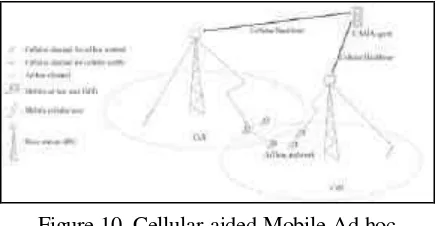
4.5 CAMA: Cellular Aided Mobile Ad hoc Network [15]
In this paper, the proposed network architecture of CAMA has slight different from the previous ones. Figure 10 shows this network architecture. It introduces a new network element called CAMA agents. They are the servers that are in charge of operating CAMA. Each CAMA agent covers a number of cells and knows which mobile terminal (MT) is a registered CAMA user. Their connection to the Home Location Registers (HLRs) gives more user information. By introducing this CAMA agent, network improvement in the aspects of authentication, routing and security can be achieved, because CAMA agent also works as a centralized server for position information, and also authentication, authorization and accounting (AAA) of the ad hoc networks.
Figure 10. Cellular-aided Mobile Ad hoc (CAMA) Network [15]
In the other parts, CAMA can improve the ad hoc network in synchronization, authentication, power saving, radio resource allocation, broadcasting and multicasting, and finding cluster head in clustered ad hoc routing. In the following paragraphs two important aspect of CAMA i.e. routing algorithm and security issue are presented.
4.5.1 Positioning Routing in CAMA
In CAMA, since the CAMA agent may work as a centralized positioning information server. An MT can find its precise geographical position through Global Positioning Satellite (GPS) or location based service of the cellular network itself. The position information is sent to the CAMA agent through the BS. As the result, an initial route from a source to a destination can be determined either by CAMA agents or by MTs
which will be broadcasted by BS to the other MTs. Then CAMA agent initiate centralized routing mechanism to appropriate MTs. The advantages of this mechanism are routing optimizations, security, radio resource allocation and power savings. It also does not need to broadcast the positioning information periodi-cally in downlink direction that bring to reducing of cellular radio bandwidth and MT power consumption.
One weak point of this mechanism is that an MT may have to wait for a long time to get the routing decision from the CAMA agent in the condition there are too many MTs send routing requests simultaneously. The delay can be caused by the uplink transmission collision, uplink request queue, and the downlink reply queue. If the delay is too long, it is possible that a new route has to be determined by the updated position information because of mobility of the users. One idea to avoid lost of position information is by sending HELLO message between two adjacent MTs to make sure they are reachable to each other. This position information can be used by the CAMA agent to know exactly what link exists, and make more accurate routing decisions. However this scheme increases the overhead in both the cellular network and the ad hoc network.
Table 3. Routing Table (Example: for MT A) [15]
Neighboring
Similar to Greedy Proxy Discovery and Routing mechanism of UCAN, with the help of GPS, Multi-Selection Greddy Positioning Routing (MSGPR) of CAMA has better performance. The CAMA agent keeps the position information of each MTs in a table shown by Table 3. The table consists of the IDs and position of neighboring MTs, the distance d, from the MT, and ∆∆d, the change of distance from the MT the last two position updates. When the condition of
closest neighbor nodes is chosen at each step to be continued to the next step. And at the end, there are n = 2 routes are selected, in this case: S
à B à H à G à T and S à C à E à I à T. Some most important criteria are considered to rank these n selected routes, i.e. total delay time and number of hops. At the end only one route is chosen to relay the data packets to the destination MTs.
Figure 11. Multi-Selection Greedy Positioning Routing (MSGPR) with n = 2 [15]
When an MT moves away from its previous position, position update is needed. The new positions of MTs are updated periodically, with a time threshold value for the update period, which brings to a probability of wrong routing decision caused by out-of-date position information. Another threshold value of the distance between the last position of MT and its previous position during last update should be defined. There is some mathematical approximation to define these two thresholds. Special updates should be treated when the radio environment quality of MTs changes significantly, e.g. when an MT experiences a deep fading in a corner or behind a building. These changes can be measured by sending HELLO messages to the other reachable MTs.
4.5.2 Security in CAMA
Security issues in wireless networks design must be considered seriously. In CAMA the security issues is related to the ad hoc network, because cellular network already have own security concerns and solutions. In CAMA, the security of ad hoc network is much easier compared to the pure ad hoc network, because CAMA agent can also act as a central security control point for key distributions, intrusion detections, or broadcasting information through base station when a security violation is detected.
One aspect that should be considered in CAMA system is routing security against the intended falsa positioning information. There are two solutions for this problems i.e. proactive and reactive solution. In the proactive solution, MT will send IDs of their reachable neighboring MTs periodically. This information will be analyzed by CAMA agent to make a judgement whether this MT is sending its true position or not. CAMA agent in the reactive solution will use the reports from MTs which have info of their next hop which is actually does not exist. These MTs will be classified as malicious MTs by CAMA agent and they are excluded from the network. The report is encrypted to ensure the originality and the CAMA agent must have all public key of all the MTs. Some criteria can be used to classified which MTs are always send wrong report about their position and / or routing path,
and which MTs act maliciously only
occasionally. This criteria and mechanism will maintain the CAMA agent to have record of all good MTs.
Another security concern related to the forwarding routing information is to make sure that the routing information from CAMA agent is forwarded to the destination MT consistently. Firstly, the routing information is encrypted by CAMA agent by using secret key of destination MT before it is forwarded. Destination MT will decrypt it by using its public key. Secondly, Watch Dog scheme is used to avoid interruption by intermediate MTs. Thirdly, downlink and uplink data match with Hash code comparison is used to detect such a bad link in in the intermediate links.
of cellular and ad hoc channel jump used by MTs and base station could be difficult to be followed by the attacker.
Introducing of CAMA agent in the cellular multihop network gives some additional improvement in the routing and relay path discovery and maintenance, AAA functions and higher security protection solutions.
5. Conclusions
There are some proposals to implement the Cellular Multihop Network. Each of proposals has different intention of research for the same objectives. The HCMN system gives an overview of complete network architecture. The UCAN system provides more information of algorithm of proxy client and relay path discovery and maintenance. The iCAR system gives more intention to the allocation of fixed ARSs, in this case the number and the location of required ARSs. The PARCelS tries to analyze some situation where mobile clients can also be used as a relay node. The PARCelS also enhances the protocol, and achieves higher performance of getting more load-balance network. At the end the CAMA system introduces a new network element called CAMA agents, to control all mobile nodes in the ad hoc networks. The CAMA agents support not only routing and relay procedure for mobile clients, but also their AAA function and security aspects. In general, all of the proposed architecture fulfilled the objectives. The users who are located in the blank spots of cellular networks can still establish a call connection. Call blocking probability of the networks is decreased. The network can balance the load between hot and cold cells. Cellular and WLAN channel can be used more efficiently. The users of cellular networks can have higher data transfer rata when using the WLAN channel and infrastructure. The users of WLAN networks can be more mobile and still maintain their connection to the networks by relaying the link from one cell to another cell with help of cellular networks. More detail of the value of the experiment and measurement results can be found in the related papers.
The combination of each limited scope of researches should give more powerful network performance and a complete scope of network
and user requirements. Trades off between the benefits and the network complexity and other difficulties have to be considered in the real implementation this cellular multihop network for comercial purposes. Further researches still have to be conducted, and standardization of the networks architecture and functional aspect must be organized to be implemented in the real worlds.
References
[1] G.Aggelou, R.Tafazolli: On the relaying capacity of next-generation GSM cellular networks, in IEEE Personal Communi-cations Magazine, vol.8 no.1, pp, 40-47,
February 2001.
[2] N.Nantavechsanti: Interworking between Ad hoc Network and Supporting Network,
in ACS Seminar, IKR University of Stuttgart, 2003.
[3] W.Fu: Routing Mechanism in Ad hoc
Networks, in ACS Seminar, IKR University of Stuttgart, 2003.
[4] M. Schopp: Lecture Notes of Mobile Communication II, University of Stuttgart & ICM Siemens AG, 2004.
[5] J.Zyren, A.Petrick: IEEE 802.11 Tutorial, 2000.
[6] C.E.Perkins: Mobile Networking Through Mobile IP, in IEEE Internet Computing Magazine, 1998.
[7] T. Buergstein: Security Issues in Commu-nication Systems, in ACS Seminar, IKR University of Stuttgart, 2003.
[8] C.Qiao, H.Wu, O.Tonguz: Integrated cellular and Ad hoc relay systems, in IEEE International Conference on Computer Communication and Network, 2000.
[9] X.Wu, B.Mukherjee, S.-H.G.Chan, B.Bhar-gava: Assuring Communications by Balancing Cell Load in Cellular Network, in IEICE Transaction Communications, Vol.E86-B, No.10, October 2003.
[10] H.Li, M.Lott, W. Zirwas, M.Weckler, E. Schulz: Hierarchical Cellular Multihop Networks, in EPMCC, March 2003.
[11] H.Li, M.Lott, M.Weckerle, W.Zirwas, E.Schulz: Multihop Communications in Future Mobile Networks, in Proceeding PIMRC, September 2002.
Network Architecture, in MobiCom '03, September 2003.
[13] S.De, O.Tonguz, H.Wu, C.Qiao: Integrated Cellular and Ad hoc Relay (iCAR) System: Pushing the Performance Limits of Conven-tional Wireless Networks, in Proc. of the 35th International Conference on System Sciences, 2002.
[14] J.Zhou, Y.R.Yang: PARCelS: Pervasive Ad-hoc Relaying for Cellular Systems,
Department of Computer Science, Yale University, 2003.
![Figure 1. Basic Idea of Cellular MultihopNetworks [1]](https://thumb-ap.123doks.com/thumbv2/123dok/3667342.1468752/2.596.84.306.171.304/figure-basic-idea-cellular-multihopnetworks.webp)
![Figure 2. 3G Networks Architecture(GERAN+UMTS) [4]](https://thumb-ap.123doks.com/thumbv2/123dok/3667342.1468752/3.596.58.279.70.218/figure-g-networks-architecture-geran-umts.webp)
![Figure 3. Integration of Cellular Network andWLAN Ad hoc Network Architecture [4]](https://thumb-ap.123doks.com/thumbv2/123dok/3667342.1468752/5.596.57.279.261.404/figure-integration-cellular-network-andwlan-ad-network-architecture.webp)
![Figure 4. Hierarchical Cellular MultihopNetwork Architecture [10]](https://thumb-ap.123doks.com/thumbv2/123dok/3667342.1468752/6.596.323.537.348.672/figure-hierarchical-cellular-multihopnetwork-architecture.webp)
![Figure 6. Unified Cellular and Ad-hoc Network(UCAN) Architecture [12]](https://thumb-ap.123doks.com/thumbv2/123dok/3667342.1468752/7.596.292.512.211.325/figure-unified-cellular-ad-hoc-network-ucan-architecture.webp)
![Figure 7. (a) Greedy Proxy Discovery andRouting (b) On-demand Discovery andRouting [12]](https://thumb-ap.123doks.com/thumbv2/123dok/3667342.1468752/9.596.57.279.110.486/figure-greedy-proxy-discovery-androuting-demand-discovery-androuting.webp)
![Figure 8. (a) Primary Relaying (b) SecondaryRelaying (c) Cascaded-Secondary Relaying [13]](https://thumb-ap.123doks.com/thumbv2/123dok/3667342.1468752/10.596.320.540.466.561/figure-primary-relaying-b-secondaryrelaying-cascaded-secondary-relaying.webp)
![Figure 9. (a) Simple Relaying approach (b)BetterRelaying Solution [14]](https://thumb-ap.123doks.com/thumbv2/123dok/3667342.1468752/11.596.292.513.440.519/figure-simple-relaying-approach-b-betterrelaying-solution.webp)
![Figure 11. Multi-Selection Greedy PositioningRouting (MSGPR) with n = 2 [15]](https://thumb-ap.123doks.com/thumbv2/123dok/3667342.1468752/14.596.85.304.196.329/figure-multi-selection-greedy-positioningrouting-msgpr-n.webp)
