* Corresponding author.
Email address : [email protected]
POLY(GLYCIDYL METHACRYLATE-DIVINYLBENZENE) MONOLITHIC CAPILLARY
AS A STATIONARY PHASE FOR THE REVERSED-PHASE CHROMATOGRAPHIC
SEPARATION OF PROTEINS
Nurul Hidayat Aprilita
a,*, Rania Bakry
b, Christian W. Huck
band Guenther K. Bonn
ba
Chemistry Department, Faculty of Mathematics and Natural Sciences Gadjah Mada University, Yogyakarta, Indonesia 55281
b
Institute of Analytical Chemistry and Radiochemistry, University of Innsbruck, Innrain 52a, A-6020, Innsbruck, Austria
Received 13 December 2004; Accepted 3 January 2005
ABSTRACT
Capillary column with monolithic stationary phase was prepared from silanized fused-silica capillary of 200 µm I.D. by in situ free radical polymerization of divinylbenzene with glycidy methacrylate in the presence of decanol and tetrahydrofuran as porogens. The hydrodynamic and chromatographic properties of this monolith, such as backpressure at different flow-rate, pore size distribution, van Deemter plot and the effect of varying gradient-rate were investigated. Poly(glycidyl methacrylate-divinylbenzene) monolithic capillary has been used successfully for the reversed-phase chromatographic separation of proteins.
Keywords:monolithic stationary phase, poly(glycidyl methacrylate-divinylbenzene), proteins
INTRODUCTION
A monolithic stationary phase is a continuous unitary porous structure prepared by in situ
polymerization or consolidation inside the column tubing and, if necessary, the surface is functionalized to convert it with the desired chromatographic binding properties [1]. Monolithic stationary phases have attracted considerable attention in liquid chromatography and capillary electrochromatography in recent years due to their simple preparation procedure, unique properties and excellent performance, especially for separation of biopolymers [2].
There were several different monolithic supports described in the literature. They are basically synthesized from different chemical compounds to form styrene [1, 3-10], methacrylates
[11-18], acrylamide [19-26], and silica monoliths
[27-34]. Glycidyl methacrylate-based monoliths were introduced in 1990 [18]. They were polymerized from glycidyl methacrylate (GMA) and ethylene dimethacrylate (EDMA) in the presence of porogens and an initiator. The polymer is chemically and mechanically very stable and contains epoxy groups that can be further modified to prepare the separation units suitable for ion exchange, hydrophobic interaction, reversed-phase, or affinity
separations [16]. Decanol and tetrahydrofuran have been used as macroporogen and microporogen for the fabrication of micropellicular poly(styrene/divinylbenzene) monoliths enables the rapid and highly efficient separation of peptides and proteins by reversed-phase high-performance liquid chromatography (RP-HPLC) [35]. RP-HPLC has grown to become a mature and well-established technique in analysis, structure elucidation, and isolation of peptides and proteins
[36].
This study described the first use of the poly(glycidyl methacrylate-divinylbenzene) (GMD) monolithic capillary for the RP-HPLC of proteins.
EXPERIMENTAL SECTION
Materials
hydrate (DPPH), and 3-(trimethoxysilyl) propyl methacrylate 92% were purchased from Aldrich (Milwaukee, WI, USA). Divinylbenzene and glycidyl methacrylate were distilled before use to remove the inhibitor. The tetrahydrofuran (THF) used as porogen was distilled over sodium metal to remove the inhibitor 2,6-di-tert-butyl-4-methylphenol (BHT). For preparation of all aqueous solutions, high purity water (Epure, Barnstead Co., Newton, MA, USA) was used. The standard proteins were obtained from Sigma (St. Louis, MO, USA).
Instrumentation
The µ-HPLC system consisted of a low-pressure gradient micro pump (model Rheos 2000, Flux Instruments, Karlskoga, Sweden) controlled by a personal computer, a vacuum degasser (model ERC-3215α, Flux Instruments, Karlskoga, Sweden), a micro syringe (model #65, Hamilton Co, Reno, NV, USA), a variable wavelength detector (model Ultimate UV detector, LC Packings, Amsterdam, Netherlands) with a Z-shaped capillary detector cell ULT-UZ-N-10, 3 nL cell, LC Packing), and a PC-based data system (CSW 32, Data Apex Ltd, Prague, Czech Republic). Solutions consisting of 0.1% TFA in water and 0.1% TFA in acetonitrile were used as mobile phase A and B for the gradient elutions, respectively.
Preparation and characterization of the GMD monolithic capillary
Silanization of the fused silica capillary of 200 µm I.D and 3 m in length were prepared according to the published protocol [37]. A solution containing 20% (v/v) of glycidyl methacrylate, 20% (v/v) of divinylbenzene, 5 mg AIBN, 52% (v/v) of decanol, 8% (v/v) THF were first sonificated and purged with helium, then filled into the 20 cm silanized capillary. After both ends of the capillary were sealed, it was placed in the water bath at 70oC for 24 hours. The capillary was positioned horizontally and was continuously rotated along the longitudinal axis to avoid sedimentation of the polymer seed. After polymerization, the capillary was washed with acetonitrile for 1 h at a maximum pressure 25 MPa.
The hydrodynamic property of the column such as specific permeability was assessed by measuring the column backpressure as a function of eluent flow rate with water and methanol. Before measurement the column was flushed with the solvent for 30 minutes. The pore size distribution in dry state was determined by mercury porosimeter. Van Deemter curve was experimentally acquired by injecting a protein standard (myoglobin 0.1 mg/mL) into the
column and eluting it isocratically under the same elution condition at different flow rate.
RESULTS AND DISCUSSION
Characterization of the GMD monolithic capillary
Permeability
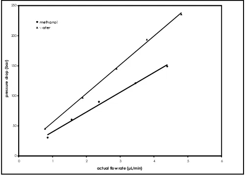
Porous polymeric stationary phase in contact with organic solvents often lacks sufficient mechanical strength and the particles may be deformed under the pressure gradient normally encountered in HPLC column. In order to evaluate the mechanical stability of the column material, the pressure drop across the column was measured upon perfusing it with methanol and water in a wide range of flow rates.
Fig 1 shows the effect of the flow rate on the backpressure in GMD monolithic capillary. A good linear dependence of the column inlet pressure on the flow rate is indicated by a regression factor r ≥ 0.997. This figure also shows that the column is not compressed even at high flow rate. Numerical values for specific permeability of a GMD column were calculated from Dacry’s law [38]. Using the viscosity values of water and methanol i.e. 1.00 10 -3 kg/m.s and methanol is 0.60 10-3 kg/m.s
respectively [39], the permeability B0 of the column is 5.2 10-15 m2 and 4.9 10-15 m2 for water and methanol, respectually.
Figure 1 Graph illustrating plot of pressure drop
versus flow rate of methanol and water. Column GMD, 65 x 0.2 mm; mobile phase, (▲) water, (•) methanol; room temperature
0 50 100 150 200 250
0 1 2 3 4 5 6
actual flow rate (µL/min)
pre
ss
u
re
dro
p
(bar
)
0
linear flow velocity (mm/sec)
pl
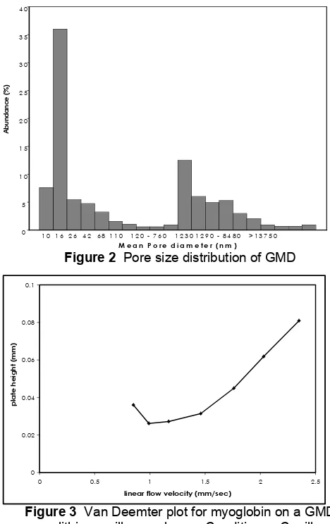
Figure 2 Pore size distribution of GMD
Figure 3 Van Deemter plot for myoglobin on a GMD
monolithic capillary column. Conditions: Capillary; GMD, 72 x 0.2 mm I.D.; mobile phase, 0.1% (v/v) TFA, 70% acetonitrile, flow rate, 1.4-3.9 µL/min, room temperature, detection, UV, 214 nm, sample myoglobin 0.1 mg/mL
Pore size distribution
The utilization of porous monolithic material for HPLC in which a liquid has to flow through the medium requires the flow to be achieved at a reasonably low pressure. Because the pressure depends on the porous properties of the material, the pore size distribution of the monolith should be adjusted to match the application. Typically, the material should contain a sufficient volume of large channel with a diameter about 1 µm and additional diffusive pore smaller than 100 nm.
The result of pore size distribution GMD measured with mercury porosimeter measurements is shown in Fig 2. Obviously, the material contains two sharply divided families of pores. The distributions obtained were bimodal with maximal at 16 and 1230 nm.
Table 1 Height equivalent to a theoretical plate as
a function of flow velocity
Actual flow
The specific surface area was found to be 27.93 m2/g. Polymeric monolith with a low surface area has generally been used for the separation of biopolymer where a large surface are is not required [39].
Van Deemter plot
The performance of columns is often characterized by different forms of so-called van Deemter plot relating the efficiency of the column to the flow rate of the mobile phase. A van Deemter curve was ploted to determine the optimum flow rate for the separation of standard proteins on monolithic column. Myoglobin as a test substance is injected to the column under isocratic elution with eluent of 0.1% (v/v) trifluoroacetic acid in 70% (v/v) acetonitrile (Fig 3).
Height equivalent to a theoretical plate (HETP) was 26.2 µm and the number of theoretical plates (N) was 38,000/m at a linear flow velocity of 0.99 mm/s, which corresponds to actual flow rate of 1.66 µL/min (Table 1). However, it must be considered that for most applications the ultimate column performance is not required if an adequate separation is obtained using higher flow rates (linear velocities).
Separation of proteins on GMD monolithic capillary
A new monolithic capillary column based on poly(glycidyl methacrylate/divinylbenzene) has been prepared by in situ polymerization (Fig 4).
Figure 4 Synthesis of GMD monolithic by free
Time (min)
Figure 5 Separation of proteins on GMD monolithic
capillary column. Conditions: Capillary, monolithic (72 x 0.20 mm I.D.); mobile phase, A = 0.1% aqueous TFA, B = 0.1% TFA in acetonitrile; gradient, 95% - 50% A in 1 minute, 50% -30% A in 5 min, 30% A in 5 min; flow rate, 4 µL/min; detection, UV, 214 nm; room temperature.
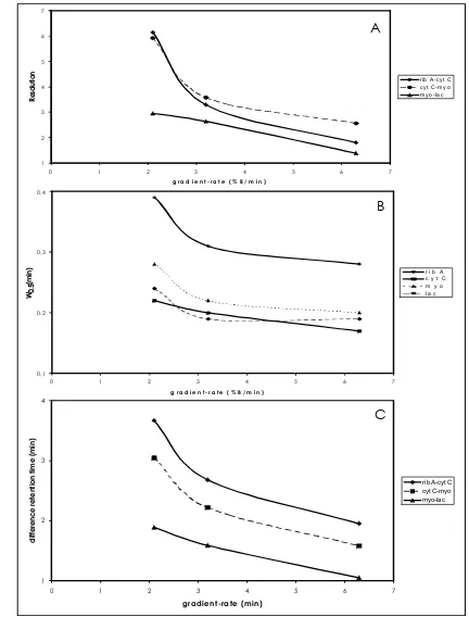
Figure 6 The effect of varying gradient-rate on
separation of proteins using GMD monolith capillary column. Conditions: capillary, 72 x 200 µm I.D.; mobile phase A: 0.1% TFA in water B: 0.1% TFA in acetonitrile, gradient 5-100% B, flow rate 2.65 µL/min, detection UV 214 nm, room temperature, injection volume 2 µL (1=ribonuclease A, 2=cytochrome C, 3=myoglobin and 4=α-lactalbumin).
Table 2 Retention time (tR) and peak widths at half
height (W0.5) of standard proteins separated on GMD monolithic capillary
Figure 7 Graphical representation of effect of
varying gradient-rate on sensitivity of peak detection. Column and conditions are the same as described in figure 6.
Figure 8 Graphical representation of effect of
varying gradient-rate on protein resolution (A), peak width at half-height (B) and difference in retention times (C).
A good separation of proteins by reversed-phase chromatography on GMD monolithic capillary is illustrated in Fig 5. The peak widths at half height were between 4.2 – 9 seconds (Table 2) by applying a gradient in 11 minutes.
6, at constant flow rate there is a decrease in protein peak height as the gradient-rate is decreased from 6.3% B/min to 2.1% B/min. The effect of varying gradient-rate at constant flow rate on the peak height of proteins is illustrated graphically in Fig 7. Peak height increases with increasing gradient-rate, so increasing the gradient-rate will increase the sensitivity of protein detection. The effect of varying gradient-rate on the resolution is shown in Fig 8A; the effect on the peak width at half-height is shown in Fig 8B; the effect on ∆t is shown in Fig 8C. Gradient rate variations have a profound impact on protein separations. From Fig 8, there is a general improvement in protein resolution with decreasing gradient-rate, despite the concomitant increases the peak width at half-height and retention time.
CONCLUSION
We have demonstrated utilization of a new monolithic capillary based on poly(glycidyl methacrylate-divinylbenzene) for reversed-phase chromatography of proteins. The prepared GMA monolithic capillary exhibits mechanical stability and good chromatographic properties at optimized condition.
ACKNOWLEDGEMENTS
Technology Grant Southeast Asia scholarship from The Austrian Federal Ministry for Education, Science and Culture to Nurul Hidayat Aprilita is gratefully acknowledged.
9. Premstaller, A., Oberacher, H., and Huber, C.G., 2000, Anal. Chem., 72, 4386.
10. Huber, C.G., Premstaller, A., Xiao, W., Oberacher, H., Bonn, G.K., and Oefner, P.J., 2001, J. Biochem. Biophys. Methods., 47, 5.
11. Xie, S., Allington, R.W., Svec, F., and Fréchet, J.M.J., 1999, J. Chromatogr. A., 865, 169. 12. Svec, F., and Fréchet, J. M. J., 1995, J.
Chromatogr. A., 702, 89.
13. Sykora, D., Svec, F., and Fréchet, J.M.J., 1999, J. Chromatogr. A., 852, 297.
14. Peters, E.C., Petro, M., Svec, F., Fréchet, J.M.J., 1997, Anal. Chem., 69, 3646.
15. Luo, Q., Zou, H., Zhang, Q., Xiao, X., Guo, Z., Kong, L., and Mao, X., 2001, J. Chromatogr. A., 926, 255.
16. Podgornik, A., Barut, M., Strancar, A., Josic, D., and Koloini, T., 2000, Anal. Chem., 72, 5693.
17. Zhang, S., Zhang, J., and Horvárt, C., 2001, J.
Chromatogr. A., 914, 189.
18. Tennikova, T.B., Belenkii, B.G., and Svec, F., 1990, J. Liq. Chromatogr., 13, 63.
19. Hjertén, S., Liao, J., and Zhang, R., 1989, J.
Chromatogr., 473, 273.
20. Liao, J., Zhang, R., and Hjertén, S., 1991, J.
Chromatogr., 586, 21.
21. Zeng, C., Liao, J., Nakazato, K., and Hjertén, S., 1996, J. Chromatogr. A., 753, 227. 28. Minakuchi, H., Nakanishi, K., Soga, N.,
Ishizuka, N., and Tanaka, N., 1996, Anal.
Chem., 68, 3498.
29. Cabrera, K., Wieland, G., Lubda, D., Nakanishi, K., Soga, N., Minakuchi, H., and Unger, K.K., 1998, Trend Anal. Chem. 17, 50. 30. Tanaka, N., Kobayashi, H., Ishizuka, N.,
Minakuchi, H., Nakanishi, K., Hosoya, K., and Ikegami, T., 2002, J. Chromatogr. A., 965, 35. 31. Cabrera, K., Lubda, D., Eggenweiler, H.
Minakuchi, H., and Nakanishi, K., 2000, J. High
Resol. Chromatogr., 23, 93.
32. Tanaka, N., Nagayama, H. Kobayashi, H., Ikegami, T., Hosoya, K., Ishizuka, N., Minakuchi, H., Nakanishi, K. Cabrera, K., and Lubda, D., 2000, J. High Resol. Chromatogr.,
23, 111.
33. Motokawa, M., Kobayashi, H., Ishizuka, N., Minakuchi, H., Nakanishi, K., Jinnai, H., Hosoya, K., Ikegami, T., and Tanaka, N., 2002,
34. Lubda, D., Cabrera, K., Kraas, W., Schaefer, C., and Cunningham, D., 2001, LCGC., 19, 1186. 35. Premstaller, A., Oberacher, H., Walcher, W.,
Timperio, A.M., Zolla, L., Chervet, J., Cavusoglu, N., Dorsselaer, A., and Huber, C.G., 2001, Anal.
Chem., 73, 2390.
36. Esser, U. and Unger, K.K., 1991, High-Performance Liquid Chromatography.
Separation, Analysis and Conformation, edt C.T.
Mant, R.S. Hodges, CRC Press, Florida, p. 273.
37. Huang, X. and Horvárt, C., 1997, J.
Chromatogr. A., 788, 155.
38. Maa, Y.F. and Horvárt, C., 1988, J.
Chromatogr. 445, 71.