ARIS Design Platform: Getting Started with BPM Rob Davis and Eric Brabänder
978-1-84628-612-4
Business Process Modelling with ARIS: A Practical Guide Rob Davis
Rob Davis
ARIS Design Platform
ISBN: 978-1-84800-110-7 e-ISBN: 978-1-84800-111-4 DOI 10.1007/978-1-84800-111-4
British Library Cataloguing in Publication Data
A catalogue record for this book is available from the British Library
© Springer-Verlag London Limited 2008
Apart from any fair dealing for the purposes of research or private study, or criticism or review, as permitted under the Copyright, Designs and Patents Act 1988, this publication may only be reproduced, stored or transmitted, in any form or by any means, with the prior permission in writing of the publishers, or in the case of reprographic reproduction in accordance with the terms of licences issued by the Copyright Licensing Agency. Enquiries concerning reproduction outside those terms should be sent to the publishers.
The use of registered names, trademarks, etc. in this publication does not imply, even in the absence of a specific statement, that such names are exempt from the relevant laws and regulations and therefore free for general use.
The publisher makes no representation, express or implied, with regard to the accuracy of the information contained in this book and cannot accept any legal responsibility or liability for any errors or omissions that may be made.
Printed on acid-free paper
9 8 7 6 5 4 3 2 1
Springer Science+Business Media springer.com
Library of Congress Control Number: 2008926119 British Telecommunications plc
DEDICATION
For Sally,
Acknowledgements
I would like to thank all my colleagues at BT, many of whose ideas have contrib-uted to the store of knowledge I have built up and which has enabled me to write this book. In particular to Ordelia Sansford for reviewing some of the chapters.
Also thanks to the staff at IDS Scheer in Germany and the UK who have pro-vided much help and assistance. In particular Andrea Albrecht and Britta Hilt for arranging for people to review parts of the book and especially to reviewers in-cluding: Christina Reinshagen, Philipp Lahmé and Hans Maas. Further thanks to Britta Hilt for providing previews of ARIS 7.1.
Thanks also to Eric Brabänder for working with me on the previous book. He didn’t join me on this book and I missed his support and our late night voicecon-ferences.
I would like thank Springer-Verlag for the opportunity to publish the book. In particular Beverley Ford for her continued enthusiasm for ARIS books; to Cath-erine Brett for all her help and support, and to Frank Ganz for his assistance on the book layout.
I would also like to thank IDS Sheer AG for permission to reproduce screen shots of the ARIS Platform and to use figures and text from ARIS promotional and technical documentation.
Finally I would like to thank Sally for putting up with me for a second year of book writing.
Contents
Acknowledgements ...vii
Chapter 1 Introduction ... 1
1.1 Introduction to the ARIS Platform ... 1
1.2 What’s in this Book ... 3
1.3 How to Use this Book ... 5
1.4 References... 6
1.5 Icons Used in This Book... 6
1.6 Conventions Used in this Book... 7
Chapter 2 Before You Start Modelling... 9
2.1 Objectives for Modelling ... 9
2.1.1 Why Are You Modelling?... 10
2.1.2 What Are You Modelling? ... 10
2.1.3 Who Are You Modelling?... 12
2.1.4 When Are You Modelling? ... 13
2.2 Modelling Requirements... 14
2.3 Key Principles... 16
Chapter 3 Process Capture and Modelling ... 17
3.1 Introduction... 17
3.2 Modelling in Teams ... 17
3.3 Modelling Standards ... 18
3.4 Process Modelling... 19
3.4.1 Model Structure... 19
3.4.2 Libraries and Processes ... 20
3.4.3 What Models to Use... 21
3.5 Process Capture... 22
3.5.1 Process Capture Using ARIS ... 22
3.5.2 A Two-Stage Approach to Process Capture ... 23
3.6 Verification and Validation... 26
3.7 Roles and Responsibilities ... 27
3.7.8 Process Architect... 31
3.7.9 Corporate Process Architect... 31
3.7.10 ARIS Technical Consultant... 32
3.7.11 ARIS Database Administrator... 32
3.7.12 ARIS Server Administrator... 33
3.7.13 ARIS Configuration Administrator ... 33
3.7.14 IT System Administrator... 34
3.7.15 ARIS Model Publisher ... 34
3.7.16 ARIS Trainer... 35
Chapter 4 The Matrix Editor ... 37
4.1 The Matrix Editor ... 37
4.2 Creating a Matrix ... 38
4.2.1 Creating an Empty Matrix... 38
4.2.2 Creating a Matrix from Existing Objects ... 39
4.2.3 Opening a Matrix ... 39
4.3 Saving a Matrix... 39
4.4 Deleting a Matrix ... 40
4.5 Matrix Window... 40
4.5.1 Navigation Bar ... 41
4.5.2 Matrix Tabs ... 41
4.5.3 Contents Bar... 42
4.6 Selecting Object Types ... 42
4.7 Inserting Objects into a Matrix ... 44
4.7.1 Inserting New Objects... 46
4.7.2 Inserting Existing Objects ... 47
4.8 Selecting Connection Types ... 48
4.9 Selecting Connection Settings ... 50
4.10 Viewing Connections... 52
4.10.1 Connection Display... 52
4.10.2 Connection Properties, Attributes and Occurrences... 53
4.10.3 Changing the Display Order... 54
4.10.4 Hiding Rows and Columns ... 56
4.10.5 Zoom ... 56
4.10.6 Row and Column Titles ... 57
4.10.7 Connection Abbreviations... 58
4.11 Editing Connections... 58
4.11.1 Creating a Connection... 59
4.11.2 Deleting a Connection... 61
4.11.3 Interpreting Cell Displays ... 61
4.12 Exporting to Excel ... 62
4.13 Printing a Matrix... 63
Contents xi
Chapter 5 Find and Query ... 65
5.1 Introduction to Find and Queries ... 65
5.2 Standard Find ... 65
5.2.1 Opening the Find Dialog Box ... 65
5.2.2 Selecting the Item Type... 66
5.2.3 Search Based on Item Name ... 67
5.2.4 Searching with Wildcards ... 68
5.2.5 Search with Time and Date Qualifier... 69
5.2.6 Search Based on Attribute Value ... 69
5.2.7 Viewing Search Results ... 70
5.2.8 Using Search Results... 70
5.3 Find Objects with Identical Names ... 71
5.4 Creating Queries ... 73
5.4.1 Introduction to Queries... 73
5.4.2 Opening the Query Wizard... 73
5.4.3 Select Creation Mode ... 74
5.4.4 Create Query ... 75
5.4.5 Restrict Input Types ... 76
5.4.6 Restrict Result Types ... 77
5.4.7 Select Relationship... 78
5.4.8 Select Attributes ... 82
5.4.9 Confirm Input... 82
5.4.10 Editing Queries... 83
5.4.11 Running a Query ... 83
5.4.12 Running an Attribute-Based Query ... 86
5.4.13 Example Queries ... 87
5.5 Nesting Queries... 90
5.5.1 Creating Nested Queries... 91
5.5.2 Example Nested Queries ... 92
5.6 Distributing Queries... 94
6.2.1 Generating Models from Other Models ... 96
6.2.2 Options for Generating Models from Models ... 98
6.2.3 Generating Models from Objects ... 102
6.2.4 Options for Generating Models from Objects ... 103
6.2.5 Managing Generated Models ... 105
6.2.6 Model Generation from Shortcuts ... 106
6.3 Generating Vertical Views of the Hierarchy... 107
6.3.1 The Function Hierarchy and the Function Tree... 107
6.3.2 Generating a Function Hierarchy ... 109
6.4.1 Model Generation of the End-to-End Process... 112
6.4.2 Benefits of Generating an End-to-End Process Model... 114
6.4.3 Handling Process Variants with Model Generation ... 114
6.5 Linking EPCs for Model Generation ... 114
6.5.1 Linking Models Using Events... 115
6.5.2 Linking Using the Process Interface Object... 116
6.6 Generating Models Spanning Levels of the Hierarchy ... 118
6.6.1 The Linking Diagram... 118
Chapter 7 Modelling in Rows and Columns ... 121
7.1 Row and Column Models ... 121
7.1.1 Modelling in Swim-lanes ... 121
7.1.2 When to Use a Swim-lane Model ... 122
7.1.3 Horizontal or Vertical?... 122
7.1.4 Row/Column EPCs in a Model Hierarchy ... 123
7.2 The Row and Column EPC... 123
7.2.1 The Layout of a Row/Column EPC ... 123
7.2.2 The Implicit Relationship... 125
7.2.3 Multiple Relationships in Row/Column EPCs ... 125
7.2.4 Modelling Multiple Systems ... 127
7.2.5 Modelling Other Resources in Row/Column EPCs ... 128
7.2.6 Changing Implicit Relationships... 128
7.2.7 Row and Column Properties ... 130
7.2.8 Automatic Layout of Row and Column EPCs ... 131
7.2.9 Model Generation and Row/Column EPCs... 132
7.3 Specialised Row/Column Models... 135
7.3.1 The Process Chain Diagram... 135
7.3.2 E-Business Scenario Diagram... 137
7.3.3 Column EPC for Modelling Systems Interfaces ... 137
Chapter 8 Modelling Process Variants... 141
8.1 Avoiding Stovepipes... 141
8.2 Modelling Variety... 141
8.3 Creating Multiple EPC Assignments ... 143
8.4 A Model Hierarchy with Variant Sub-Processes ... 144
8.4.1 Creating Variant Relationships Between Sub-Processes ... 145
8.4.2 Creating Sub-Processes as Variant Copies... 146
8.4.3 Viewing Variant Relationships ... 147
8.4.4 Creating Variants of Variants... 147
8.4.5 Modelling the Product/Process Hierarchy... 148
8.4.6 Modelling the Product/Process Matrix... 149
8.5 Generating a Product-Specific End-to-End Process... 151
8.5.1 Model Generation from Shortcut Groups... 152
Contents xiii
Chapter 9 ARIS Evaluations ... 155
9.1 Evaluations... 155
9.2 Creating and Managing Evaluation Scripts... 159
9.2.1 The Evaluation Folder... 159
9.3.2 Modifying Report Settings ... 162
9.3.3 Running Reports... 165
9.4 Semantic Checks... 168
9.4.1 Creating Semantic Checks ... 168
9.4.2 Creating New Rule Types ... 169
9.4.3 Modifying Rule Type Settings ... 169
9.4.4 Creating New Rules ... 172
9.4.5 Modifying Rules... 172
9.4.6 Creating New Profiles ... 172
9.4.7 Modifying Existing Profiles ... 173
9.4.8 Running Semantic Checks ... 175
9.5 Macros ... 177
9.5.1 Creating Macros ... 177
9.5.2 Modifying Macro Settings ... 178
9.5.3 Assign Macros to the Menu and Toolbar ... 180
9.5.4 Running Macros ... 181
9.5.5 Command Line Macros ... 182
9.6 Transformations ... 182
9.6.1 Creating a Transformation... 182
9.6.2 Running a Transformation ... 186
Chapter 10 Database Administration ... 187
10.1 The Need for Administration ... 187
10.2 Administrative Accounts and Privileges ... 187
10.2.1 Passwords, Accounts and Privileges ... 187
10.2.2 Function Privileges... 190
10.2.3 System Account ... 191
10.2.4 Administration Passwords... 191
10.3 Server Administration ... 193
10.3.2 Server Configuration... 194
10.4 Database Management ... 195
10.4.1 Create Database... 195
10.4.2 Open and Close Database... 195
10.4.3 Delete Database... 196
10.4.4 Rename Database ... 196
10.4.5 Copy and Paste Database ... 196
10.4.6 Reorganise Database ... 197
10.4.7 Backup Database... 198
10.4.8 Restore ... 199
10.4.9 Statistics ... 199
10.4.10 Export and Import ... 200
10.4.11 Merge ... 201
10.6.4 Model and Object Management ... 218
10.6.5 Consolidating Objects ... 220
10.7 Merging Databases ... 226
10.7.1 Introduction to Merge ... 226
10.7.2 The GUID ... 227
10.7.3 The Merge Concept... 227
10.7.4 Making a Merge ... 229
10.8 Administration Reports... 234
10.9 The ARIS Admintool... 234
Chapter 11 User Administration ... 237
11.1 Introduction to User Administration ... 237
11.1.1 The Need for User Administration... 237
11.1.2 System Account ... 238
11.1.3 Strategy for User Management ... 238
11.1.4 Undertaking User Administration ... 240
11.2 Create New User Account ... 240
11.2.1 Create User... 241
11.2.2 User Group Association ... 242
11.2.3 Identifier... 243
11.2.4 Function Privileges ... 245
Contents xv
11.2.6 Confirm Input... 246
11.2.7 User Attributes ... 247
11.2.8 Editing User Accounts ... 247
11.2.9 User Account Properties... 248
11.2.10 Logining in as a User ... 249
11.3 Create New User Group... 250
11.3.1 Create User Group... 250
11.3.2 User Association ... 251
11.3.3 User Group Attributes ... 251
11.3.4 User Group Properties... 252
11.4 Merging Users... 252
11.5 Database Access Control ... 253
11.5.1 Introduction to Access Control... 253
11.5.2 User and User Group Access Privileges... 254
11.5.3 Group Access Privileges ... 257
11.6 User Administration Reports ... 259
11.7 Lightweight Directory Access Protocol (LDAP) ... 259
Chapter 12 Configuring the ARIS Method... 261
12.1 ARIS Configuration ... 261
12.1.1 Method ... 262
12.1.2 Conventions... 263
12.1.3 Using ARIS Configuration... 263
12.2 The Principles of Configuring ARIS... 264
12.2.1 Introduction ... 264
12.2.2 The ARIS Method ... 265
12.2.3 The ARIS House ... 266
12.2.4 Why Not Just Use the Entire Method? ... 267
12.2.5 Things to Consider ... 268
12.2.6 Choosing Models, Objects and Relationships ... 270
12.2.7 A Reference Model ... 271
12.3 Configuring the Method... 273
12.3.1 Introduction to Configuring the Method ... 273
12.3.2 Renaming Attribute Type Groups ... 273
12.3.3 Renaming Attributes ... 275
12.3.4 Allocating Attributes to Attribute Type Groups... 276
12.3.5 Renaming Attribute Units ... 277
12.3.6 Renaming User Attributes ... 278
12.3.7 Renaming Connection Types ... 279
12.3.8 Renaming Model Types ... 281
12.3.9 Creating Derived Model Types ... 281
12.3.10 Renaming Object Types ... 283
12.3.11 Renaming Symbols ... 283
12.3.12 Creating User-defined Symbols ... 284
Chapter 13 The Symbol Editor ... 287
13.1 Introduction... 287
13.2 The Drawing Window ... 288
13.2.1 Scaling the Symbol View... 288
13.2.2 The Overview Window ... 289
13.2.3 Window Properties... 290
13.3 The Graphic Symbols Bar... 290
13.3.1 Adding ARIS Symbols to the Graphic Symbols Bar ... 291
13.3.2 Removing a Symbol from the Graphic Symbols Bar ... 291
13.4 Creating a Symbol ... 292
13.4.1 Using Existing Symbols... 292
13.4.2 Inserting Shapes ... 292
13.4.3 Inserting the Name Attribute... 293
13.4.4 Inserting Text ... 294
13.4.5 Importing a Graphic File... 294
13.4.6 Setting the Display Order... 294
13.4.7 Aligning Shapes ... 295
13.4.8 Saving and Resizing a Symbol... 295
13.4.9 Exporting a Symbol ... 296
13.4.10 Undo and Redo... 296
13.6 Using the New Symbol ... 302
Chapter 14 Method Filters and Evaluation Filters ... 303
14.1 The Importance of Method Filters ... 303
14.1.1 Evaluation Filters ... 303
14.1.2 Languages ... 304
14.2 Creating and Editing Filters ... 304
14.2.1 Create Filter ... 304
14.2.2 Edit Filter ... 305
14.2.3 Select Creation Mode... 305
14.2.4 Create Filter ... 306
14.2.5 Select Model Types... 308
14.2.6 Select Object Types ... 308
14.2.7 Select Connection Types... 308
14.2.8 Select Symbols... 310
14.2.9 Assign Connection Types ... 311
14.2.10 Select Assignments ... 313
14.2.11 Select Model Attributes... 314
Contents xvii
14.2.13 Select Connection Attributes... 316
14.2.14 Select Attribute Order ... 316
14.2.15 Select Symbol Order ... 317
14.3 Creating a Filter from a Database ... 318
14.3.1 Creating Reference Models ... 319
14.3.2 Attribute Selections ... 322
14.3.3 Symbol and Attribute Order ... 324
14.3.4 Creating the Filter from the Reference Models ... 325
14.4 Merging Filters... 325
14.5 Applying Filters ... 326
14.6 Exporting and Importing Filters... 327
14.6.1 Exporting a Filter ... 327
14.6.2 Importing a Filter ... 327
14.6.3 Method Configuration ... 328
Chapter 15 Defining and Using Templates ... 331
15.1 Introduction to Templates ... 331
15.2 Fonts and Languages... 332
15.3 Creating a New Template ... 333
15.3.1 Create Template ... 334
15.3.2 Select Symbols ... 336
15.3.3 Select Symbol Appearance... 336
15.3.4 Place Symbol Attributes... 338
15.3.5 Select Connection Types ... 341
15.3.6 Select Connection Appearance... 342
15.3.7 Place Connection Attributes... 344
15.3.8 Select Model Background ... 346
15.4 Editing Templates ... 346
15.5 Exporting and Importing Templates ... 347
15.5.1 Exporting a Template ... 347
15.5.2 Importing a Template ... 347
15.6 Applying Templates... 347
15.6.1 Applying a Template to a Model... 348
15.6.2 Applying a Template to Objects and Connections ... 349
15.6.3 Setting the Current Model Template ... 349
15.6.4 Setting the Default Model Template ... 350
15.6.5 Effect of Templates ... 352
Chapter 16 Administration Reports ... 355
16.1 Introduction... 355
16.2 Copying Users and User Groups Report... 356
16.3 Database Information Report... 357
16.4 Replace Font Formats Report ... 359
16.5 Replace Object Types Report ... 359
16.6 Replace Symbol Types Report... 364
16.7 Consolidate Objects Report ... 366
16.8 Output Group Information Report ... 368
16.9 Replace Text Attributes Report ... 369
16.10 Transfer Groups and Users Report... 372
16.11 Format Models Report ... 373
Chapter 17 Model Verification ... 375
17.1 Why Verify? ... 375
17.2 What Should be Verified?... 375
17.2.1 Checks on Individual Models... 376
17.2.2 Checks on the Database ... 376
17.2.3 Checks on Multiple Models ... 377
17.2.4 Checks on Model Structure and Linking... 377
17.3 Tools for Verification ... 377
17.3.1 Animation ... 377
17.3.2 Compare... 377
17.3.3 Find Objects with Identical Names ... 379
17.3.4 Consolidate ... 379
17.4.1 Checks on Individual Models... 384
17.4.2 Checks Across the Database ... 387
17.4.3 Checks on Multiple Models ... 390
17.4.4 Checks on Model Structure and Linking... 392
Appendix A ARIS Admintool Commands ... 393
Glossary... 397
Chapter 1
Introduction
This chapter gives an overview of the ARIS Platform and the ARIS products. The structure of the book is described with advice for different reader groups.
1.1
Introduction to the ARIS Platform
The ARIS products are aligned to the Business Process Management (BPM) lifecycle and offered in an integrated software solution grouped into four ARIS Platforms:
x The Strategy Platform, x The Design Platform,
x The Implementation Platform, x The Controlling Platform.
The system architecture of the ARIS Platform allows globally distributed organi-sations to set up common scenarios for designing, analysing, and optimising proc-esses, IT, and software architectures.
Web-based products such as ARIS Business Optimizer, ARIS Business Archi-tect, ARIS Business Designer, and ARIS UML Designer can access a centrally managed ARIS Business Server from anywhere in the world via a three-tier archi-tecture. These products are designed to use utilise low bandwidth connections (e.g. dial-up, ISDN, etc.). Web-based clients can be started directly from within a Web browser or, alternatively, they can be installed as a desktop application manually or by automated software distribution. In both cases, any necessary client updates can be set up and controlled centrally to facilitate the rollout process.
The integrated software solution of the ARIS Platform has two key characteristics:
x Central data repository,
x Common language and semantics.
All the ARIS products have been developed by IDS Scheer without the need to integrate any external software not based on the central repository concept. Inte-gration also means everything you model and describe using the ARIS Platform products is based on common language and semantics that can be understand by all users. The semantics of describing process models and enterprise information is based on the underlying concept which gave ARIS its name.
“ARIS – Architecture of Integrated Information Systems”
The ARIS Platform offers a high level of system scalability and availability. For instance, the majority of modellers can use ARIS Business Designer, while a smaller number of expert users can provide central administrative functions (e.g. management of access privileges, available reports, conventions/filters, etc.) using ARIS Business Architect. It is these expert users that this book is intended for.
What’s in this Book 3
1.2
What’s in this Book
After the success of my first book on ARIS Toolset:
“Business Process Modelling with ARIS – A Practical Guide”,
I teamed up with Eric Bräbender from IDS Scheer to work together on a new book:
“ARIS Design Platform: Getting Started with BPM”.
In this book we provided a practical ‘how-to’ guide to using the ARIS Design Platform and gave an introduction to starting out on Business Process Manage-ment (BPM) based on ARIS modelling. We covered the basic principles of using ARIS Business Architect and ARIS Business Designer to design processes and in-troduced many of the key concepts, models and objects including:
x How to establish BPM with ARIS,
x Background to modelling and the ARIS Method, x Basic instructions for using ARIS Business Designer, x Selected information on using ARIS Business Architect, x How to structure a business process architecture, x How to set and use standards,
x Hints and tips on ARIS Business Architect and ARIS Business Designer. Following on from that, this latest book complements the ARIS Design Plat-form, updating some material from the original ARIS Toolset book while adding new material on topics such as the Matrix Editor, Database Administration and Configuring the ARIS Method. In particular, it covers in detail the following top-ics aimed at more expert users:
x Issues to consider before starting a modelling project, x Advanced modelling concepts and tools,
x Database administration and configuration.
There are several target groups for this book:
x People familiar with ARIS Business Architect who wish to use some of the more advanced modelling concepts and tools,
x People who need to manage ARIS modelling projects,
x People who need to Administer ARIS databases for projects and organisations,
x People who need to define and configure the ARIS Method and modelling conventions for their organisation,
x People who wish to use the ARIS Design Platform for the development of organisation-wide BPM systems,
x People with experience and knowledge of ARIS Toolset or ARIS Easy Design who want to migrate to the web-based ARIS products.
For all these groups the book provides a practical ‘how-to’ guide to what are complex topics, however plenty of space is given to providing lots of hints and tips regarding the practical use of ARIS Business Architect.
I have been using ARIS in British Telecommunications plc for more than ten years and was responsible for implementing ARIS in BT. I introduced ARIS, both to process modellers familiar with other tools, and to people with little experience of tools or modelling. My colleagues and I had to work out what standards to de-fine, how to publish them, how to review them and how to overcome natural resis-tance to change. Although most users had been trained, what they needed above all was an easy-to-understand guide to how to apply the tool for modelling their business.
I have tried to mix detailed advice about how to operate key aspects of ARIS Business Architect, along with guidance on how to go about process modelling us-ing ARIS in your organisation and wherever possible I have stuck to the ARIS Method. My approach won’t suite everyone, but if you use it as a starting point you can develop your own style and techniques as you progress.
Inevitably, this is my pragmatic approach to modelling your business in ARIS based on my experience. It is not intended to replace the published information on the ARIS Method or the ARIS product range, the ARIS help files, or any training you may receive from IDS Scheer.
I have described and illustrated ARIS Business Architect version 7.02 (as of December 2007). There may be small differences with later versions of ARIS, but nevertheless the basic principles of modelling with ARIS Business Architect should remain the same. Where I have indicated ‘bugs’ or ‘limitations’ with the current release, these have be reported to IDS Scheer and may well have been fixed by the time you read this book.
How to Use this Book 5
1.3
How to Use this Book
Unlike the previous book, which was intended be read through from beginning to end, this book is more of a reference manual of the more advanced ARIS Business Architect facilities. You should be able to read a chapter on any topic that interests you in isolation. However there is a great deal of interaction between some topics (i.e. Database Administration and User Administration) so you may find yourself having to refer to other chapters to get a full understanding of what you need.
I would not recommend anyone to try to read the book in one go. Using ARIS successfully is based on practice and experience. It is best to read a few chapters and try out the techniques described, moving on to more complex material as you become more familiar and confident.
Depending on your interest you may wish to concentrate on chapters in the fol-lowing areas:
x Issues to consider before starting a modelling project: x Chapter 2 – Before You Start Modelling,
x Chapter 3 – Process Capture and Modelling. x Advanced modelling concepts and tools:
x Chapter 4 – The Matrix Editor, x Chapter 5 – Find and Query, x Chapter 6 – Model Generation,
x Chapter 7 – Modelling in Rows and Columns, x Chapter 8 – Modelling Process Variants, x Chapter 9 – ARIS Evaluations.
x Database administration and configuration: x Chapter 10 – Database Administration, x Chapter 11 – User Administration,
x Chapter 12 – Configuring the ARIS Method, x Chapter 13 – The Symbol Editor,
x Chapter 14 – Method Filters and Evaluation Filters, x Chapter 15 – Defining and Using Templates, x Chapter 16 – Administration Reports, x Chapter 17 – Model Verification,
1.4 References
Davis R (2001) Business Process Modelling with ARIS: A Practical Guide, Springer-Verlag, London.
Davis R, Brabänder E (2007) ARIS Design Platform: Getting Started with BPM, Springer-Verlag, London.
1.5
Icons Used in This Book
To draw your intention to hints and tips, and to make you aware of possible prob-lems, I have used the following icons:
Warning – this is a warning symbol. These warnings should not be ignored, otherwise dire effects will be experienced which will influence your work with ARIS. You have been warned so there is no excuse if you go ahead and do so. I take no responsibility for any subsequent loss or damage.
Hint – hints will help you to work more efficiently with ARIS Business Architect. Following these hints will speed up your daily work or, at the very least, will allow you to impress your colleagues!
Expert Tip – these tips will give you examples of more detailed, and sometimes more complex, facilities you may wish to try once you have mastered the basics.
Conventions Used in this Book 7
1.6
Conventions Used in this Book
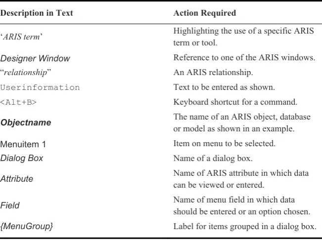
I have described the use of the keyboard and the mouse to operate ARIS Business Architect in plain English wherever I can. I have used the English spelling of words like ‘reorganise’ in the main body of the text, but show the actual spelling and capitalisation used in ARIS Business Architect (e.g. US English – “reorgan-ize”) in command strings. In order to save space when listing commands, I have used the conventions shown in Table 1.1 and Table 1.2 as shortcuts for complex commands.
Table 1.1 Text Formatting Conventions Used in this Book
Description in Text Action Required
‘ARIS term’ Highlighting the use of a specific ARIS
term or tool.
Designer Window Reference to one of the ARIS windows.
“relationship” An ARIS relationship.
Userinformation Text to be entered as shown.
<Alt+B> Keyboard shortcut for a command.
Objectname The name of an ARIS object, database or model as shown in an example.
Menuitem 1 Item on menu to be selected.
Dialog Box Name of a dialog box.
Attribute Name of ARIS attribute in which data
can be viewed or entered.
Field Name of menu field in which data
should be entered or an option chosen.
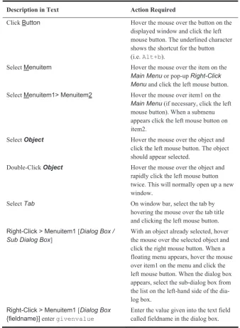
Table 1.2 Command Descriptions Used in this Book
Description in Text Action Required
Click Button Hover the mouse over the button on the
displayed window and click the left mouse button. The underlined character shows the shortcut for the button (i.e. Alt+b).
Select Menuitem Hover the mouse over the item on the
Main Menu or pop-up Right-Click Menu and click the left mouse button. Select Menuitem1> Menuitem2 Hover the mouse over item1 on the
Main Menu (if necessary, click the left mouse button). When a submenu appears click the left mouse button on item2.
Select Object Hover the mouse over the object and
click the left mouse button. The object should appear selected.
Double-Click Object Hover the mouse over the object and
rapidly click the left mouse button twice. This will normally open up a new window.
Select Tab On window bar, select the tab by
hovering the mouse over the tab title and clicking the left mouse button.
Right-Click > Menuitem1 [Dialog Box / Sub Dialog Box]
With an object already selected, hover the mouse over the selected object and click the right mouse button. When a floating menu appears, hover the mouse over item1 on the menu and click the left mouse button. When the dialog box appears, select the sub-dialog box from the list on the left-hand side of the dia-log box.
Right-Click > Menuitem1 [Dialog Box
{fieldname}] enter givenvalue
Chapter 2
Before You Start Modelling
This chapter looks at the issues you need to consider before starting to model with ARIS. Of particular importance is the need to define your objectives and viewpoint.
2.1
Objectives for Modelling
Before starting any modelling project it is important to be clear about why you are modelling. It is surprising how many people start modelling without any idea of what the model is for, who will use it, what type of information is required and in what format the output will be needed. Remember, a process model is not a rep-lica of the real world; it is merely a representation – a viewpoint. It is essential the viewpoint is tailored for its intended use and the people who will view it. Differ-ent viewpoints may be needed for differDiffer-ent purposes. One of the key strengths of ARIS is its ability to produce different viewpoints based on common underlying data. Some views can be produced automatically (e.g. using Model Generation), while others are constructed manually.
The objectives of your modelling may change during the life of the project. This may be due to changing requirements, discovery of new opportunities or planned enhancement of the model. Do not assume that models created to meet one set of objectives will be suitable for other objectives. Sometimes models de-veloped with one viewpoint may even conflict with models produced for other purposes. For instance, a high-level abstract model of the business may over-simplify interactions between business units and appear to conflict with what ac-tually goes on. Ideally, we would like to create a set of hierarchical models which provide increasing levels of detail about our business, but sometimes we must be aware that a high-level abstract model will not ‘cleanly’ decompose into more de-tailed models because its viewpoint is very different.
It is strongly recommend you explicitly write down your objectives, agree them with your stakeholders and document them in the database (you can use the Objectives Diagram). Below is a list of some of the key questions you should ask yourself:
2.1.1 Why Are You Modelling?
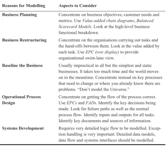
What is the main purpose of the modelling work? Table 2.1 shows some possible reasons.
Table 2.1 Why Are You Modelling?
Reasons for Modelling Aspects to Consider
Business Planning Concentrate on business objectives, customer needs and metrics. Use Value-added chain diagrams, Balanced Scorecard Models. Look at the high-level business functional breakdown.
Business Restructuring Concentrate on the organisations carrying out tasks and the hand-offs between them. Look at the value added by each task. Use EPC (row display) to provide
organisational swim-lane view.
Baseline the Business Usually impractical in all but the simplest and static businesses. It takes too much time and the world moves on in the meantime. Concentrate instead on key processes that need to change or where you already know there are problems. “Don’t model the Universe.”
Operational Process Design
Concentrate on getting the flow of the process correct. Use EPCs and FADs. Identify the key decisions being made. Look for failure paths as well as the normal process flow. Identify inputs and outputs for all tasks. Identify key documents and sources of information. Systems Development Requires very detailed logic flow to be modelled.
Excep-tion handling is very important. Detailed data models, data flow and systems interfaces should be modelled.
2.1.2 What Are You Modelling?
You may be modelling a process, an organisation, the data or the many other as-pects of an organisation that ARIS can represent. Normally you will be modelling several of these. However you should decide the main viewpoint from which you will be modelling. Typical viewpoints are shown in Table 2.2.
Objectives for Modelling 11
Table 2.2 What Are You Modelling?
Modelling Viewpoint Approach
Follow a business entity Possibly the easiest approach to take. Select a key busi-ness item (e.g. a customer order) and follow it through the process. See what actions are performed on it, who handles it and where it ends up. This is also useful for testing other model viewpoints.
Model the business Modelling what the whole business does is one of the hardest approaches. It can normally only be done at high levels of abstraction and it is often difficult to identify the triggers and outcomes.
Model a business function The most common approach is to model a particular busi-ness function (e.g. order-handling, fault-reporting, etc). This will normally involve many different organisational units. Modelling organisational hand-offs will be essen-tial. Can lead to very ‘company oriented’ models that don’t focus on the customer.
Model a business process The most useful approach (but not often done) is to model the end-to-end processes a business performs. Par-ticularly valuable when done from a customer perspec-tive. Better than the business function approach as it helps ensure the whole process fits together to deliver a good customer experience. Helps identify failure modes. Model an organisation Another common approach is to model what an
organisa-tion does. This may not necessarily be the most useful approach. Organisations change over time and the range of tasks an organisation performs may have evolved his-torically.
Model an organisational unit
This model just focuses on what a single unit does. The model shows the interfaces with other units, but doesn’t worry about how they accomplish their tasks. Provides a very focused model, but can over-simplify what is going on. It may also encourage an out-of-sight, out-of-mind approach, which doesn’t spot gaps and failure points in the end-to-end process.
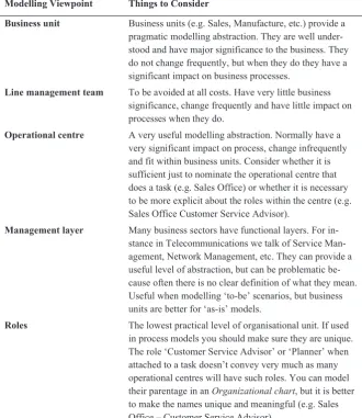
2.1.3 Who Are You Modelling?
Related to the choice of viewpoint, you also need to think about what level of or-ganisation you are considering, as shown in Table 2.3.
Table 2.3 Who Are You Modelling?
Modelling Viewpoint Things to Consider
Business unit Business units (e.g. Sales, Manufacture, etc.) provide a pragmatic modelling abstraction. They are well under-stood and have major significance to the business. They do not change frequently, but when they do they have a significant impact on business processes.
Line management team To be avoided at all costs. Have very little business significance, change frequently and have little impact on processes when they do.
Operational centre A very useful modelling abstraction. Normally have a very significant impact on process, change infrequently and fit within business units. Consider whether it is sufficient just to nominate the operational centre that does a task (e.g. Sales Office) or whether it is necessary to be more explicit about the roles within the centre (e.g. Sales Office Customer Service Advisor).
Management layer Many business sectors have functional layers. For in-stance in Telecommunications we talk of Service Man-agement, Network ManMan-agement, etc. They can provide a useful level of abstraction, but can be problematic be-cause often there is no clear definition of what they mean. Useful when modelling ‘to-be’ scenarios, but business units are better for ‘as-is’ models.
Objectives for Modelling 13
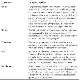
2.1.4 When Are You Modelling?
It is important to consider both the time-frame within which you are modelling and also the granularity of time that is important to you (Table 2.4).
Table 2.4 When Are You Modelling?
Timeframe Things to Consider
‘as-is’ The process as it is now. But be careful to define what ‘now’ means. Does it mean what should be happening now, as documented now or as actually operated now? If you know the documented process is not being followed and a ‘work-around’ is being used, you need to decide which you are going to model. If changes are being made while you are capturing the process, will you include them or freeze the model at a certain point in time? ‘to-be’ How far in the future are you considering? Are you
start-ing from scratch with a new business model or re-engineering what you already have? How radical can you be? What constraints have you got?
Time-scale Complex processes can sometimes complete within seconds, while simple processes can often last for weeks. What time-frame is important to your model?
Delays Are potential delays in the process important to you? Populating Function attributes with process times may not make delays explicit to people viewing the model. Consider explicitly modelling delays as additional steps in the process if you want to draw attention to them. Simulation Simulation can be used to analyse process delays and
op-timise performance. A very powerful tool, but requires good quality models and good quality data. Models must conform to certain rules. Consider seeking advice from specialist simulation experts.
2.2 Modelling
Requirements
We will have already captured some requirements by considering our modelling objectives and thinking through the viewpoints we wish to take. However, we need to think further about how our models are to be used. For instance:
x Who are our customers for the models?
x What are they expecting the models to tell them? x Do they want to see the models or just the results? x How are they going to view the models?
x How much time will they spend viewing the models? x How widely will models be promulgated?
x Will different groups of people require different views? x Will they use ARIS themselves?
x Will they want printed reports?
x Is this a one-off exercise or will the models be maintained? x How will models be validated?
x Will the models be used for system, workflow or software design? x Will the models be used for analysis or BPR?
x Is simulation required?
These are important questions and you may find it more difficult than you ex-pect to find the answers; it is quite common for people to ask for models to be built without any clear idea of what they are going to do with them. You may go through the objectives-setting exercise described above and quite clearly define what models are required, but still be no wiser about what the customers plan to do with them. This is often because people are tempted to believe that, simply by having a process (or business) model, this will solve all their problems and the business will automatically operate as described in the model.
Of course it is not fair to blame the customer; the onus is on process modellers to work with customers to ‘tease’ out exactly what the models are for and to sug-gest innovative ways in which the models can be used. However, don’t take at face value what the customer initially asks for. A good example is the use of ARIS Reports to generate printed documents. Business teams often start by stating a key requirement is that ARIS should automatically generate printed documents in the same format as they currently use. When asked why, typically they reply:
x Senior managers only want documents,
x Operational people wouldn’t understand the ARIS models, x ARIS models are too big,
Modelling Requirements 15
Of course, in reality senior managers never read the documents and operational people are much happier with the flowchart approach of EPCs. It seems strange people should object to printed EPCs that run to several pages, but seem quite happy with documents of 100 pages or more! While there is some argument for having information in document form when ‘off-line’, in practice there is rarely a need to create reports that exactly replicate existing documents.
The most successful teams are usually those are innovative in their use of ARIS and change the way they work. Typically, they publish their models on the Intra-net and use Microsoft NetMeeting (or similar approaches) to validate ARIS mod-els in their electronic form through virtual workshops. Of course you cannot achieve this overnight. Most teams have to gradually move to these new ways of working and you need to consider the business culture in which you are operating. You will need to demonstrate what can be done with ARIS and give people time to realise how it may benefit them.
Some requirements can have significant impact on how you go about model-ling. For instance, using ARIS Simulation places certain constraints on the struc-ture and format of your models, and requires particular data (e.g. task processing times) to be captured. It is important to be clear about these requirements at the start, as having to go back to capture and model missing data can be costly and time-consuming. You also need to be clear about what sort of analysis you may wish to perform. For instance, if you wish to be able to ask questions such as “Tell me all the Functions executed by this Organizational unit?”, then you must model the Organizational unit that executes every Function. There is no value in popu-lating part of the model with Organizational units and not the rest, because the analysis would be inaccurate. This is particularly important when you have several people working on process design or capture. If they don’t all follow the same rules, your model will be inconsistent.
2.3 Key
Principles
All the while you are developing your models, either at the conceptual level or during detailed design, keep in mind some key principles:
x Stick to the ARIS Method (well mostly), x Don’t model the universe,
x Know when you have done enough,
x Keep it simple – clever models often confuse, x Define standards and stick to them,
x Don’t re-invent the wheel; re-use wherever you can,
x If it looks sensible it probably is sensible – if it looks silly it definitely is silly. The ‘keep it simple’ rule is of particular importance. The more you learn about ARIS, the more intellectually stimulating it becomes to find really clever ways to model various aspects of the business. Sometimes this may produce ‘clean and elegant’ models that provide real clarity and insight. More frequently, however, it creates highly complex models that no one can understand. Always ask yourself: “If I had to hand over all my modelling work to another ARIS user, would that person be able to easily carry on using the same approach?” If you can’t answer “yes” to this question, then you need to review the way you are working. The closer you stick to the ARIS Method and agreed standards, the easier it will be to achieve this.
References
Chapter 3
Process Capture and Modelling
This chapter describes approaches for process capture and modelling. It discusses some of the issues that must be considered, the models you might use and the roles and responsibilities involved.
3.1 Introduction
In the last chapter we looked at the issues to consider before starting modelling, particularly the need to define your modelling objectives. Once you are clear about your objectives you can start detailed capture and design. The actual way you go about this will very much depend on the nature of the project, what infor-mation is already to hand and how many people are involved in the modelling ac-tivity. Some key issues to think about are discussed below.
3.2 Modelling
in
Teams
If you have teams of modellers working on a project, it is much easier if they all share the same ARIS database located on a networked server. You can appoint people to the roles described in Section 3.7; in particular appointing a Model Li-brarian (see Section 3.7.5), to create a library of resource objects and insisting that modellers use them. If modellers need new objects, not currently in the library, ei-ther they must ask the Librarian to create a new object, or they create it them-selves and then submit it to the Librarian for approval. When using an ARIS server, the Group Access Privileges for library objects and groups can be con-trolled so that some groups of people can create and change objects, while others can use them, but not change them.
If you have teams of modellers working on the project who are not sharing the same database it is still possible to create a central library and distribute it to indi-vidual users who can use the ARISMerge facility to add the library into their own database. Using the same technique they can also send potential library objects back to the Librarian. Although this is technically straightforward, it requires a great deal more project management and administration to ensure success.
These issues can only be resolved manually although, as mentioned above, ARIS does have tools to help you. See Chapter 10 for more detail on database admini-stration including merging databases and consolidating objects.
Modelling in teams is a complex issue, but as a general rule, it works better if there is significant and continual interaction between the modellers and adminis-trators as the project progresses. It is a recipe for disaster to allow everyone to work by themselves for most of the project and then try to bring everything to-gether at the end. Even if server-based working is not feasible, it is still essential to create a master database. You should partition each modeller’s work into small well-defined segments and provide them with a copy of the library from the mas-ter database and any models with which they need to inmas-teract. When they have fin-ished their (small) element of the work, merge it into the master database and re-solve any conflicts and issues. Then allocate them a new piece of work and provide them with an update of the relevant parts of the master database.
Working this way places a lot of responsibility and work on the Database Ad-ministrator and the Model Librarian, but it does ensure that issues are resolved as the project progresses rather than being left to the end. It also provides the Data-base Administrator and Project Manager with an evolving view of how the model and the project are progressing.
3.3 Modelling
Standards
Before undertaking any serious modelling you must agree and set standards. This is important, even if you are the only modeller, but it is absolutely essential if you have a team of people modelling. In ARIS there is no single way of doing things and hence, if you start a number of people modelling processes, they will all choose to use different models and different ways of using them. We can apply corporate modelling conventions and standards through:
x Structure:
Process Modelling 19
For a detailed discussion of implementing process standards see “Ch16 - Stan-dardised Modelling with ARIS” in Davis and Brabänder 2007.
Not only do you need to agree on the major standards topics, but even trivial tasks like grid settings, use of colour, etc. are worth agreeing in advance. It gives a much more professional appearance if all the models produced by the team have the same look and feel. The use of ARIS Method Filters and Conventions is ex-tremely valuable in establishing corporate modelling conventions. We will look at these in more detail in later chapters of this book.
3.4 Process
Modelling
3.4.1 Model Structure
As we saw above, an important aspect of creating a standardised approach to process modelling, especially when modelling in teams, is the structure of your process models. Deciding upon and creating a model structure raises some key questions:
x Should you create you structure first and then create your models? x Should you create all your models and then try and work out a structure? x Should you work ‘top-down’ or ‘bottom-up’?
In an ideal world you would create your structure using a top-down approach. Then you would create models containing increasing levels of detail that fit into the structure. This would be very similar to the way software is designed (at least in theory). In practice it is very difficult to do this. You may start with high-level models which show relatively simple interfaces between key business functions, but it is only when you start to model in more detail you discover the real complexity of the interactions between business functions. This means you may have to re-visit your high-level models to adjust their structure. For more information on structuring ARIS models see “Chapter 13 - Modelling your Business Structure” in Davis and Brabänder 2007.
The same situation occurs in software design, but it is much more prevalent in process design. Why is this? The reason is mainly due to the optimisation of de-sign for performance. In software engineering, systems are broken down into a large number of well-understood ‘atomic’ tasks or components with simple and well-defined interfaces. Vast numbers of these components are combined to form a working system. Despite the vast number of components, today’s high-performance systems can execute each component very quickly providing a high level of performance.
repetitive operations. Hence processes tend to have fewer tasks (components) and fewer interfaces, but those interfaces tend to be more complex and more highly in-terconnected. Moreover, whereas in software systems it is easy to re-use compo-nents whenever they are needed, it is much harder to re-use process tasks. A task in one part of the process may superficially look the same as another, but is often done by different people in a different location using different systems. Re-engineering the process to make the tasks truly common is by no means easy.
So we find developing process models in a truly hierarchical manner is not that straightforward. The big danger is having created a structure; people may spend a lot of time trying to force the process models to fit the structure.
It seems natural to conceive a hierarchical structure and then segment each layer of the hierarchy into a number of separate models, perhaps representing functional areas. If you really can achieve this, that’s excellent, go right ahead. But most people can’t visualise the structure they need sufficiently well at the out-set to be able to do this. In practice, you have to proceed using a more trial-and-error approach.
The best approach is to create an initial structure to provide a rough framework to build on. Then decide on the level of detail you need to model to achieve your main objectives. You may have to go down to more detail later to achieve the re-mainder of your objectives, but you will usually find there is a level of detail at which it seems natural to work. Start creating your model in an EPC. Don’t worry initially about trying to segment the model into a number of separate EPCs. Just create one big model and see how it turns out. As you progress you should start to see the structure of the process emerging, and you can decide how to break the large model up into smaller segments. You can then revise your original rough structure and start to fit new models into it. Don’t spend too long fiddling about with high-level structures. Once you start detailed modelling, you will probably find you have to change it all.
Try and be consistent about the level of detail at which you model. This can also be hard to achieve. There are no hard and fast rules. Sometimes you will want to mix trivial, but highly significant, tasks at the same level as complex tasks that may have several layers of decomposition. Just use your common sense. Ask yourself: “Does it look right?”
3.4.2 Libraries and Processes
Process Modelling 21
for instance, the Find > Objects with Identical Name and Consolidate facilities de-scribed in Chapter 10.
A lot will depend on the degree of detail to which you model systems, organisa-tion and data. If you have a complex structure of these objects that you need to use in your EPCs, it is worth modelling the structure first to ensure it is well under-stood. In practice, a mixture of the two is required, but the more up-front work that can be done, the better.
3.4.3 What Models to Use
Deciding what models to use can be somewhat of a black art. The EPC and FAD are the obvious models to use, typically supported by Organizational charts, En-tity Relationship Models and Application system type diagrams.
In more complex business models the choice is not so straightforward. Some models are more useful than others, some objects are only available in certain types of model and the relationships between objects differ between models. A degree of experimentation is often necessary to decide which objects and models best suit your needs before you start modelling in earnest.
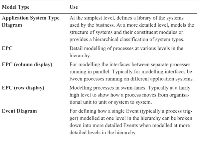
Even in basic process design you have the choice of whether to create organisa-tional charts, whether to use swim-lane models, and so on. Table 3.1 summarises the ARIS model types which are most useful and what they should be used for. For more information on ARIS models and objects see Davis and Brabänder 2007.
Table 3.1 Important ARIS Models
Model Type Use
Application System Type Diagram
At the simplest level, defines a library of the systems used by the business. At a more detailed level, models the structure of systems and their constituent modules or provides a hierarchical classification of system types.
EPC Detail modelling of processes at various levels in the
hierarchy.
EPC (column display) For modelling the interfaces between separate processes running in parallel. Typically for modelling interfaces be-tween processes running on different application systems.
EPC (row display) Modelling processes in swim-lanes. Typically at a fairly
high level to show how a process moves from organisa-tional unit to unit or system to system.
Event Diagram For defining how a single Event (typically a process
Model Type Use
Function Allocation Diagram (FAD)
For defining the relationship between a Function and the resources needed to execute it and the data it transforms.
Function Tree Models the functional structure of a business in a
hierarchical way.
Entity Attribute Diagram Models the decomposition of data entities showing the attributes they are comprised of.
Entity Relationship Model A formal model of the data entities used by the business and the relationships between them. Typically used for representing data used by databases or other systems.
Knowledge Map Models the knowledge held by different business units.
Knowledge Structure Diagram
Hierarchical definition of the knowledge held by the business.
Objective Diagram Models a hierarchy of business objectives along with
their critical success factors, and the Functions and Products that support achievement of those objectives.
Office Process A form of the EPC model using pictorial symbols aimed
at presenting process flows to people less familiar with standard ARIS models.
Organisation Chart A hierarchical model of the business organisation.
Product/Service Tree Models the hierarchy of the products and services produced by the business, the Functions that deliver them and the Business Objectives their production achieves.
Technical Terms Model Models the hierarchical and relational structure of information used by the business.
Value-added Chain Diagram
Models a hierarchy of high-level Functions that add value to the business along with the Organisational Units that have a role in those Functions.
3.5 Process
Capture
3.5.1 Process Capture Using ARIS
Process Capture 23
The rigour of using the ARIS Event-driven process chain approach creates real-istic and consistent process models and so, wherever possible, you should always make use of ARIS for process capture. The exercise of having to think about what Event and Function objects actually represent helps you identify the real process flow, the actual outcomes and the failure modes. Extending this by adding re-source allocations focuses attention on the systems, the people, the data and other resources involved in the process. If you can use these techniques when talking to the process users and experts it will help to articulate what is really happening.
Of course you must be well skilled in the use of ARIS and feel confident about using it in front of other people before attempting to do this. Some people feel ei-ther this is too hard or that showing people ARIS is a distraction from the informa-tion gathering task. While this may certainly be true in some circumstances, the advantages to be gained in the rapid development of more realistic models can far outweigh the disadvantages.
It is worth making sure beforehand that the process users are aware you intend to work this way. A good approach is to meet them on an earlier occasion and give them a brief demonstration of ARIS. They will then have an appreciation of what you are trying to do and will not be distracted by the tool on the process capture day. They will also have the opportunity to gather any appropriate supporting in-formation beforehand.
The alternative is to collect the necessary information by taking notes and by obtaining documents and other information. However, as soon as you start to use ARIS to create the model, you will find its rigour will cause you to ask questions you can’t answer from the information you have gathered. You will then have to go back to the process users and ask additional questions. This is time-consuming, prone to error and does not promote a professional image.
A compromise is to manually collect information and produce a rough ARIS model. Then make a return visit to the process user and ‘walk-through’ the ARIS model with them. If you explain beforehand this is how you intend to work, it re-inforces a professional image and makes them feel continually involved in the process capture exercise.
3.5.2 A Two-Stage Approach to Process Capture
The best method for using ARIS for process capture is to use a two-stage ap-proach. In the first stage, walk through the process with the user and capture the basic process flow. Keep in mind your modelling objectives and remain focused on ‘what you are modelling’ (i.e. follow the progress of a specific order). Pay par-ticular attention to decision points and branches in the process.
Once you have a first draft of the process flow, walk through the process again and start to identify the key resources used by the process (e.g. data, systems, documents, etc) and who carries out the process (e.g. departments, roles, etc).
additional step preceding the current step that acquired the necessary information. So this second phase not only collects additional information about the process, it also verifies the process flow is correct.
Our captured process model will now represent: x The structure of the business process,
x The resources needed to execute it, x The environment in which it will be used.
It is also important to ensure that when you have finished, you present the re-sults back to the people who provided the information, even if they are not the customers for the work. Not only does this ensure good relations are maintained (you may want to go back to them during future work), but they may also directly benefit from the findings of your modelling and analysis.
The two-stage approach to process capture using ARIS is summarised in Table 3.2. If you can achieve all of this, you will have a pretty good first draft model. It will be quite hard work and you should not try and do too much in one session. It is useful to collect any documents and forms used in the process so that you can produce data models of these later if required.
You will need to decide to what level of detail you model the failure modes of the process. If a failure significantly changes the process flow, it should be mod-elled. If a failure stops the process and creates an ‘exception’ that is handled by separate manual intervention, it may be sufficient to note this in a remark and model the exception-handling routine as a separate process.
Process Capture 25
Table 3.2 A Process Capture Approach
Step Things to Consider
Stage 1 – Capture the Process Flow
1 Work through a segment of the process, task by task. 2 Identify the trigger and outcome Events for each Function:
– ensure the triggers are necessary and sufficient, – check the effect of multiple triggers,
– ensure all the outcomes are identified, – ensure failure modes are identified. 3 Identify key decision points in the process:
– make sure there is a Function representing the decision, – identify the correct Rule (usually an XOR).
4 Identify branches and links to other processes: – identify if branches are actually simultaneous,
– identify if links to other processes return to the modelled process, – model ‘out-of-scope’ processes where appropriate.
Stage 2 – Capture Process Resources and Details
5 Identify the systems, organisation and resource supporting each Function: – ask how the process is handed-off from one organisation to another, – ask how the process is handed-off from one system to another, – if hand-offs are important to the process, model them explicitly. 6 Identify the data input and output for each Function:
– identify information carriers,
– identify where data inputs are created (should they be earlier outputs?), – identify where data outputs are used,
– ask for copies of the documents or forms the data objects represent, – ask for data definitions or data models.
7 Ask how the people executing the Function know what to do: – identify key roles and responsibilities,
– identify special skills,
– identify documented knowledge or procedures,
– ask for copies of relevant documents (link electronic versions to the model). 8 Define relevant attributes:
– add task descriptions,
– identify and enter processing times (process, set-up, wait), – enter other supporting information.
9 Review all the organisational and system objects: – check if the relationships between them are clear,
3.6
Verification and Validation
Producing models is not enough in itself; it is essential to ensure they are consis-tent, correct and fit-for-purpose. Verification and validation are the techniques used to ensure this:
x Verification – ensures the models meet the customer’s specification, they are consistent and conform to specified standards,
x Validation – ensures the models meet the customer’s requirements and are fit-for-purpose.
The difference between verification and validation is subtle and often confused. However, we can think of them as ‘inward looking’ and ‘outward looking’.
Verification is ‘inward looking’. It is all about checking you have done what you said you would do; that you have modelled what was asked of you, you have used the ARIS Method correctly, your models are consistent and they reflect the information you were given. This is the responsibility of the modelling team. If you find you can’t deliver what was asked or the information you have been given is inconsistent and incorrect, then it is the team’s responsibility to raise these is-sues with the customers. You must also ensure any isis-sues are resolved, so that at the end of the project you can demonstrate to the customer you have met their specification. Ensuring you meet the specification, and being able to demonstrate that you have met it, is the function of your quality management system. We will discuss techniques for verifying that models are logically correct, consistent and conforms to the ARIS Method in Chapter 17.
Roles and Responsibilities 27
3.7
Roles and Responsibilities
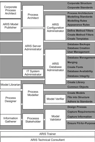
While undertaking process capture and modelling you will require, and interact with, a number of different roles and responsibilities. Some of these will be within the process team and people will need to be assigned to them, other roles will be external to the team. Some roles will be formal roles that people will be aware they have, others will be unofficial roles people play during the process capture or design. People may have multiple roles and if you are a lone modeller, you will have to do many of them yourself! Typical roles include:
x Process Stakeholder, x Information Gatherer, x Process Designer, x Process Modeller, x Model Librarian, x Model Verifier, x Model Validator, x Process Architect,
x Corporate Process Architect, x ARIS Technical Consultant, x ARIS Database Administrator, x ARIS Server Administrator, x ARIS Configuration Administrator, x IT System Administrator,
x ARIS Model Publisher, x ARIS Trainer.
Fig. 3.1 Roles and Responsibilities
Process Architect Corporate
Process Architect
IT System Administrator
Model Librarian ARIS Model
Publisher
Model Verifier
Information Gatherer
Model Validator Processs
Stakeholder
ARIS Technical Consultant ARIS Trainer Process
Designer
Process Modeller ARIS Server Administrator
ARIS Configuration Administrator