Make everything as simple as possible, but not simpler. —Albert Einstein (1879–1955)
A computer can be described constructively, by laying out its hardware platform and explaining how it is built from low-level chips. A computer can also be described abstractly, by specifying and demonstrating its machine language capabilities. And indeed, it is convenient to get acquainted with a new computer system by first seeing some low-level programs written in its machine language. This helps us understand not only how to program the computer to do useful things, but also why its hard-ware was designed in a certain way. With that in mind, this chapter focuses on low-level programming in machine language. This sets the stage for chapter 5, where we complete the construction of a general-purpose computer designed to run machine language programs. This computer will be constructed from the chip set built in chapters 1–3.
A machine language is an agreed-upon formalism, designed to code low-level programs as series of machine instructions. Using these instructions, the programmer can command the processor to perform arithmetic and logic operations, fetch and store values from and to the memory, move values from one register to another, test Boolean conditions, and so on. As opposed to high-level languages, whose basic design goals are generality and power of expression, the goal of machine language’s design is direct execution in, and total control of, a given hardware platform. Of course, generality, power, and elegance are still desired, but only to the extent that they support the basic requirement of direct execution in hardware.
be construed as both a programming tool and an integral part of the hardware plat-form. In fact, just as we say that the machine language is designed to exploit a given hardware platform, we can say that the hardware platform is designed to fetch, in-terpret, and execute instructions written in the given machine language.
The chapter begins with a general introduction to machine language program-ming. Next, we give a detailed specification of the Hack machine language, covering both its binary and its symbolic assembly versions. The project that ends the chapter engages you in writing a couple of machine language programs. This project offers a hands-on appreciation of low-level programming and prepares you for building the computer itself in the next chapter.
Although most people will never write programs directly in machine language, the study of low-level programming is a prerequisite to a complete understanding of computer architectures. Also, it is rather fascinating to realize how the most sophis-ticated software systems are, at bottom, long series of elementary instructions, each specifying a very simple and primitive operation on the underlying hardware. As usual, this understanding is best achieved constructively, by writing some low-level code and running it directly on the hardware platform.
4.1
Background
This chapter is language-oriented. Therefore, we can abstract away most of the details of the underlying hardware platform, deferring its description to the next chapter. Indeed, to give a general description of machine languages, it is sufficient to focus on three main abstractions only: a processor, a memory, and a set of registers.
4.1.1 Machines
A machine languagecan be viewed as an agreed-upon formalism, designed to ma-nipulate amemoryusing aprocessorand a set ofregisters.
address. In what follows we will refer to such individual words using the equivalent notation Memory[address], RAM[address], or M[address] for brevity.
Processor The processor, normally called Central Processing Unit or CPU, is a device capable of performing a fixed set of elementary operations. These typically include arithmetic and logic operations, memory access operations, and control (also called branching) operations. The operands of these operations are binary values that come from registers and selected memory locations. Likewise, the results of the operations (the processor’s output) can be stored either in registers or in selected memory locations.
Registers Memory access is a relatively slow operation, requiring long instruc-tion formats (an address may require 32 bits). For this reason, most processors are equipped with several registers, each capable of holding a single value. Located in the processor’s immediate proximity, the registers serve as a high-speed local memory, allowing the processor to manipulate data and instructions quickly. This setting enables the programmer to minimize the use of memory access commands, thus speeding up the program’s execution.
4.1.2 Languages
A machine language program is a series of coded instructions. For example, a typical instruction in a 16-bit computer may be 1010001100011001. In order to figure out what this instruction means, we have to know the rules of the game, namely, the in-struction set of the underlying hardware platform. For example, the language may be such that each instruction consists of four 4-bit fields: The left-most field codes a CPU operation, and the remaining three fields represent the operation’s operands. Thus the previous command may code the operation set R3 to R1þR9, depending of course on the hardware specification and the machine language syntax.
Taking this symbolic abstraction one step further, we can allow ourselves not only toreadsymbolic notation, but to actuallywriteprograms using symbolic com-mands rather than binary instructions. Next, we can use a text processing program to parse the symbolic commands into their underlying fields (mnemonics and oper-ands), translate each field into its equivalent binary representation, and assemble the resulting codes into binary machine instructions. The symbolic notation is called as-sembly language, or simplyassembly, and the program that translates from assembly to binary is calledassembler.
Since different computers vary in terms of CPU operations, number and type of registers, and assembly syntax rules, there is a Tower of Babel of machine languages, each with its own obscure syntax. Yet irrespective of this variety, all machine lan-guages support similar sets of generic commands, which we now describe.
4.1.3 Commands
Arithmetic and Logic Operations Every computer is required to perform basic arithmetic operations like addition and subtraction as well as basic Boolean oper-ations like bit-wise negation, bit shifting, and so forth. Here are some examples, written in typical machine language syntax:
ADD R2,R1,R3 // R2<---R1+R3 where R1,R2,R3 are registers
ADD R2,R1,foo // R2<---R1+foo where foo stands for the // value of the memory location pointed // at by the user-defined label foo.
AND R1,R1,R2 // R1<---bit wise And of R1 and R2
Memory Access Memory access commands fall into two categories. First, as we have just seen, arithmetic and logical commands are allowed to operate not only on registers, but also on selected memory locations. Second, all computers feature ex-plicitload andstorecommands, designed to move data between registers and mem-ory. These memory access commands may use several types of addressing modes— ways of specifying the address of the required memory word. As usual, different computers offer different possibilities and different notations, but the following three memory access modes are almost always supported:
LOAD R1,67 // R1<---Memory[67]
// Or, assuming that bar refers to memory address 67:
LOAD R1,bar // R1<---Memory[67]
m Immediate addressing This form of addressing is used to load constants— namely, load values that appear in the instruction code: Instead of treating the nu-meric field that appears in the instruction as an address, we simply load the value of the field itself into the register, as follows:
LOADI R1,67 // R1<---67
m Indirect addressing In this addressing mode the address of the required memory location is not hard-coded into the instruction; instead, the instruction specifies a memory location that holds the required address. This addressing mode is used to handle pointers. For example, consider the high-level command x=foo[j], where foois an array variable andxandjare integer variables. What is the machine lan-guage equivalent of this command? Well, when the array foo is declared and ini-tialized in the high-level program, the compiler allocates a memory segment to hold the array data and makes the symbolfoorefer to thebase addressof that segment.
Now, when the compiler later encounters references to array cells likefoo[j], it translates them as follows. First, note that the jth array entry should be physically located in a memory location that is at a displacement j from the array’s base ad-dress (assuming, for simplicity, that each array element uses a single word). Hence the address corresponding to the expressionfoo[j]can be easily calculated by add-ing the value ofjto the value offoo. Thus in the C programming language, for ex-ample, a command likex=foo[j]can be also expressed asx=*(foo+j), where the notation ‘‘*n’’ stands for ‘‘the value ofMemory[n]’’. When translated into machine language, such commands typically generate the following code (depending on the assembly language syntax):
// Translation of x=foo[j] or x=*(foo+j): ADD R1,foo,j // R1<---foo+j
LOAD* R2,R1 // R2<---Memory[R1] STR R2,x // x<---R2
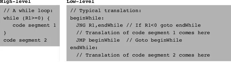
backward to the beginning of a loop),conditional execution(if a Boolean condition is false, jump forward to the location after the ‘‘if-then’’ clause), andsubroutine calling ( jump to the first command of some other code segment). In order to support these programming constructs, every machine language features the means to jump to selected locations in the program, both conditionally and unconditionally. In assem-bly languages, locations in the program can also be given symbolic names, using some syntax for specifying labels. Figure 4.1 illustrates a typical example.
Unconditional jump commands like JMP beginWhile specify only the address of the target location. Conditional jump commands like JNG R1,endWhile must also specify a Boolean condition, expressed in some way. In some languages the condition is an explicit part of the command, while in others it is a by-product of executing a previous command.
This ends our informal introduction to machine languages and the generic oper-ations that they normally support. The next section gives a formal description of one specific machine language—the native code of the computer that we will build in chapter 5.
4.2
Hack Machine Language Specification
4.2.1 Overview
The Hack computer is a von Neumann platform. It is a 16-bit machine, consisting of a CPU, two separate memory modules serving as instruction memory and data memory, and two memory-mapped I/O devices: a screen and a keyboard.
High-level Low-level
JNG R1,endWhile // If R1<0 goto endWhile // Translation of code segment 1 comes here JMP beginWhile // Goto beginWhile
endWhile:
// Translation of code segment 2 comes here
Memory Address Spaces The Hack programmer is aware of two distinct address spaces: an instruction memoryand a data memory. Both memories are 16-bit wide and have a 15-bit address space, meaning that the maximum addressable size of each memory is 32K 16-bit words.
The CPU can only execute programs that reside in the instruction memory. The instruction memory is a read-only device, and programs are loaded into it using some exogenous means. For example, the instruction memory can be implemented in a ROM chip that is pre-burned with the required program. Loading a new program is done by replacing the entire ROM chip, similar to replacing a cartridge in a game console. In order to simulate this operation, hardware simulators of the Hack plat-form must provide a means to load the instruction memory from a text file contain-ing a machine language program.
Registers The Hack programmer is aware of two 16-bit registers called D and A. These registers can be manipulated explicitly by arithmetic and logical instructions like A=D-1 or D=!A (where ‘‘!’’ means a 16-bit Not operation). While D is used solely to store data values, A doubles as both a data register and an address register. That is to say, depending on the instruction context, the contents of A can be inter-preted either as a data value, or as an address in the data memory, or as an address in the instruction memory, as we now explain.
First, the A register can be used to facilitate direct access to the data memory (which, from now on, will be often referred to as ‘‘memory’’). Since Hack instruc-tions are 16-bit wide, and since addresses are specified using 15 bits, it is impossible to pack both an operation code and an address in one instruction. Thus, the syntax of the Hack language mandates that memory access instructions operate on an implicit memory location labeled ‘‘M’’, for example, D=M+1. In order to resolve this address, the convention is thatMalways refers to the memory word whose address is the current value of the A register. For example, if we want to effect the operation D¼Memory[516]1, we have to use one instruction to set the A register to 516, and a subsequent instruction to specifyD=M-1.
Example Since the Hack language is self-explanatory, we start with an example. The only non-obvious command in the language is @value, wherevalue is either a number or a symbol representing a number. This command simply stores the speci-fied value in the A register. For example, ifsum refers to memory location 17, then both@17and@sumwill have the same effect:A<---17.
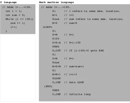
And now to the example: Suppose we want to add the integers 1 to 100, using re-petitive addition. Figure 4.2 gives a C language solution and a possible compilation into the Hack language.
Although the Hack syntax is more accessible than that of most machine lan-guages, it may still look obscure to readers who are not familiar with low-level pro-gramming. In particular, note that every operation involving a memory location requires two Hack commands: One for selecting the address on which we want to operate, and one for specifying the desired operation. Indeed, the Hack language consists of two generic instructions: anaddress instruction, also calledA-instruction, and a compute instruction, also called C-instruction. Each instruction has a binary representation, a symbolic representation, and an effect on the computer, as we now specify.
4.2.2 TheA-Instruction
TheA-instruction is used to set the A register to a 15-bit value:
A-instruction: @value // Wherevalueis either a non-negative decimal number // or a symbol referring to such number.
value(v¼0 or 1)
Binary: 0 v v v v v v v v v v v v v v v
This instruction causes the computer to store the specified value in the A register. For example, the instruction @5, which is equivalent to 0000000000000101, causes the computer to store the binary representation of 5 in the A register.
C language Hack machine language
// Adds 1+...+100. int i = 1; int sum = 0; While (i <= 100){
sum += i; i++; }
// Adds 1+...+100.
@i // i refers to some mem. location.
M=1 // i=1
@sum // sum refers to some mem. location.
M=0 // sum=0
(LOOP) @i
D=M // D=i
@100
D=D-A // D=i-100 @END
D;JGT // If (i-100)>0 goto END @i
D=M // D=i
@sum
M=D+M // sum=sum+i @i
M=M+1 // i=i+1 @LOOP
0;JMP // Goto LOOP (END)
@END
0;JMP // Infinite loop
4.2.3 TheC-Instruction
The C-instruction is the programming workhorse of the Hack platform—the in-struction that gets almost everything done. The inin-struction code is a specification that answers three questions: (a) what to compute, (b) where to store the computed value, and (c) what to do next? Along with the A-instruction, these specifications determine all the possible operations of the computer.
C-instruction: dest¼comp;jump // Either thedestorjumpfields may be empty. // Ifdestis empty, the ‘‘¼’’ is omitted;
// Ifjumpis empty, the ‘‘;’’ is omitted.
comp dest jump
Binary: 1 1 1 a c1 c2 c3 c4 c5 c6 d1 d2 d3 j1 j2 j3
The leftmost bit is the C-instruction code, which is 1. The next two bits are not used. The remaining bits form three fields that correspond to the three parts of the instruction’s symbolic representation. The overall semantics of the symbolic instruc-tiondest¼comp;jump is as follows. Thecompfield instructs the ALU what to com-pute. The destfield instructs where to store the computed value (ALU output). The jumpfield specifies a jump condition, namely, which command to fetch and execute next. We now describe the format and semantics of each of the three fields.
The Computation Specification The Hack ALU is designed to compute a fixed set of functions on the D, A, and M registers (where M stands for Memory[A]). The computed function is specified by thea-bit and the sixc-bits comprising the instruc-tion’s compfield. This 7-bit pattern can potentially code 128 different functions, of which only the 28 listed in figure 4.3 are documented in the language specification.
Recall that the format of theC-instruction is111a cccc ccdd djjj. Suppose we want to have the ALU compute D-1, the current value of the D register minus 1. According to figure 4.3, this can be done by issuing the instruction1110 0011 1000 0000(the 7-bit operation code is in bold). To compute the value ofD|M, we issue the instruction 1111 0101 0100 0000. To compute the constant 1, we issue the in-struction1110 1110 1000 0000, and so on.
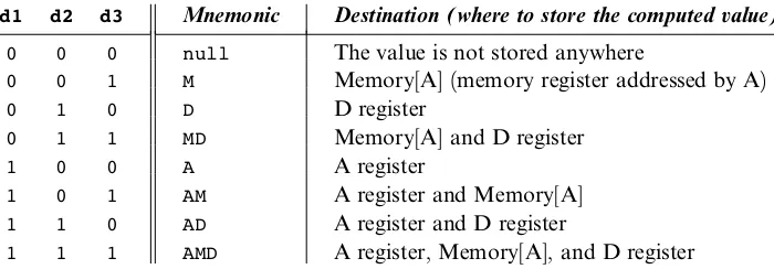
dest part (see figure 4.4). The first and secondd-bits code whether to store the com-puted value in the A register and in the D register, respectively. The thirdd-bit codes whether to store the computed value in M (i.e., in Memory[A]). One, more than one, or none of these bits may be asserted.
Recall that the format of the C-instruction is 111a cccc ccdd djjj. Suppose we want the computer to increment the value of Memory[7] by 1 and to also store the result in the D register. According to figures 4.3 and 4.4, this can be accomplished by the following instructions:
0000 0000 0000 0111 // @7
1111 1101 1101 1000 // MD=M+1
(whena=0)
compmnemonic c1 c2 c3 c4 c5 c6
(whena=1)
The first instruction causes the computer to select the memory register whose address is 7 (the so-called M register). The second instruction computes the value of Mþ1 and stores the result in both M and D.
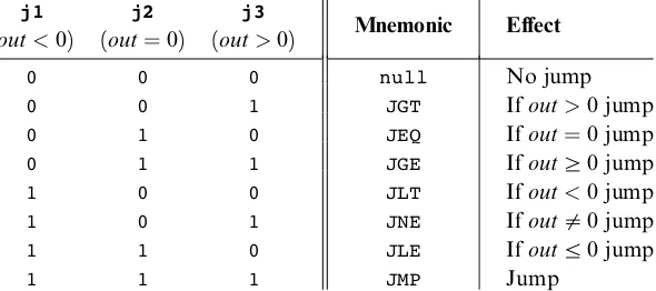
The Jump Specification Thejumpfield of theC-instruction tells the computer what to do next. There are two possibilities: The computer should either fetch and execute the next instruction in the program, which is the default, or it should fetch and exe-cute an instruction located elsewhere in the program. In the latter case, we assume that theAregister has been previously set to the address to which we have to jump.
Whether or not a jump should actually materialize depends on the three j-bits of thejumpfield and on the ALU output value (computed according to thecompfield). The firstj-bit specifies whether to jump in case this value is negative, the secondj-bit in case the value is zero, and the third j-bit in case it is positive. This gives eight possible jump conditions, shown in figure 4.5.
The following example illustrates the jump commands in action:
Logic Implementation
d1 d2 d3 Mnemonic Destination (where to store the computed value)
0 0 0 null The value is not stored anywhere
0 0 1 M Memory[A] (memory register addressed by A)
0 1 0 D D register
0 1 1 MD Memory[A] and D register
1 0 0 A A register
1 0 1 AM A register and Memory[A]
1 1 0 AD A register and D register
1 1 1 AMD A register, Memory[A], and D register
The last instruction (0;JMP) effects an unconditional jump. Since the C-instruction syntax requires that we always effect some computation, we instruct the ALU to compute 0 (an arbitrary choice), which is ignored.
Conflicting Uses of the A Register As was just illustrated, the programmer can use the A register to select either adata memorylocation for a subsequentC-instruction involving M, or an instruction memory location for a subsequent C-instruction involving a jump. Thus, to prevent conflicting use of the A register, in well-written programs a C-instruction that may cause a jump (i.e., with some non-zeroj bits) should not contain a reference to M, and vice versa.
4.2.4 Symbols
Assembly commands can refer to memory locations (addresses) using either con-stants orsymbols. Symbols are introduced into assembly programs in the following three ways:
m Predefined symbols: A special subset of RAM addresses can be referred to by any assembly program using the following predefined symbols:
Virtual registers: To simplify assembly programming, the symbolsR0toR15are predefined to refer to RAM addresses 0 to 15, respectively.
Predefined pointers: The symbolsSP,LCL, ARG,THIS, andTHAT are predefined to refer to RAM addresses 0 to 4, respectively. Note that each of these memory
j1
locations has two labels. For example, address 2 can be referred to using eitherR2or ARG. This syntactic convention will come to play in the implementation of the virtual machine, discussed in chapters 7 and 8.
I/O pointers: The symbols SCREEN and KBD are predefined to refer to RAM addresses 16384 (0x4000) and 24576 (0x6000), respectively, which are the base addresses of the screen and keyboard memory maps. The use of these I/O devices is explained later.
m Label symbols: These user-defined symbols, which serve to label destinations of goto commands, are declared by the pseudo-command ‘‘(Xxx)’’. This directive defines the symbol Xxxto refer to the instruction memory location holding the next command in the program. A label can be defined only once and can be used any-where in the assembly program, even before the line in which it is defined.
m Variable symbols: Any user-defined symbolXxxappearing in an assembly pro-gram that is not predefined and is not defined elsewhere using the ‘‘(Xxx)’’ com-mand is treated as a variable, and is assigned a unique memory address by the assembler, starting at RAM address 16 (0x0010).
4.2.5 Input/Output Handling
The Hack platform can be connected to two peripheral devices: a screen and a key-board. Both devices interact with the computer platform through memory maps. This means that drawing pixels on the screen is achieved by writing binary values into a memory segment associated with the screen. Likewise, listening to the key-board is done by reading a memory location associated with the keykey-board. The physical I/O devices and their memory maps are synchronized via continuous refresh loops.
// Draw a single black dot at the screen's top left corner: @SCREEN // Set the A register to point to the memory
// word that is mapped to the 16 left-most // pixels of the top row of the screen.
M=1 // Blacken the left-most pixel.
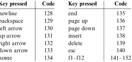
Keyboard The Hack computer interfaces with the physical keyboard via a single-word memory map located in RAM address 24576 (0x6000). Whenever a key is pressed on the physical keyboard, its 16-bit ASCII code appears in RAM[24576]. When no key is pressed, the code 0 appears in this location. In addition to the usual ASCII codes, the Hack keyboard recognizes the keys shown in figure 4.6.
4.2.6 Syntax Conventions and File Format
Binary Code Files A binary code file is composed of text lines. Each line is a se-quence of sixteen ‘‘0’’ and ‘‘1’’ ASCII characters, coding a single machine language instruction. Taken together, all the lines in the file represent a machine language program. The contract is such that when a machine language program is loaded into the computer’s instruction memory, the binary code represented by the file’snth line is stored in addressnof the instruction memory (the count of both program lines and memory addresses starts at 0). By convention, machine language programs are stored in text files with a ‘‘hack’’ extension, for example,Prog.hack.
Assembly Language Files By convention, assembly language programs are stored in text files with an ‘‘asm’’ extension, for example,Prog.asm. An assembly language
Key pressed Code Key pressed Code
newline 128 end 135
backspace 129 page up 136
left arrow 130 page down 137
up arrow 131 insert 138
right arrow 132 delete 139
down arrow 133 esc 140
home 134 f1–f12 141–152
file is composed of text lines, each representing either an instruction or a symbol declaration:
m Instruction: anA-instruction or aC-instruction.
m (Symbol): This pseudo-command causes the assembler to assign the label Symbolto the memory location in which the next command of the program will be stored. It is called ‘‘pseudo-command’’ since it generates no machine code.
(The remaining conventions in this section pertain to assembly programs only.)
Constants and Symbols Constantsmust be non-negative and are always written in decimal notation. A user-defined symbol can be any sequence of letters, digits, un-derscore (_), dot (.), dollar sign ($), and colon (:) that does not begin with a digit.
Comments Text beginning with two slashes (//) and ending at the end of the line is considered a comment and is ignored.
White Space Space characters are ignored. Empty lines are ignored.
Case Conventions All the assembly mnemonics must be written in uppercase. The rest (user-defined labels and variable names) is case sensitive. The convention is to use uppercase for labels and lowercase for variable names.
4.3
Perspective
The Hack machine language is almost as simple as machine languages get. Most computers have more instructions, more data types, more registers, more instruction formats, and more addressing modes. However, any feature not supported by the Hack machine language may still be implemented in software, at a performance cost. For example, the Hack platform does not supply multiplication and division as primitive machine language operations. Since these operations are obviously required by any high-level language, we will later implement them at the operating system level (chapter 12).
should note, however, that these are just syntactic details. For example, the+ char-acter plays no algebraic role whatsoever in the command D=D+M. Rather, the three-character string D+M, taken as a whole, is treated as a single assembly mnemonic, designed to code a single ALU operation.
One of the main characteristics that gives machine languages their particular flavor is the number of memory addresses that can appear in a single command. In this respect, Hack may be described as a ‘‘1
2address machine’’: Since there is no room to
pack both an instruction code and a 15-bit address in the 16-bit instruction format, operations involving memory access will normally be specified in Hack using two instructions: anA-instruction to specify the address and aC-instruction to specify the operation. In comparison, most machine languages can directly specify at least one address in every machine instruction.
Indeed, Hack assembly code typically ends up being (mostly) an alternating sequence ofA- andC-instructions, for example,@xxxfollowed byD=D+M,@YYY fol-lowed by0;JMP, and so on. If you find this coding style tedious or even peculiar, you should note that friendlier macro commands like D=D+M[xxx] and GOTO YYY can easily be introduced into the language, causing Hack assembly code to be more readable as well as about 50 percent shorter. The trick is to have the assembler translate these macro commands into binary code effecting@xxxfollowed byD=D+M, @YYYfollowed by0;JMP, and so on.
Theassembler, mentioned several times in this chapter, is the program responsible for translating symbolic assembly programs into executable programs written in bi-nary code. In addition, the assembler is responsible for managing all the system- and user-defined symbols found in the assembly program, and for replacing them with physical memory addresses, as needed. We return to this translation task in chapter 6, in which we build an assembler for the Hack language.
4.4
Project
Objective Get a taste of low-level programming in machine language, and get acquainted with the Hack computer platform. In the process of working on this project, you will also become familiar with the assembly process, and you will ap-preciate visually how the translated binary code executes on the target hardware.
Contract Write and test the two programs described in what follows. When exe-cuted on the CPU emulator, your programs should generate the results mandated by the test scripts supplied in the project directory.
m Multiplication Program(Mult.asm): The inputs of this program are the current values stored inR0andR1(i.e., the two top RAM locations). The program computes the product R0*R1 and stores the result in R2. We assume (in this program) that R0>=0,R1>=0, andR0*R1<32768. Your program need not test these conditions, but rather assume that they hold. The suppliedMult.tstandMult.cmpscripts will test your program on several representative data values.
m I/O-Handling Program (Fill.asm): This program runs an infinite loop that listens to the keyboard input. When a key is pressed (any key), the program blackens the screen, namely, writes ‘‘black’’ in every pixel. When no key is pressed, the screen should be cleared. You may choose to blacken and clear the screen in any spatial order, as long as pressing a key continuously for long enough will result in a fully blackened screen and not pressing any key for long enough will result in a cleared screen. This program has a test script (Fill.tst) but no compare file—it should be checked by visibly inspecting the simulated screen.
Steps We recommend proceeding as follows:
0. The assembler and CPU emulator programs needed for this project are available in the toolsdirectory of the book’s software suite. Before using them, go through the assembler tutorial and the CPU emulator tutorial.
1. Use a plain text editor to write the first program in assembly, and save it as projects/04/mult/Mult.asm.
2. Use the supplied assembler (in either batch or interactive mode) to translate your program. If you get syntax errors, go to step 1. If there are no syntax errors, the assembler will produce a file calledprojects/04/mult/Mult.hack, containing bi-nary machine instructions.
3. Use the supplied CPU emulator to test the resultingMult.hackcode. This can be done either interactively, or batch-style using the suppliedMult.tstscript. If you get run-time errors, go to step 1.
Debugging Tip The Hack language is case sensitive. A common error occurs when one writes, say,@fooand@Fooin different parts of the program, thinking that both commands refer to the same variable. In fact, the assembler treats these symbols as two completely different identifiers.
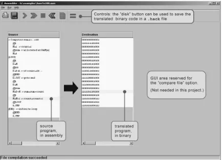
The Supplied Assembler The book’s software suite includes a Hack assembler that can be used in either command mode or GUI mode. The latter mode of operation allows observing the translation process in a visual and step-wise fashion, as shown in figure 4.7.
The machine language programs produced by the assembler can be tested in two different ways. First, one can run the .hack program in the CPU emulator.
Alternatively, one can run the same program directly on the hardware, by loading it into the computer’s instruction memory using the hardware simulator. Since we will finish building the hardware platform only in the next chapter, the former option makes more sense at this stage.
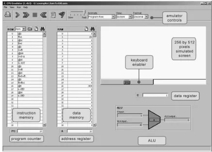
The Supplied CPU Emulator This program simulates the Hack computer platform. It allows loading a Hack program into the simulated ROM and visually observing its execution on the simulated hardware, as shown in figure 4.8.
![Figure 4.3Thethe memory location addressed by A, namely, to Memory[A]. The symbols compute field of the C-instruction](https://thumb-ap.123doks.com/thumbv2/123dok/3002971.1363807/11.576.143.454.64.326/figure-thethe-location-addressed-memory-symbols-compute-instruction.webp)