IMAGE DITHERING BASED ON THE WAVELET
TRANSFORM
by Ovidiu Cosma
Abstract: In this paper, a method for compensating the softening effect of the error diffusion algorithms, and a new dithering technique that emphasizes the details of images and is based entirely on the wavelet transform, are presented.
Keywords: Dithering, Wavelets
Introduction
Image dithering is a technique to create the illusion of color depth in images displayed on devices with a limited color palette. The colors that are not available in the palette are approximated by a mixture of pixels from the palette. The human visual system averages the colors in a neighborhood of the point of interest thus creating the illusion of more colors.
There are three types of dithering algorithms:
− Noise dithering
− Ordered dithering
− Error diffusion
The noise dithering algorithms add a white random number to each pixel of the original image. This is a very simple process, but the result is a little “noisy”. In the case of the ordered dithering, the image is represented with a set of predefined patterns. Figure 1 contains an example of a pattern set that can be used to represent 5 different gray levels. The disadvantage of this type of algorithms is that the processed images loose their natural aspect, because certain textures generated in the dithering process can be easily observed.
The error diffusion algorithms build dithering patterns dynamically, based on error dispersion. One of the best-known algorithms of this type is the Floyd – Steinberg dithering [3], which performs the following operations:
For each pixel of the image choose the closest color from the available palette, then replace the pixel with the palette color, calculate the representation error and distribute it to the neighboring pixels that have not been visited yet.
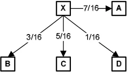
The image can be scanned in the normal left – right, top-bottom order, or in the left – right, right – left order, which is preferred because it generally produces fewer artifacts. Many different filters can be used to distribute the error among the neighboring pixels. The Floyd – Steinberg filter is presented in figure 2, where X represents the current pixel, and A, B, C and D represent the neighboring pixels that receive 7/16, 3/16, 5/16 and 1/16 of the error. When scanning in the right – left order, the filter is reversed.
Figure 2: The Floyd – Steinberg error diffusion filter. 1. Image dithering application
The main drawback of the error diffusion techniques is that the resulting images are softer than the original, because each pixel color is represented as the average of a group of pixels. In [5] is presented a method of enhancing the image contours by dividing the image in 2 x 2 pixel blocks and diffusing the average of the pixel errors in each block to the neighboring blocks.
Figure 3: Image dithering application.
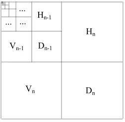
The Discrete Wavelet Transform (DWT) module decomposes the image in a hierarchy of coefficients, placed in several subbands [1], [4]. Their position is presented in figure 4. The coefficient placed in the upper-left corner of the array represents the general average of the image, and the other ones are detail coefficients corresponding to various resolutions. Each subband is composed of three groups of coefficients: Hk, Vk and Dk, representing the
horizontal, vertical and diagonal oscillations, where k is the number of the subband. The last subband contains the finest details of the image.
Hn
Vn Dn
Dn-1
Vn-1
... ... ...
Hn-1
Figure 4: Localization of the image subbands.
number of the subband ci,j belongs to and pk is the weight corresponding to
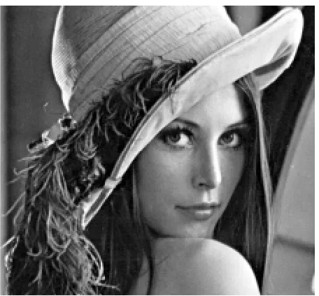
Figure 7 presents a set of binary images, obtained by applying different dithering techniques to the image presented in figure 6. The result of the original Floyd – Steinberg error diffusion algorithm is presented in figure 7a.
The images presented in figures 7b and 7c are the result of subband filtering followed by error diffusion. In the case of the image in figure 7b the contours of the original image were enhanced using the weights in table 1b. The contrast of the image is not affected by this operation. In the case of the image in figure 7c both the contours and the contrast of the original image were enhanced using the weights in table 1c. The contrast increased because besides the finest details, some of the lower subbands were also amplified.
3. Wavelet dithering
If the high subbands are strongly amplified, the error diffusion algorithm is no longer needed, because the result of the inverse DWT is an image that contains almost only black and white pixels. Thus we can consider that filtering of the image subbands represents a new dithering method, that can be used in the situations in which emphasizing of all the details is more important than the photographic quality of the result. The contrast of the processed image can be controlled with the lower subbands weights.
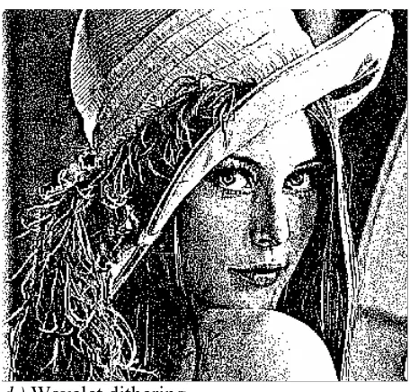
The image in figure 7d is the result of the inverse DWT, in the case of applying the weights in table 1d. No error diffusion algorithm was used. The few gray pixels in the inverse DWT image were eliminated with a simple thresholding operation. This image contains the highest level of details (notice the texture of the hat).
There are little differences between the various DWT filters [2], [6], [7], when used for dithering, excepting the Haar filter that produces annoying distortions. In the case of the images in figures 7b – 7d, the Villasenor 18/10 digital filter was used.
weight pk
0
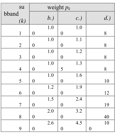
Figure 5: Subband weights for enhancing the details of images:
b.) contour enhancement, c.) contrast and contour enhancement, d.)
wavelet dithering.
4. Conclusions
Enhancing the details of images can compensate the softening effect of the error diffusion algorithms. In this article a technique based on the DWT and subband filtering was presented, that allows the control of both the level of details and the contrast of images, prior error diffusion.
If the last subbands are strongly amplified, the result of the inverse DWT is an image that contains only black and white pixels. This property can be used for image dithering, if the accented emphasize of details is preferred to the photographic quality of the image. We named this new technique wavelet
Figure 6: Original image.
b.) Detail enhancement
d.) Wavelet dithering
Figure 7: Dithered images.
References:
1. O. Cosma, Wavelet Transform application in image compression, Buletinul
Ştiinţific al Universităţii din Baia Mare seria B (2000)
2. Daubechies, Ten Lectures on Wavelets, SIAM Publ., Philadelphia (1992) 3. R. Floyd, L. Steinberg, An adaptive Algorithm for Spatial Grey-Scale, Proc. of the SID, Vol. 17, No. 2 (1976) .
4. L. M. Reissell, Multiresolution and Wavelets, SIGGRAPH’95 Course Notes (1995)
5. O. Veryovka and J. W. Buchanan. Texture-Based Dither Matrices, Computer Graphics Forum 19:1 (2000).
6. Signal and Image Processing Group, University of Bath, The Bath Wavelet
Warehouse , http://dmsun4.bath.ac.uk
7. A Bank of Wavelet Filters, http://www.isye.gatech.edu/ ~brani/.public.html
/Wiley/filters.html Author: