Interaction between electrostatic collisionless shocks generates
strong magnetic fields
E. Boella,1, 2,∗ K. Schoeffler,2 N. Shukla,2 G. Lapenta,1 R. Fonseca,2, 3 and L. O. Silva2
1Mathematics department, KU Leuven, Leuven, Belgium
2GoLP/Instituto de Plasmas e Fus˜ao Nuclear,
Instituto Superior T´ecnico, Universidade de Lisboa, Lisbon, Portugal
3DCTI/ISCTE, Instituto Universitario de Lisboa, Lisbon, Portugal
(Dated: September 19, 2017)
Abstract
The head-on collision between electrostatic shocks is studied via multi-dimensional
Particle-In-Cell simulations. It is found that the shock velocities drop significantly and a strong magnetic field
is generated after the interaction. This transverse magnetic field is due to the Weibel instability
caused by pressure anisotropies due to longitudinal electron heating while the shocks approach each
other. Finally, it is shown that this phenomenon can be explored in the laboratory with current
laser facilities within a significant parameter range.
Collisionless shocks are ubiquitous in space and astrophysics, where they are considered efficient particle accelerators and they are often invoked to explain, for instance, the cosmic ray spectrum or the emission from gamma-ray bursts [1, 2]. During the past few years, the tremendous advances in computer power and numerical modelling have fostered innova-tive and very detailed kinetic simulations of shocks, allowing for the comprehension of many aspects of the shock micro-physics, from shock formation to particle acceleration [3–8]. How-ever, to date almost no theoretical, computational, or experimental studies investigating the interaction among collisionless shocks are available. The phenomenon is equally important and quite pervasive in astrophysics: the internal shock model of GRB is perhaps the most well-known example where shock collision is thought to play a role [9]. Furthermore, very recently shock collision has been observed for the first time in the extragalactic jet of the nearby radio galaxy 3C 264 [10].
In order to study the interaction of two collisionless electrostatic shocks, we performed a series of one- and two-dimensional (1D and 2D, respectively) simulations using the PIC code OSIRIS [25]. A plasma composed by uniformly hot Maxwellian electrons and cold hydrogen ions with realistic charge-to-mass ratio (akin to a laser-generated system) is considered. The two species do not have any initial drift velocity (this is a valid assumptions when considering laser pulses interacting with near critical density targets, where most of the laser energy will be transferred to the plasma in the form of electron heating [16]). The plasma density profile presents two perfectly symmetric sharp discontinuities (see inset in Fig. 1 (a)). They constitute the jump in density that triggers the shock formation, similarly to that explained in [17, 26]. We have carried out simulations, considering electron temperatures in the range
Te = 0.2·10−3−1.5 MeV and initial density jumps in the intervalσ ≡n0,M/n0,m= 3.33−10,
where M and m indicate the highest and the lowest density respectively. The biggest simulation box adopted was 4800c/ωp long and 240c/ωp wide, with c/ωp the electron skin
depth, cthe speed of light in vacuum, ωp ≡
p 4πe2n
0,M/me the electron plasma frequency,
e the elementary charge andme the electron mass. The system is numerically resolved with
4 cells per skin depth or electron Debye length λD ≡
p
kBTe/4πe2n0,M, where kB is the
Boltzmann constant, and the temporal step is chosen to satisfy the Courant condition. In order to model the plasma dynamics correctly 36 (or 1000 in 1D) particles per cell and quartic interpolation were employed. Periodic boundary conditions have been used, but the simulation box is large enough that they do not interfere with the plasma dynamics.
In Fig. 1, the main stages of a typical simulation are reported. In this case,Te= 1.5 MeV
andσ = 10 were used. When the more dense plasma expands into the less dense component, it drives several non linear-waves that eventually develop into two shock waves streaming towards each other in opposite directions. The shock structures are clearly recognisable at x1 ≃ ±35c/ωp in Figs. 1 (a) and (d), which depict the longitudinal ion phase space
and the longitudinal electric field E1 at t = 335ωp−1. In particular, E1 presents a double layer structure, which is a typical signature of electrostatic shocks [27–29]. The shock waves collide in the middle of the simulation box (x1 = 0) at t = 913.5ωp−1 (Figs. 1 (b) and (e)).
x1 [c / ωp]
FIG. 1. Longitudinal ion phase space (a-c), longitudinal electric fieldE1 (d-f) and transverse
mag-netic field B3 (g-i) at shock formation (t= 335ωp−1, first column), shock collision (t= 913.5ωp−1,
second column) and after the interaction (t= 1309ω−1
p , third column). The inset in (a) shows the
initial density profile with the sharp discontinuities which trigger the formation of the two
counter-propagating shocks. The black solid lines in (d-f) are an average ofE1 along the x2 direction.
middle of the simulation box presents an intense filamentary structure, which has developed only after the interaction. The field is confined in a small region of the simulation box, between x1 = [−30, 30]c/ωp corresponding to the downstream of the shocks. The filaments
are characterised by a wavelength λ ≃ 50.7c/ωp. The field reaches a maximum at around
t≃1309ω−1
p and then starts to decay.
We measured the velocity of the shocks before and after the interaction. Results are shown in Fig. 2 (a), where the evolution of the ion density averaged along the x2 direction is plotted. The shocks move at a constant speed vs = ±0.056c corresponding to a Mach
number M = vs/cs = 1.4, where cs =
p
kBTe/mi is the sound speed for ions of mass mi,
in excellent agreement with the theoretical model in [30]. After the collision, the speed of both shocks drops to vs ≃ ±0.032c, which corresponds to about 42% of its initial value.
x1
FIG. 2. Evolution of the ion density for a 2D (a) and a 1D simulation (b). The values in (a) result
from an average along the x2 direction. The transversely averaged density is shown in detail at
shock formation (t = 335ω−1
p , Fig. (c)) and after the collision (t= 1309ωp−1, Fig. (d)). The red
dashed lines follow the shocks and their slope measures the shock speed, which isvs =±0.056cand
±0.032c before and after the collision respectively in (a) and vs = ±0.058c and ±0.054c before
and after the collision respectively in (b).
paragraphs. For comparison, we report the same results as obtained from a 1D simulation (Fig. 2 (b)), where, due to the geometry, the growth of modes perpendicular to x1 is inhibited and therefore no B3 is observed. In this case the shocks only slightly slow down: their velocity passes fromvs=±0.058ctovs ≃ ±0.054cafter the collision. We verified that
despite the slowdown, the nature of the shock waves remain unchanged: the electric field maintains the double layer structure (Figs. 1 (d) and (f)), the density jump conditions for low Mach number shocks [32] are satisfied (Figs. 2 (c) and (d)) and the waves are moving withM > 1. These results indicate that the interaction of collisionless shocks is an inelastic process and that the waves lose energy during the collision much more substantially in 2D than 1D. Given this and the prediction in [31], we expect that in 3D simulations the shock velocity after the collision would be even lower.
To gain insight over what happens immediately after the collision, we have checked the electron distribution functions f(p1) and f(p2), with p1 and p2 longitudinal and traverse momentum respectively, in the interaction region (Fig. 3) and far from it (not presented here) much before, during and after the encounter. At the beginning of the simulation,
At t = 913.5ω−1
p and around x1 = 0, f(p1) is much broader than f(p2) (Fig. 3 (b)). The longitudinal field E1, which is far from being uniform in the region corresponding to the upstream of the two shocks, slightly before the collision, heavily heats the electrons in the longitudinal direction. This does not happen in the downstream of the shocks, where f(p1) andf(p2) remain equivalent. We observe that both our simulation setup and our results are fundamentally different from [30]. In [30], strong longitudinal electron heating leading to Weibel generated fields was detected in the downstream of an electrostatic shock driven by the interpretation of plasma shells moving towards each other with an equal and opposite drift velocity; simulations of single shocks triggered by a density jump in plasmas with no drift show no magnetic field evidence in the downstream region and lead to constant shock velocities [17, 18]. Further in time, the distribution functions in what is now the downstream of the shocks become very similar, but their spread is bigger than in the far upstream (Fig. 3 (c)).
The electron isotropization could then explain the agreement between the slowdown of the shock waves and [31]. In fact, in the reference frame of the shock, the electrons are moving toward the shock with longitudinal velocity −vs and the magnetic field B3 bends them in the x2 direction, thus equally equipartitioning their kinetic energy among the two in-plane directions. As a result, the longitudinal component of their velocity decreases as 1/√2, which translates in the same shock slow-down when moving back to the simulation reference frame (e.g. downstream reference frame). We computed the anisotropy
∆ = αk
FIG. 3. Electron distribution functions f(p1) (red dashed) and f(p2) (black solid) in the middle
of the simulation box (x1 = 0) at the beginning of the simulation (a), collision time (b) and much
with αk and α⊥ defined according to [33]:
Te⊥ mec2
= 1
α⊥, (2)
Tek mec2
= 1
αk
" 1 +
αk α⊥
K1 αk
αkK2 αk
#−1
, (3)
where Kn indicates the modified Bessel function of the second kind of order n and Te⊥ and Tek are calculated from the temperature tensor T performing a matrix diagonalization as
described in [34]. The result of the latter operation is such thatT1,1 =Tek andT2,2 =T3,3 =
Te⊥, where the symbolsk and ⊥ refer to parallel and perpendicular to the shock speed and
identify the direction with the higher and lower temperature, respectively. Figure 4 (a) reports ∆ in the simulation box att = 974.4ω−1
p , when the anisotropy reaches its maximum
∆max = 0.7. It is interesting to observe that, apart from the central region, the anisotropy in the rest of the domain is almost zero. Given α⊥ ≃ 0.19, ∆ = 0.7 and the wavenumber
k = 2π/λ= 0.12ωp/c as provided by the simulation and employing the formula in [33], we
have computed the growth rate of the electron Weibel instability Γtheory = 0.019ωp. We have
compared the theoretical prediction with numerical results. Figure 4 (b) shows the evolution of the energy of B3 in the region between x1 =−30c/ωp and x1 = 30c/ωp. The magnetic
field energy has an exponential growth until t≃1309ω−1
p , where it reaches a maximum and
then it starts decaying. The slope of the linear phase allows for inferring the growth rate of the instability, which is measured to be 0.02ωp in excellent agreement with the theory. This
is a strong evidence that the Weibel instability is at play and causes the magnetic field to grow, leading to the isotropization of the electrons. However, we notice that the simulation wavenumber and the relative growth rate do not correspond to the fastest growing mode. We speculate that this is probably due to the fact that the latter rises within a very short period of time and saturates quickly; thus the only modes surviving and observable are those at lower ks. The evolution of the Fourier transform of B2
3 (not shown here) displays indeed low energetic modes at k ≃ 0.25ωp/c, which saturate in a time interval of ≈ 100ω−p1 after
the collision.
x2
superimposed red dashed line indicates the theoretical growth rate Γtheory= 0.019ωp.
the Weibel instability, whose modes are perpendicular to x1, cannot occur and therefore the shock velocity is only slightly decreased by the longitudinal heating.
The ability to drive two counter-propagating shocks experimentally, whose collision will lead to the growth of the Weibel instability, is connected to the laser intensity and the target maximum density and thickness. In fact, these parameters affect the initial density jump
σ and electron temperature Te, which trigger the shock formation and determine the shock
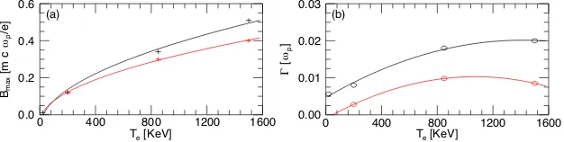
initial speed, thus influencing the instability to be observed. To understand the dependence of the maximum amplitude of the magnetic field and the growth rate of the instability, both measurable in experiments, on Te and σ, we have performed a parameter scan varying
these quantities (Fig. 5). The field amplitude at saturation varies as √Te (Fig. 5 (a)):
saturation of the field is expected when the magnetic pressure ∝ B2 equals the plasma pressure ∝ Te. The growth rate values are fitted by quadratic curves (Fig. 5 (b)); the
quadratic trend can be explained by the bigger electron inertia of more energetic electrons. Given the higher inertia, they are more difficult to isotropise and the time required for the Lorentz force to accomplish this longer. It is then expected that for even higher temperature,
Bmax
FIG. 5. Maximum amplitude of the magnetic field (a) and instability growth rate (b) versusTe for
σ = 10 (black) and σ = 5 (red) as given by the simulations. The magnetic field amplitude scales
not of interest for this context, Γ will decrease with increasing Te. In order to compare our
findings with current laser experiments, we compute the laser normalised intensity using the ponderomotive scaling formula [35]. To reach the considered electron temperatures, laser pulses with normalised vector potential a0 = (kBTe/mec2+ 1)
2
−1≃ 1−14 are necessary. We note that such intensities are already or will be soon available, creating an opportunity to probe the Weibel instability in the laboratory. The other crucial factor to drive an electrostatic shock is the formation of a sharp density variation in the plasma [16]. Sharp gradients comparable to those employed in our simulations can be easily obtained in the laboratory using thin targets whose density profile reaches a maximum close to the critical density [17]. In fact, the laser will be stopped around the critical density and its radiation pressure will contribute to further steepen the density, which will lead to the formation of the shock.
Concluding, we have performed fully kinetic simulations of the interaction between two electrostatic shocks. The resulting head-on collision was highly inelastic, with the shocks slowing down to up to 50% with respect to their initial velocity. The decrease in shock velocity is due to a strong magnetic field in the direction perpendicular to the simulation plane produced by the Weibel instability. The temperature anisotropy, which drives the electron Weibel instability after the collision, is caused by an intense longitudinal electron heating occurring upstream of the shocks, as they approach each other. The magnetic field starts decaying when the electron distributions are again isotropic. We have confirmed the magnetic field growth due to the Weibel instability for different initial plasma conditions attainable with available or near future laser beams, thus suggesting that the physics of shock collision can currently be investigated in the laboratory. For instance, the 10µm CO2 laser systems available at University of California at Los Angeles [36] and at the Accelerator Test Facility at the Brookhaven National Laboratory [37] with a0 in the range 1.5−2.5 would easily allow for testing this setup with commercial hydrogen gas jets. In principle the scheme could be tested also with near-infrared lasers, however in this case targets with higher densities are required. Finally, we note that the proposed setup allows for probing the electron Weibel instability in a fully collisionless regime in the laboratory, similarly to what has previously been done for the ion Weibel instability [38, 39].
Fund KU Leuven, GOA scheme and Space Weaves RUN project) and the US Air Force EOARD Project (FA2386-14-1-0052). Simulations were performed at the Accelerates clus-ter (Lisbon, Portugal) and on the supercompuclus-ter Marconi (Cineca, Italy) under PRACE allocations.
[1] T. Piran, Review of Modern Physics 4, 1143 (2005).
[2] F. C. Jones and C. Ellison, Space Science Reviews 58, 259 (1991).
[3] C. Ruyer, L. Gremillet, G. Bonnaud, and C. Riconda, Physical Review Letters 117, 065001
(2016).
[4] A. Bret, A. Stockem, R. Narayan, and L. O. Silva, Physics of Plasmas21, 072301 (2014).
[5] A. Bret, A. Stockem, F. Fiuza, C. Ruyer, L. Gremillet, R. Narayan, and L. O. Silva, Physics
of Plasmas 20, 042102 (2013).
[6] S. F. Martins, R. A. Fonseca, L. O. Silva, and W. B. Mori, The Astrophysical Journal Letters
695, L189 (2009).
[7] A. Spitkovsky, The Astrophysical Journal Letters 682, L5 (2008).
[8] A. Spitkovsky, The Astrophysical Journal Letters 673, L39 (2008).
[9] M. J. Rees, Monthly Notices of the Royal Astronomical Society 184, 61P (1978).
[10] E. T. Meyer, M. Geprganopoulos, W. B. Sparks, E. Perlman, R. P. van der Marel, J. Anderson,
S. Sohn, J. Biretta, C. Norman, and M. Chiaberge, Nature 521, 495 (2015).
[11] C. A. J. Palmer, N. P. Dover, I. Pogorelsky, M. Babzien, G. I. Dudnikova, M. Ispiriyan, M. N.
Polyanskiy, J. Schreiber, P. Shkolnikov, V. Yakimenko, and Z. Najmudin, Physical Review
Letters 106, 014801 (2011).
[12] D. Haberberger, S. Tochitsky, F. Fiuza, C. Gong, R. A. Fonseca, L. O. Silva, W. B. Mori,
and C. Joshi, Nature Physics 8, 95 (2012).
[13] O. Tresca, N. P. Dover, N. Cook, C. Maharjan, M. N. Polyanskiy, Z. Najmudin, P. Shkolnikov,
and I. Pogorelsky, Physical Review Letters 115, 094802 (2015).
[14] P. Antici, E. Boella, S. N. Chen, D. S. Andrews, M. Barberio, J. B¨oker, F. Cardelli, J. L.
Feugeas, M. Glesser, P. Nicola¨ı, L. Romagnani, M. Sciscio, M. Starodubtsev, O. Willi, J. C.
(2017), arXiv:1708.02539.
[15] S. N. Chen, M. Vranic, T. Gangolf, E. Boella, P. Antici, M. Bailly-Grandvaux, P. Loiseau,
H. P´epin, G. Revet, J. J. Santos, A. M. Schroer, M. Starodubtsev, O. Willi, L. O. Silva, E. d.
Humi`eres, and J. Fuchs, ArXiv e-prints (2017), arXiv:1708.02492.
[16] F. Fi´uza, A. Stockem, E. Boella, R. A. Fonseca, L. O. Silva, D. Haberberger, S. Tochitsky,
C. Gong, W. B. Mori, and C. Joshi, Physical Review Letters 109, 215001 (2012).
[17] F. Fi´uza, A. Stockem, E. Boella, R. A. Fonseca, L. O. Silva, D. Haberberger, S. Tochitsky,
W. B. Mori, and C. Joshi, Physics of Plasmas 20, 056304 (2013).
[18] E. Boella, F. Fi´uza, A. Stockem Novo, R. Fonseca, and L. O. Silva, “Numerical optimization
study of shock wave acceleration,” (2017), to be submitted.
[19] H.-S. Park, C. M. Huntington, F. Fiuza, R. P. Drake, D. H. Froula, G. Gregori, M. Koenig,
N. L. Kugland, C. C. Kuranz, D. Q. Lamb, M. C. Levy, C. K. Li, J. Meinecke, T. Morita,
R. D. Petrasso, B. B. Pollock, B. A. Remington, H. G. Rinderknecht, M. Rosenberg, J. S.
Ross, D. D. Ryutov, Y. Sakawa, A. Spitkovsky, H. Takabe, D. P. Turnbull, P. Tzeferacos,
S. V. Weber, and A. B. Zylstra, Physics of Plasmas 22, 056311 (2015).
[20] H.-S. Park, J. S. Ross, C. M. Huntington, F. Fiuza, D. Ryutov, D. Casey, R. P. Drake,
G. Fiksel, D. Froula, G. Gregori, N. L. Kugland, C. Kuranz, M. C. Levy, C. K. Li, J. Meinecke,
T. Morita, R. Petrasso, C. Plechaty, B. Remington, Y. Sakawa, A. Spitkovsky, H. Takabe,
and A. B. Zylstra, Journal of Physics: Conference Series 688, 012084 (2016).
[21] J. S. Ross, D. P. Higginson, D. Ryutov, F. Fiuza, R. Hatarik, C. M. Huntington, D. H.
Kalantar, A. Link, B. B. Pollock, B. A. Remington, H. G. Rinderknecht, G. F. Swadling, D. P.
Turnbull, S. Weber, S. Wilks, D. H. Froula, M. J. Rosenberg, T. Morita, Y. Sakawa, H. Takabe,
R. P. Drake, C. Kuranz, G. Gregori, J. Meinecke, M. C. Levy, M. Koenig, A. Spitkovsky, R. D.
Petrasso, C. K. Li, H. Sio, B. Lahmann, A. B. Zylstra, and H.-S. Park, Physical Review Letters
118, 185003 (2017).
[22] E. S. Weibel, Phys. Rev. Lett.2, 83 (1959).
[23] A. Bret, The Astrophysical Journal 699, 990 (2009).
[24] A. Bret, L. Gremillet, and M. E. Dieckmann, Physics of Plasmas17, 120501 (2010).
[25] R. A. Fonseca, L. O. Silva, F. S. Tsung, V. K. Decyk, W. Lu, C. Ren, W. B. Mori, S. Deng,
S. Lee, T. Katsouleas, and J. C. Adam, Lecture Notes in Computer Science2331, 342 (2002).
and Controlled Fusion 52, 025001 (2010).
[27] R. Z. Sagdeev,Review of plasma physics, Vol. 4 (Consultans Bureau, 1966).
[28] G. Sorasio, M. Marti, R. Fonseca, and L. O. Silva, Physical Review Letters96, 045005 (2006).
[29] A. Stockem, E. Boella, F. Fiuza, and L. O. Silva, Physical Review E 87, 043116 (2013).
[30] A. Stockem, T. Grismayer, R. A. Fonseca, and L. O. Silva, Physical Review Letters 113,
105002 (2014).
[31] N. Shukla, K. Schoeffler, J. Vieira, R. A. Fonseca, and L. O. Silva, “Influence of plasma
instabilities on interpenetrating plasma clouds as a test for electromagnetic dark matter
self-interactions,” (2017), to be submitted.
[32] D. W. Forslund and J. P. Freidberg, Physical Review Letters27, 1189 (1971).
[33] P. H. Yoon, Physics of Plasmas 14, 024504 (2007).
[34] K. Schoeffler and L. O. Silva, ArXiv e-prints (2017), arXiv:1707.06390.
[35] S. C. Wilks, W. L. Kruer, M. Tabak, and A. B. Langdon, Physical Review Letters 69, 1383
(1992).
[36] D. Haberberger, S. Tochitsky, and C. Joshi, Optics Express 18, 17865 (2010).
[37] M. N. Polyanskiy, I. V. Pogorelsky, and V. Yakimenko, Optics Express19, 7717 (2011).
[38] W. Fox, G. Fiksel, A. Bhattacharjee, P.-Y. Chang, K. Germaschewski, S. X. Hu, and P. M.
Nilson, Physical Review Letters 111, 225002 (2013).
[39] C. M. Huntington, F. Fiuza, J. S. Ross, A. B. Zylstra, R. P. Drake, D. H. Froula, G. Gregori,
N. L. Kugland, C. C. Kuranz, M. C. Levy, C. K. Li, J. Meinecke, T. Morita, R. Petrasso,
C. Plechaty, B. A. Remington, D. D. Ryutov, Y. Sakawa, A. Spitkovsky, H. Takabe, and