Experimental Study of DQPSK Modulation
on SDR Platform
Eko Marpanaji1, Bambang Riyanto2, Armein Z.R. Langi2, Adit Kurniawan2 Andri Mahendra2, Thay Liung2
ITB Research Center on ICT
Institut Teknologi Bandung, Jl. Ganesha 10 Bandung 40132, Indonesia Tel. +62-22-425-4034
1[email protected], 2 [email protected], [email protected], [email protected],
[email protected], [email protected]
Abstract— This Paper addresses Differential Quadriphase Shift Keying (DQPSK) modulation implemented on SDR platform for the development of digital data communications based on SDR. DQPSK modulation performance perceived at Packet Error Rate (PER) is evaluated in terms of Eb/No or S/N ratio, carrier frequency, bit rate, gain, roll-off factor of root Nyquist filter or root raised cosine filter, and of size of payload from delivered data. Based on this results, the smallest PER could be obtained by setting Eb/No value which is greater than 20 dB, carrier frequency of at least 0,3 MHz, optimum bit rate of 200 kbps, optimum range payload size of 2000 up to 4000 bytes, and roll-off factor of Nyquist or root-raised cosine filter of 0.4.
Index Terms— Differential quadriphase shift keying, packet error rate, root raised cosine, software-defined radio.
I. INTRODUCTION
This paper describes the implementation of Differential Quadriphase Shift Keying (DQPSK) modulation scheme for communicating of digital data on Software-Defined Radio (SDR) platform. This performance evaluation of DQPSK modulation scheme is also as a part of the current research in building SDR platform which can be reconfigured, including answering the research question of “How to design SDR platform using commodity components.”
In this research, we investigated the performance of DQPSK modulation scheme implemented on SDR platform using Universal Software Radio Peripheral
(USRP) from GNU Radio. DQPSK modulation scheme is chosen in this research because the QPSK and DQPSK modulation is also widely used in recent wireless and cellular communication systems such as Satellite, CDMA, and cable modem.
Chen (2007) investigated a performance of
Quadriphase Shift Keying (QPSK) modulation scheme to send a video digital data. All algorithms are modeled and simulated in Matlab, and the future works of that research is integrated those model into GNU Radio SDR platform using USRP[1]. Thus, the investigation of QPSK modulation scheme performance and its variants,
including DQPSK, on SDR platform using USRP is still needed.
The rest of this paper is organized as follows. Section 2 presents the DQPSK modulation scheme. Section 3 presents system configuration used in this research. Section 4 presents DQPSK implementation and test result. Finally, Section 5 is conclusion.
II. DIFFERENTIAL QUADRIPHASE SHIFT KEYING (DQPSK)
MODULATION
DQPSK modulation is a variant of π 4-QPSK modulation scheme, which differential encoding is added to the bits encoding prior to the modulation. Differential means that the information is not carried by the absolute state; it is carried by the transition between states. The advantage of using differential encoding is free from phase ambiguity if the constellation is rotated by some effect in the communications channel which the signal passes through. This problem can be overcome by using the data to change rather than set the phase. The QPSK modulation scheme using differential encoding is usually called as π 4-DQPSK or DQPSK.
The equation differential encoder to produce symbols is:
k k
k s b
s = −1⊕ (1)
where sk is current output symbol, sk−1 is previous
output symbol, and bkis current bit input. The ⊕ sign
indicate modulo-2 operation. So sk only changes state
(from binary '0' to binary '1' or from binary '1' to binary '0') if bk is a binary '1'. Otherwise it remains in its
1
the 180° phase ambiguity does not matter.
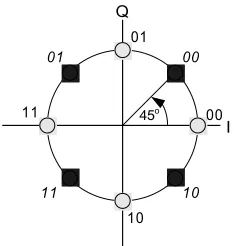
The DQPSK modulation format uses two QPSK constellations offset by 45 degrees (π/4 radians) as depicted in Fig. 1. Transitions must occur from one constellation to the other, or each DQPSK symbol will reside in one of eight points in the constellation diagram. This guarantees that there is always a change in phase at each symbol, making clock recovery easier. The data is encoded in the magnitude and direction of the phase shift, not in the absolute position on the constellation.
45o
Fig. 1. DPSK constellation diagram with identical Gray coding rotated by 45o
Table 1 summarizes a possible set of relationships between the phase transitions in the DQPSK modulation scheme and the incoming Gray code dibits[2].
Table 1. Correspondence between input dibit and phase change for DQPSK modulation
As mentioned above, DQPSK used root Nyquist filter or root raised cosine filter as a pulse-shaping filter. This filter is used to reduces a number of spurious signals or to control the shape of digital data. The time response of Nyquist filter is determined by equation [3]:
where α is roll-off factor of root raised cosine filter. This parameter controls the shape and bandwidth of the incoming signal.
Fig. 2 shows the time respon Nyquist filter with several chosen of roll-off factor (alpha) values. One features of
the Nyquist filter is that we always obtain 0 at
nT
b (n is integer: 1, 2, 3, ...) in the time domain when alpha = 0.Therefore, when we set the synchronization point at
nT
b, one symbol never interferes with other symbols at this point.The advantages of DQPSK are:
− the phase transitions from one symbol to the next are restricted to ±π 4 and ±3π 4so it will reduce the symbol ambiguity
− the signal trajectory does not pass through the origin, thus simplifying transmitter design
− using root raised cosine filtering, it has better spectral efficiency than Gaussian Minimum Shift Keying
(GMSK), the other common cellular modulation type.
Fig. 2. Time response of Nyquist filter with several chosen roll-off factors.
A. DQPSK Modulator
Fig. 3 shows the principle of a DQPSK modulator.The process occurred on modulator starts by changing bit stream with level 0 and 1 into bipolar stream bit with level -1 and 1. Next, bipolar stream bit is processed by mapping circuit to produce dibits for I-channel (Ich) and
spurious signals. Finally, the output of pulse-shaping filter is converted to analog signal and modulated using RF signal cos(2πfCt)for Ich signal and sin(2πfCt)for Qch signal, where fC is carrier frequency. Both Ich and Qch
signal are combine together to produce DQPSK signal.
[0,1]
Fig. 3. DQPSK Modulator
B. DQPSK Demodulator
At receiver or demodulator of DQPSK, process that occurred is reverse at modulator of DQPSK. Fig 4 showing block diagram of DQPSK demodulator.
Demapping DQPSK will eliminate carrier frequency so that recover Ich and Qch signal. Both signal then converted in the form of digital signal through A/D Converter. Digital signal which yielded then passes through a pulse-shaping filter, and by using differential decoder dibit information transmitted by modulator will be recovered. Dibit information will be dissociated and become consecutive bit through demapping circuit, and bit stream with level - 1 and 1 will be returned to bit stream with level 0 and 1. Thus, consecutive information bit data transmitted by modulator of DQPSK can be found again at DQPSK demodulator.
III. SYSTEM CONFIGURATION
System configuration which used in this research is shown at Fig 5. SDR platform in this research use USRP GNU Radio peripheral that function is up/down converter as a front end and personal computer (PC) as the processor. System configuration of SDR using PC as the
processor was often referred as Software Radio or shortened by SWR. Pursuant to configuration, hence modulator and demodulator of DQPSK can be implemented in software, while A /D and D/A converter remain in hardware form which located in USRP. USRP and PC is connected using port USB version 2.0.
Computer
Fig. 5. System configuration of SDR platform
Mainboard specification of USRP which used in this research is: (a) USB 2.0 port for connection to computer; (b) 12-bit ADC with speed of sampling 64 MSPS so that with principle of aliasing can conduct digitalization process with range frequency of aliasing - 32 MHz until 32 MHz; (c) 14-bit DAC with clock frequency 128 MSPS so have Nyquist frequency equal to 64 MHz; and (d) analog signal which yielded limited to 10 mWatt. While daughterboard using Basic Tx and Basic Rx so that there is no process of up/down converter and transmitter frequency limited 50 MHz maximum.
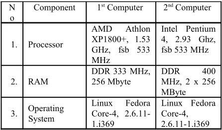
Specification of PC which used in this research is summarized at Table 2. Computer that used must have USB version 2.0 port to support connection with USRP board. Programming language used Phyton and a few block functions written in C++.
Tabel 2. Computer spesifications that used in this research
N
System performance can be measured using one of the parameter which was often used in QoS, that is:
BER < 10-3
, PLR or PER < 10-2
, spread delay < 100 ms, and Gos > 95% [4].
IV. IMPLEMENTATIONAND TEST RESULT
DQPSK modulator and demodulator described previously are implemented in SDR platform using PC and USRP board that commonly used in SDR experiment from GNURadio. The Board is a front side of SDR system and has functions to execute digitalization function (ADC-DAC) and filter channelization process. The digital signal processing used personal computer with USB port as a link between USRP and PC. Operating system used Linux with python programming language to develop the application. All software used for digital signal processing was open source from GNU Radio.
Fig. 6. Spectrum DQPSK signal
This experiment would observe the performance of digital communication based on SDR system using USRP board with DQPSK modulation scheme.The transmission channel of coaxial cable RG58 was used to connect transmitter and receiver because of limitation of Basic TX output power. The experiment was carried out to observe Packet Error Rate (PER) stated by the percentage of exactly accepted packet toward variation of Eb/No, bit rate, carrier frequency, roll-off factor, gain, and also payload size.
Fig. 6 shows the spectrum of DQPSK signal which has 15 MHz carrier frequency, bit rate 256 kbps, and roll-off factor 0.35. The result of observation is shown in Fig. 7 up to Fig. 12.
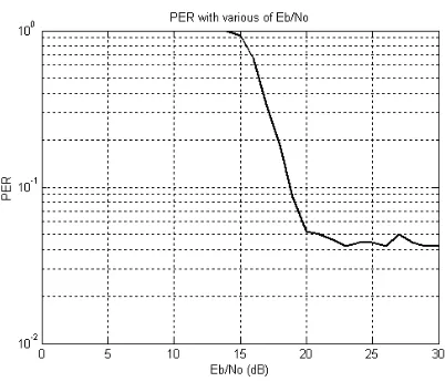
Fig. 7. The effect of Eb/No on PER
Fig. 7 shows the graph between variation of Eb/No concerning the PER value. Referred to the graph perceived, greater value of Eb/No hence smaller PER will be obtained. PER value will remain low for the value of Eb/No higher than 20 dB.
Fig. 8. The effect of carrier frequency on PER
Fig. 9. The effect of bit rate on PER
tried is 44 MHz, and beyond that frequency cannot be handled by USRP using existing Basic TX. Referred to the graph, lowest PER value can be obtained if fC > 0.3
MHz. In another word, the minimum frequency which appropriate for transmitting data with bit-rate 256 kbps is 0.3 MHz.
Fig. 9 shows a graph of bit-rate variation to PER value. Referred to the graph, the optimum bit-rate for the modulation of this DQPSK is 200 kbps. Bit rate greater than 200 kbps will increase the PER value and bit rate from 250 up to 600 kbps produced higher PER value.
Fig. 10 shows a graph of roll-off factor variation value at Nyquist filter to PER value. Referred to the graph, in general can be expressed that bigger roll-off factor value will result smaller PER, and optimum value for roll-off factor to get PER is 0.4. Roll-off factor value for the Nyquist of filter is 0 ≤ α ≤ 1, which value of roll-off equal to 1 referred as roll-off full-cosine which is very useful in signal timing extraction for the process of synchronization. Ever greater value of roll-off factor hence smaller influence of ISI.
Fig. 10. The effect of roll-off factor on PER
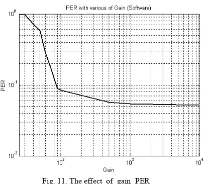
Fig. 11 shows a graph between the variation of gain value and resulted PER value. Referred to the graph, the greater gain will result the smaller PER value. However, for the gain value bigger than 500 PER value do not change the PER value. Hence, the optimum value for gain is 500.
Fig. 11. The effect of gain PER
Fig 12 shows a graph concerning with variation of payload value to PER value. The graph indicated that the bigger transmitted payload value will produce the smaller PER. The maximum data size for this system is 4092 bytes, hence the optimum value for the measure of payload is 4092 bytes.
Fig. 12. The effect of payload size on PER
Referred to all the graphs of this research result, PER value which obtained with variation of Eb/No, carrier frequency, bit rate, roll-off factor, gain, and payload is very low that is closing 10-2
. In spite of comparison with criteria measurement performance where PER < 10-2 not
yet fulfilled. Hence, modulation scheme implementation of DQPSK at platform of SDR use USRP of GNU Radio still require to be completed either software and hardware so that we can get better performance of DQPSK modulation scheme on SDR platform using USRP GNU Radio.
V. CONCLUSION
PER value. Lowest PER Value can be obtained at Eb/No value > 20 dB, optimum bit-rate 200 kbps, carrier frequency bigger than 0,3 MHz, roll-off factor (alpha) is 0.4, optimum gain is 500, and optimum payload value is 4092 byte.
Continuation of this research is software development of SDR to improve the performance and also create application that adept to integration with communications protocol for example TCP/IP.
VI. ACKNOWLEDGMENT
We would like to thank to the Dean of STEI ITB and the chief of PPTIK STEI ITB who have given opportunity also donation in order to accomplish this research. This paper is a part of the current research which has been conducting about SDR platform development, and it is using ITB Research fund year 2007 No : 0047/K01.03.2/PL2.1.5/I/2007. We also thank to all people who contribute to this research.
REFERENCES
[1] Z. Chen., “Performance analysis of channel estimation and adaptive equalization in slow fading channel,” [On-line], Available at http://www.wu.ece.ufl.edu/projects/channelEstima-tion/full_files.zip.
[2] S. Haykin, “Communication System,” 4th ed. New York: John Wiley & Sons, Inc, pp. 362-365.
[3] H. Harada, R. Prasad, Simulation and Software Radio for Mobile Communications. Boston: Artech House, 2002, pp. 75-76. [4] J. Mitola III, Software Radio Architecture. Object-Oriented