Coulson & Richardson’s
CHEMICAL ENGINEERING
Chemical Engineering, Volume 1, Sixth edition Fluid Flow, Heat Transfer and Mass Transfer J. M. Coulson and J. F. Richardson
with J. R. Backhurst and J. H. Harker
Chemical Engineering, Volume 2, Fifth edition Particle Technology and Separation Processes J. F. Richardson and J. H. Harker
with J. R. Backhurst
Chemical Engineering, Volume 3, Third edition Chemical & Biochemical Reactors & Process Control Edited by J. F. Richardson and D. G. Peacock
Chemical Engineering, Second edition Solutions to the Problems in Volume 1
J. R. Backhurst and J. H. Harker with J. F. Richardson
Chemical Engineering, Solutions to the Problems in Volumes 2 and 3
J. R. Backhurst and J. H. Harker with J. F. Richardson
Chemical Engineering, Volume 6, Fourth edition Chemical Engineering Design
Coulson & Richardson’s
CHEMICAL ENGINEERING
VOLUME 6
FOURTH EDITION
Chemical Engineering Design
R. K. SINNOTT
Linacre House, Jordan Hill, Oxford OX2 8DP 30 Corporate Drive, MA 01803
First published 1983 Second edition 1993
Reprinted with corrections 1994 Reprinted with revisions 1996 Third edition 1999
Reprinted 2001, 2003 Fourth edition 2005
Copyright1993, 1996, 1999, 2005 R. K. Sinnott. All rights reserved The right of R. K. Sinnott to be identified as the author of this work has been asserted in accordance with the Copyright, Designs and Patents Act 1988
No part of this publication may be reproduced in any material form (including photocopying or storing in any medium by electronic means and whether or not transiently or incidentally to some other use of this publication) without the written permission of the copyright holder except in accordance with the provisions of the Copyright, Designs and Patents Act 1988 or under the terms of a licence issued by the Copyright Licensing Agency Ltd, 90 Tottenham Court Road, London, England W1T 4LP. Applications for the copyright holder’s written permission to reproduce any part of this publication should be addressed to the publisher
Permissions may be sought directly from Elsevier’s Science & Technology Rights Department in Oxford, UK: phone: (C44) (0)1865 843830; fax: (C44) (0)1865 853333; e-mail: [email protected]. You may also complete your request on-line via the Elsevier homepage (http://www.elsevier.com), by selecting ‘Customer Support’ and then ‘Obtaining Permissions’
British Library Cataloguing in Publication Data
A catalogue record for this book is available from the British Library Library of Congress Cataloguing in Publication Data
A catalogue record for this book is available from the Library of Congress ISBN 0 7506 6538 6
Contents
PREFACE TOFOURTHEDITION xvii
PREFACE TOTHIRDEDITION xx
PREFACE TOSECONDEDITION xxi
PREFACE TOFIRSTEDITION xxiii
SERIESEDITOR’SPREFACE xxiv
ACKNOWLEDGEMENT xxv
1 Introduction to Design 1
1.1 Introduction 1
1.2 Nature of design 1
1.2.1 The design objective (the need) 3
1.2.2 Data collection 3
1.2.3 Generation of possible design solutions 3
1.2.4 Selection 4
1.3 The anatomy of a chemical manufacturing process 5
1.3.1 Continuous and batch processes 7
1.4 The organisation of a chemical engineering project 7
1.5 Project documentation 10
1.6 Codes and standards 12
1.7 Factors of safety (design factors) 13
1.8 Systems of units 14
1.9 Degrees of freedom and design variables. The mathematical representation
of the design problem 15
1.9.1 Information flow and design variables 15
1.9.2 Selection of design variables 19
1.9.3 Information flow and the structure of design problems 20
1.10 Optimisation 24
1.10.1 General procedure 25
1.10.2 Simple models 25
1.10.3 Multiple variable problems 27
1.10.4 Linear programming 29
1.10.5 Dynamic programming 29
1.10.6 Optimisation of batch and semicontinuous processes 29
1.11 References 30
1.12 Nomenclature 31
1.13 Problems 32
2 Fundamentals of Material Balances 34
2.1 Introduction 34
2.2 The equivalence of mass and energy 34
2.3 Conservation of mass 34
2.4 Units used to express compositions 35
2.5 Stoichiometry 36
2.6 Choice of system boundary 37
2.7 Choice of basis for calculations 40
2.8 Number of independent components 40
2.9 Constraints on flows and compositions 41
2.10 General algebraic method 42
2.11 Tie components 44
2.12 Excess reagent 46
2.13 Conversion and yield 47
2.14 Recycle processes 50
2.15 Purge 52
2.16 By-pass 53
2.17 Unsteady-state calculations 54
2.18 General procedure for material-balance problems 56
2.19 References (Further Reading) 57
2.20 Nomenclature 57
2.21 Problems 57
3 Fundamentals of Energy Balances (and Energy Utilisation) 60
3.1 Introduction 60
3.2 Conservation of energy 60
3.3 Forms of energy (per unit mass of material) 61
3.3.1 Potential energy 61
3.4 The energy balance 62
3.5 Calculation of specific enthalpy 67
3.6 Mean heat capacities 68
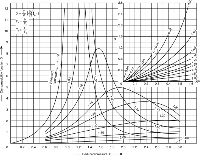
3.7 The effect of pressure on heat capacity 70
3.8 Enthalpy of mixtures 71
3.8.1 Integral heats of solution 72
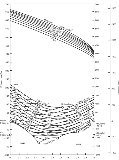
3.9 Enthalpy-concentration diagrams 73
3.10 Heats of reaction 75
3.10.1 Effect of pressure on heats of reaction 77
3.11 Standard heats of formation 79
3.12 Heats of combustion 80
3.13 Compression and expansion of gases 81
3.13.1 Mollier diagrams 82
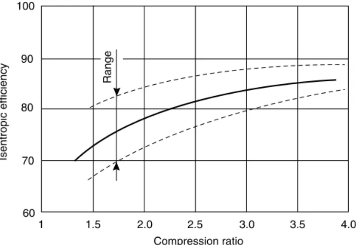
3.13.2 Polytropic compression and expansion 84
3.13.3 Multistage compressors 90
3.13.4 Electrical drives 93
3.14 Energy balance calculations 93
3.15 Unsteady state energy balances 99
3.16 Energy recovery 101
3.16.6 High-pressure process streams 107
3.16.7 Heat pumps 110
3.17 Process integration and pinch technology 111
3.17.1 Pinch technology 111
3.17.2 The problem table method 115
3.17.3 The heat exchanger network 117
3.17.4 Minimum number of exchangers 121
3.17.6 Multiple pinches and multiple utilities 124 3.17.7 Process integration: integration of other process operations 124
3.18 References 127
4.2.3 Presentation of stream flow-rates 134
4.2.4 Information to be included 135
4.2.5 Layout 139
4.2.6 Precision of data 139
4.2.7 Basis of the calculation 140
4.2.8 Batch processes 140
4.2.9 Services (utilities) 140
4.2.10 Equipment identification 140
4.2.11 Computer aided drafting 140
4.3 Manual flow-sheet calculations 141
4.3.1 Basis for the flow-sheet calculations 142
4.3.2 Flow-sheet calculations on individual units 143
4.4 Computer-aided flow-sheeting 168
4.5 Full steady-state simulation programs 168
4.5.1 Information flow diagrams 171
4.6 Manual calculations with recycle streams 172
4.6.1 The split-fraction concept 172
4.6.2 Illustration of the method 176
4.6.3 Guide rules for estimating split-fraction coefficients 185
4.7 References 187
4.8 Nomenclature 188
4.9 Problems 188
5 Piping and Instrumentation 194
5.1 Introduction 194
5.2 The P and I diagram 194
5.2.1 Symbols and layout 195
5.2.2 Basic symbols 195
5.3 Valve selection 197
5.4 Pumps 199
5.4.1 Pump selection 199
5.4.2 Pressure drop in pipelines 201
5.4.3 Power requirements for pumping liquids 206
5.4.4 Characteristic curves for centrifugal pumps 208
5.4.5 System curve (operating line) 210
5.4.6 Net positive suction head (NPSH) 212
5.4.7 Pump and other shaft seals 213
5.5 Mechanical design of piping systems 216
5.5.1 Wall thickness: pipe schedule 216
5.5.2 Pipe supports 217
5.5.3 Pipe fittings 217
5.5.4 Pipe stressing 217
5.5.5 Layout and design 218
5.6 Pipe size selection 218
5.7 Control and instrumentation 227
5.7.1 Instruments 227
5.7.2 Instrumentation and control objectives 227
5.8 Typical control systems 229
5.8.7 Distillation column control 231
5.8.8 Reactor control 233
5.9 Alarms and safety trips, and interlocks 235
5.10 Computers and microprocessors in process control 236
5.11 References 238
5.12 Nomenclature 239
5.13 Problems 240
6 Costing and Project Evaluation 243
6.1 Introduction 243
6.2 Accuracy and purpose of capital cost estimates 243
6.3 Fixed and working capital 244
6.4 Cost escalation (inflation) 245
6.5 Rapid capital cost estimating methods 247
6.5.1 Historical costs 247
6.5.2 Step counting methods 249
6.6 The factorial method of cost estimation 250
6.6.1 Lang factors 251
6.6.2 Detailed factorial estimates 251
6.7 Estimation of purchased equipment costs 253
6.8 Summary of the factorial method 260
6.9 Operating costs 260
6.9.1 Estimation of operating costs 261
6.10 Economic evaluation of projects 270
6.10.1 Cash flow and cash-flow diagrams 270
6.10.2 Tax and depreciation 272
6.10.3 Discounted cash flow (time value of money) 272
6.10.4 Rate of return calculations 273
6.10.5 Discounted cash-flow rate of return (DCFRR) 273
6.10.6 Pay-back time 274
6.10.7 Allowing for inflation 274
6.10.8 Sensitivity analysis 274
6.10.9 Summary 275
6.11 Computer methods for costing and project evaluation 278
6.12 References 279
6.13 Nomenclature 279
6.14 Problems 280
7 Materials of Construction 284
7.1 Introduction 284
7.3.7 Effect of temperature on the mechanical properties 287
7.4 Corrosion resistance 287
7.4.1 Uniform corrosion 288
7.4.3 Pitting 290
7.4.4 Intergranular corrosion 290
7.4.5 Effect of stress 290
7.4.6 Erosion-corrosion 291
7.4.7 High-temperature oxidation 291
7.4.8 Hydrogen embrittlement 292
7.5 Selection for corrosion resistance 292
7.6 Material costs 293
7.7 Contamination 294
7.7.1 Surface finish 295
7.8 Commonly used materials of construction 295
7.8.1 Iron and steel 295
7.8.2 Stainless steel 296
7.8.3 Nickel 298
7.8.4 Monel 299
7.8.5 Inconel 299
7.8.6 The Hastelloys 299
7.8.7 Copper and copper alloys 299
7.8.8 Aluminium and its alloys 299
7.8.9 Lead 300
7.9 Plastics as materials of construction for chemical plant 301
7.9.1 Poly-vinyl chloride (PVC) 302
7.9.2 Polyolefines 302
7.9.3 Polytetrafluroethylene (PTFE) 302
7.9.4 Polyvinylidene fluoride (PVDF) 302
7.9.5 Glass-fibre reinforced plastics (GRP) 302
7.9.6 Rubber 303
7.10 Ceramic materials (silicate materials) 303
7.10.1 Glass 304
7.10.2 Stoneware 304
7.10.3 Acid-resistant bricks and tiles 304
7.10.4 Refractory materials (refractories) 304
7.11 Carbon 305
7.12 Protective coatings 305
7.13 Design for corrosion resistance 305
7.14 References 305
7.15 Nomenclature 307
7.16 Problems 307
8 Design Information and Data 309
8.1 Introduction 309
8.2 Sources of information on manufacturing processes 309
8.3 General sources of physical properties 311
8.4 Accuracy required of engineering data 312
8.5 Prediction of physical properties 313
8.6 Density 314
8.6.1 Liquids 314
8.6.2 Gas and vapour density (specific volume) 315
8.8.3 Gases 321
8.8.4 Mixtures 322
8.9 Specific heat capacity 322
8.9.1 Solids and liquids 322
8.9.2 Gases 325
8.10 Enthalpy of vaporisation (latent heat) 328
8.10.1 Mixtures 329
8.11 Vapour pressure 330
8.12 Diffusion coefficients (diffusivities) 331
8.12.1 Gases 331
8.12.2 Liquids 333
8.13 Surface tension 335
8.13.1 Mixtures 335
8.14 Critical constants 336
8.15 Enthalpy of reaction and enthalpy of formation 339
8.16 Phase equilibrium data 339
8.16.1 Experimental data 339
8.16.2 Phase equilibria 339
8.16.3 Equations of state 341
8.16.4 Correlations for liquid phase activity coefficients 342 8.16.5 Prediction of vapour-liquid equilibria 346
8.16.6 K-values for hydrocarbons 348
8.16.7 Sour-water systems (Sour) 348
8.16.8 Vapour-liquid equilibria at high pressures 348
8.16.9 Liquid-liquid equilibria 348
8.16.10 Choice of phase equilibria for design calculations 350
8.16.11 Gas solubilities 351
8.16.12 Use of equations of state to estimate specific enthalpy and density 353
8.17 References 353
8.18 Nomenclature 357
8.19 Problems 358
9 Safety and Loss Prevention 360
9.1 Introduction 360
9.2 Intrinsic and extrinsic safety 361
9.3 The hazards 361
9.3.1 Toxicity 361
9.3.2 Flammability 363
9.3.3 Explosions 365
9.3.4 Sources of ignition 366
9.3.5 Ionising radiation 368
9.3.6 Pressure 368
9.3.7 Temperature deviations 369
9.3.8 Noise 370
9.4 Dow fire and explosion index 371
9.4.1 Calculation of the Dow F & EI 371
9.4.2 Potential loss 375
9.4.3 Basic preventative and protective measures 377 9.4.4 Mond fire, explosion, and toxicity index 378
9.4.5 Summary 379
9.5 Hazard and operability studies 381
9.5.1 Basic principles 382
9.5.2 Explanation of guide words 383
9.5.3 Procedure 384
9.6 Hazard analysis 389
9.7 Acceptable risk and safety priorities 390
9.8 Safety check lists 392
9.9 Major hazards 394
9.10 References 396
9.11 Problems 398
10 Equipment Selection, Specification and Design 400
10.1 Introduction 400
10.2 Separation processes 401
10.3 Solid-solid separations 401
10.3.1 Screening (sieving) 401
10.3.2 Liquid-solid cyclones 404
10.3.3 Hydroseparators and sizers (classifiers) 405
10.3.4 Hydraulic jigs 405
10.3.5 Tables 405
10.3.6 Classifying centrifuges 406
10.3.7 Dense-medium separators (sink and float processes) 406 10.3.8 Flotation separators (froth-flotation) 407
10.3.9 Magnetic separators 407
10.3.10 Electrostatic separators 408
10.4 Liquid-solid (solid-liquid) separators 408
10.4.1 Thickeners and clarifiers 408
10.4.2 Filtration 409
10.4.3 Centrifuges 415
10.4.4 Hydrocyclones (liquid-cyclones) 422
10.4.5 Pressing (expression) 426
10.4.6 Solids drying 426
10.5 Separation of dissolved solids 434
10.5.1 Evaporators 434
10.7 Separation of dissolved liquids 446
10.7.1 Solvent extraction and leaching 447
10.8 Gas-solids separations (gas cleaning) 448
10.8.1 Gravity settlers (settling chambers) 448
10.8.2 Impingement separators 448
10.8.3 Centrifugal separators (cyclones) 450
10.8.4 Filters 458
10.8.5 Wet scrubbers (washing) 459
10.8.6 Electrostatic precipitators 459
10.9 Gas liquid separators 460
10.9.1 Settling velocity 461
10.9.2 Vertical separators 461
10.9.3 Horizontal separators 463
10.10 Crushing and grinding (comminution) equipment 465
10.11 Mixing equipment 468
10.11.1 Gas mixing 468
10.11.2 Liquid mixing 468
10.11.3 Solids and pastes 476
10.12 Transport and storage of materials 476
10.12.1 Gases 477
10.12.2 Liquids 479
10.12.3 Solids 481
10.13 Reactors 482
10.13.1 Principal types of reactor 483
10.13.2 Design procedure 486
10.14 References 486
10.15 Nomenclature 490
11 Separation Columns (Distillation, Absorption and Extraction) 493
11.1 Introduction 493
11.2 Continuous distillation: process description 494
11.2.1 Reflux considerations 495
11.2.2 Feed-point location 496
11.2.3 Selection of column pressure 496
11.3 Continuous distillation: basic principles 497
11.3.1 Stage equations 497
11.3.2 Dew points and bubble points 498
11.3.3 Equilibrium flash calculations 499
11.4 Design variables in distillation 501
11.5 Design methods for binary systems 503
11.5.1 Basic equations 503
11.5.2 McCabe-Thiele method 505
11.5.3 Low product concentrations 507
11.5.4 The Smoker equations 512
11.6 Multicomponent distillation: general considerations 515
11.6.1 Key components 516
11.6.2 Number and sequencing of columns 517
11.7 Multicomponent distillation: short-cut methods for stage and reflux requirements 517
11.7.1 Pseudo-binary systems 518
11.7.2 Smith-Brinkley method 522
11.7.3 Empirical correlations 523
11.7.4 Distribution of non-key components (graphical method) 526 11.8 Multicomponent systems: rigorous solution procedures (computer methods) 542
11.8.1 Lewis-Matheson method 543
11.8.2 Thiele-Geddes method 544
11.8.3 Relaxation methods 545
11.8.4 Linear algebra methods 545
11.9 Other distillation systems 546
11.9.1 Batch distillation 546
11.9.2 Steam distillation 546
11.9.3 Reactive distillation 547
11.10 Plate efficiency 547
11.10.1 Prediction of plate efficiency 548
11.10.2 O’Connell’s correlation 550
11.10.3 Van Winkle’s correlation 552
11.10.4 AIChE method 553
11.10.5 Entrainment 556
11.11 Approximate column sizing 557
11.12 Plate contactors 557
11.12.1 Selection of plate type 560
11.12.2 Plate construction 561
11.13 Plate hydraulic design 565
11.13.1 Plate-design procedure 567
11.13.7 Weir liquid crest 572
11.13.8 Weir dimensions 572
11.13.14 Plate pressure drop 575
11.13.15 Downcomer design [back-up] 577
11.14 Packed columns 587
11.14.2 Packed-bed height 593 11.14.3 Prediction of the height of a transfer unit (HTU) 597
11.14.4 Column diameter (capacity) 602
11.14.5 Column internals 609
11.14.6 Wetting rates 616
11.15 Column auxiliaries 616
11.16 Solvent extraction (liquid liquid extraction) 617
11.16.1 Extraction equipment 617
11.16.2 Extractor design 618
11.16.3 Extraction columns 623
11.16.4 Supercritical fluid extraction 624
11.17 References 624
11.18 Nomenclature 627
11.19 Problems 630
12 Heat-transfer Equipment 634
12.1 Introduction 634
12.2 Basic design procedure and theory 635
12.2.1 Heat exchanger analysis: the effectiveness NTU method 636
12.3 Overall heat-transfer coefficient 636
12.4 Fouling factors (dirt factors) 638
12.5 Shell and tube exchangers: construction details 640
12.5.1 Heat-exchanger standards and codes 644
12.5.2 Tubes 645
12.5.3 Shells 647
12.5.4 Tube-sheet layout (tube count) 647
12.5.5 Shell types (passes) 649
12.5.6 Shell and tube designation 649
12.5.7 Baffles 650
12.5.8 Support plates and tie rods 652
12.5.9 Tube sheets (plates) 652
12.5.10 Shell and header nozzles (branches) 653
12.5.11 Flow-induced tube vibrations 653
12.6 Mean temperature difference (temperature driving force) 655 12.7 Shell and tube exchangers: general design considerations 660
12.7.1 Fluid allocation: shell or tubes 660
12.7.2 Shell and tube fluid velocities 660
12.7.3 Stream temperatures 661
12.7.4 Pressure drop 661
12.7.5 Fluid physical properties 661
12.8 Tube-side heat-transfer coefficient and pressure drop (single phase) 662
12.8.1 Heat transfer 662
12.8.2 Tube-side pressure drop 666
12.9 Shell-side heat-transfer and pressure drop (single phase) 669
12.9.1 Flow pattern 669
12.9.2 Design methods 670
12.9.3 Kern’s method 671
12.9.4 Bell’s method 693
12.9.5 Shell and bundle geometry 702
12.9.6 Effect of fouling on pressure drop 705
12.9.7 Pressure-drop limitations 705
12.10 Condensers 709
12.10.1 Heat-transfer fundamentals 710
12.10.2 Condensation outside horizontal tubes 710 12.10.3 Condensation inside and outside vertical tubes 711
12.10.4 Condensation inside horizontal tubes 716
12.10.5 Condensation of steam 717
12.10.6 Mean temperature difference 717
12.10.8 Condensation of mixtures 719
12.10.9 Pressure drop in condensers 723
12.11 Reboilers and vaporisers 728
12.11.1 Boiling heat-transfer fundamentals 731
12.11.2 Pool boiling 732
12.11.3 Convective boiling 735
12.11.4 Design of forced-circulation reboilers 740
12.11.5 Design of thermosyphon reboilers 741
12.11.6 Design of kettle reboilers 750
12.12 Plate heat exchangers 756
12.12.1 Gasketed plate heat exchangers 756
12.12.2 Welded plate 764
12.12.3 Plate-fin 764
12.12.4 Spiral heat exchangers 765
12.13 Direct-contact heat exchangers 766
12.14 Finned tubes 767
12.15 Double-pipe heat exchangers 768
12.16 Air-cooled exchangers 769
12.17 Fired heaters (furnaces and boilers) 769
12.17.1 Basic construction 770
12.17.2 Design 771
12.17.3 Heat transfer 772
12.17.4 Pressure drop 774
12.17.5 Process-side heat transfer and pressure drop 774
12.17.6 Stack design 774
12.17.7 Thermal efficiency 775
12.18 Heat transfer to vessels 775
12.18.1 Jacketed vessels 775
13 Mechanical Design of Process Equipment 794
13.1 Introduction 794
13.1.1 Classification of pressure vessels 795
13.2 Pressure vessel codes and standards 795
13.3 Fundamental principles and equations 796
13.3.1 Principal stresses 796
13.3.2 Theories of failure 797
13.3.3 Elastic stability 798
13.3.4 Membrane stresses in shells of revolution 798
13.3.5 Flat plates 805
13.3.6 Dilation of vessels 809
13.3.7 Secondary stresses 809
13.4 General design considerations: pressure vessels 810
13.4.1 Design pressure 810
13.4.2 Design temperature 810
13.4.3 Materials 811
13.4.4 Design stress (nominal design strength) 811 13.4.5 Welded joint efficiency, and construction categories 812
13.4.6 Corrosion allowance 813
13.4.7 Design loads 814
13.4.8 Minimum practical wall thickness 814
13.5 The design of thin-walled vessels under internal pressure 815
13.5.1 Cylinders and spherical shells 815
13.5.2 Heads and closures 815
13.5.3 Design of flat ends 817
13.5.4 Design of domed ends 818
13.6 Compensation for openings and branches 822 13.7 Design of vessels subject to external pressure 825
13.7.1 Cylindrical shells 825
13.7.2 Design of stiffness rings 828
13.7.3 Vessel heads 829
13.8 Design of vessels subject to combined loading 831
13.8.1 Weight loads 835
13.8.2 Wind loads (tall vessels) 837
13.8.3 Earthquake loading 839
13.8.4 Eccentric loads (tall vessels) 840
13.8.5 Torque 841
13.9 Vessel supports 844
13.9.1 Saddle supports 844
13.9.2 Skirt supports 848
13.9.3 Bracket supports 856
13.10 Bolted flanged joints 858
13.10.1 Types of flange, and selection 858
13.10.2 Gaskets 859
13.10.3 Flange faces 861
13.10.4 Flange design 862
13.10.5 Standard flanges 865
13.11 Heat-exchanger tube-plates 867
13.12 Welded joint design 869
13.13 Fatigue assessment of vessels 872
13.14 Pressure tests 872
13.15 High-pressure vessels 873
13.15.1 Fundamental equations 873
13.15.2 Compound vessels 877
13.15.3 Autofrettage 878
13.16 Liquid storage tanks 879
13.17 Mechanical design of centrifuges 879
13.17.1 Centrifugal pressure 879
13.17.2 Bowl and spindle motion: critical speed 881
13.18 References 883
13.19 Nomenclature 885
13.20 Problems 889
14 General Site Considerations 892
14.1 Introduction 892
14.2 Plant location and site selection 892
14.3 Site layout 894
14.4 Plant layout 896
14.4.1 Techniques used in site and plant layout 897
14.5 Utilities 900
APPENDIXA: GRAPHICALSYMBOLS FORPIPINGSYSTEMS ANDPLANT 908
APPENDIXB: CORROSIONCHART 917
APPENDIXC: PHYSICALPROPERTYDATABANK 937
APPENDIXE: STANDARDFLANGES 960
APPENDIXF: DESIGNPROJECTS 965
APPENDIXG: EQUIPMENTSPECIFICATION(DATA) SHEETS 990
APPENDIXH: TYPICALSHELL ANDTUBEHEATEXCHANGERTUBE-SHEETLAYOUTS 1002
AUTHORINDEX 1007
CHAPTER 1
Introduction to Design
1.1. INTRODUCTION
This chapter is an introduction to the nature and methodology of the design process, and its application to the design of chemical manufacturing processes.
1.2. NATURE OF DESIGN
This section is a general, somewhat philosophical, discussion of the design process; how a designer works. The subject of this book is chemical engineering design, but the method-ology of design described in this section applies equally to other branches of engineering design.
Design is a creative activity, and as such can be one of the most rewarding and satisfying activities undertaken by an engineer. It is the synthesis, the putting together, of ideas to achieve a desired purpose. The design does not exist at the commencement of the project. The designer starts with a specific objective in mind, a need, and by developing and evaluating possible designs, arrives at what he considers the best way of achieving that objective; be it a better chair, a new bridge, or for the chemical engineer, a new chemical product or a stage in the design of a production process.
When considering possible ways of achieving the objective the designer will be constrained by many factors, which will narrow down the number of possible designs; but, there will rarely be just one possible solution to the problem, just one design. Several alternative ways of meeting the objective will normally be possible, even several best designs, depending on the nature of the constraints.
These constraints on the possible solutions to a problem in design arise in many ways. Some constraints will be fixed, invariable, such as those that arise from physical laws, government regulations, and standards. Others will be less rigid, and will be capable of relaxation by the designer as part of his general strategy in seeking the best design. The constraints that are outside the designer’s influence can be termed the external constraints. These set the outer boundary of possible designs; as shown in Figure 1.1. Within this boundary there will be a number of plausible designs bounded by the other constraints, the internal constraints, over which the designer has some control; such as, choice of process, choice of process conditions, materials, equipment.
Economic considerations are obviously a major constraint on any engineering design: plants must make a profit.
Time will also be a constraint. The time available for completion of a design will usually limit the number of alternative designs that can be considered.
Plausible designs
Government controls
Economic constraints
Safety regulations
Resources
Physical laws
Standards and codes
Personnel
Materials
Process conditions Choice of
process
Methods
Time
“External” constraints “Internal” constraints Region of all designs
Possible designs
Figure 1.1. Design constraints Objective
(design specification)
Collection of data, physical properties design
methods
Generation of possible designs
Selection and evaluation (optimisation)
Final design
Figure 1.2. The design process
The stages in the development of a design, from the initial identification of the objective to the final design, are shown diagrammatically in Figure 1.2. Each stage is discussed in the following sections.
1.2.1. The design objective (the need)
Chaddock (1975) defined design as, the conversion of an ill-defined requirement into a satisfied customer.
The designer is creating a design for an article, or a manufacturing process, to fulfil a particular need. In the design of a chemical process, the need is the public need for the product, the commercial opportunity, as foreseen by the sales and marketing organisation. Within this overall objective the designer will recognise sub-objectives; the requirements of the various units that make up the overall process.
Before starting work the designer should obtain as complete, and as unambiguous, a statement of the requirements as possible. If the requirement (need) arises from outside the design group, from a client or from another department, then he will have to elucidate the real requirements through discussion. It is important to distinguish between the real needs and the wants. The wants are those parts of the initial specification that may be thought desirable, but which can be relaxed if required as the design develops. For example, a particular product specification may be considered desirable by the sales department, but may be difficult and costly to obtain, and some relaxation of the specification may be possible, producing a saleable but cheaper product. Whenever he is in a position to do so, the designer should always question the design requirements (the project and equipment specifications) and keep them under review as the design progresses.
Where he writes specifications for others, such as for the mechanical design or purchase of a piece of equipment, he should be aware of the restrictions (constraints) he is placing on other designers. A tight, well-thought-out, comprehensive, specification of the require-ments defines the external constraints within which the other designers must work.
1.2.2. Data collection
To proceed with a design, the designer must first assemble all the relevant facts and data required. For process design this will include information on possible processes, equipment performance, and physical property data. This stage can be one of the most time consuming, and frustrating, aspects of design. Sources of process information and physical properties are reviewed in Chapter 8.
Many design organisations will prepare a basic data manual, containing all the process “know-how” on which the design is to be based. Most organisations will have design manuals covering preferred methods and data for the more frequently used, routine, design procedures.
The national standards are also sources of design methods and data; they are also design constraints.
The constraints, particularly the external constraints, should be identified early in the design process.
1.2.3. Generation of possible design solutions
It is doubtful if any design is entirely novel. The antecedence of most designs can usually be easily traced. The first motor cars were clearly horse-drawn carriages without the horse; and the development of the design of the modern car can be traced step by step from these early prototypes. In the chemical industry, modern distillation processes have developed from the ancient stills used for rectification of spirits; and the packed columns used for gas absorption have developed from primitive, brushwood-packed towers. So, it is not often that a process designer is faced with the task of producing a design for a completely novel process or piece of equipment.
The experienced engineer will wisely prefer the tried and tested methods, rather than possibly more exciting but untried novel designs. The work required to develop new processes, and the cost, is usually underestimated. Progress is made more surely in small steps. However, whenever innovation is wanted, previous experience, through prejudice, can inhibit the generation and acceptance of new ideas; the “not invented here” syndrome. The amount of work, and the way it is tackled, will depend on the degree of novelty in a design project.
Chemical engineering projects can be divided into three types, depending on the novelty involved:
1. Modifications, and additions, to existing plant; usually carried out by the plant design group.
2. New production capacity to meet growing sales demand, and the sale of established processes by contractors. Repetition of existing designs, with only minor design changes.
3. New processes, developed from laboratory research, through pilot plant, to a commercial process. Even here, most of the unit operations and process equipment will use established designs.
The first step in devising a new process design will be to sketch out a rough block diagram showing the main stages in the process; and to list the primary function (objective) and the major constraints for each stage. Experience should then indicate what types of unit operations and equipment should be considered.
Jones (1970) discusses the methodology of design, and reviews some of the special techniques, such as brainstorming sessions and synectics, that have been developed to help generate ideas for solving intractable problems. A good general reference on the art of problem solving is the classical work by Polya (1957); see also Chittenden (1987). Some techniques for problem solving in the Chemical Industry are covered in a short text by Casey and Frazer (1984).
The generation of ideas for possible solutions to a design problem cannot be separated from the selection stage of the design process; some ideas will be rejected as impractical as soon as they are conceived.
1.2.4. Selection
The selection process can be considered to go through the following stages:
Possible designs (credible) within the external constraints. Plausible designs (feasible) within the internal constraints.
Probable designs likely candidates.
Best design (optimum) judged the best solution to the problem.
The selection process will become more detailed and more refined as the design progresses from the area of possible to the area of probable solutions. In the early stages a coarse screening based on common sense, engineering judgement, and rough costings will usually suffice. For example, it would not take many minutes to narrow down the choice of raw materials for the manufacture of ammonia from the possible candidates of, say, wood, peat, coal, natural gas, and oil, to a choice of between gas and oil, but a more detailed study would be needed to choose between oil and gas. To select the best design from the probable designs, detailed design work and costing will usually be necessary. However, where the performance of candidate designs is likely to be close the cost of this further refinement, in time and money, may not be worthwhile, particularly as there will usually be some uncertainty in the accuracy of the estimates.
The mathematical techniques that have been developed to assist in the optimisation of designs, and plant performance, are discussed briefly in Section 1.10.
Rudd and Watson (1968) and Wells (1973) describe formal techniques for the prelim-inary screening of alternative designs.
1.3. THE ANATOMY OF A CHEMICAL MANUFACTURING
PROCESS
The basic components of a typical chemical process are shown in Figure 1.3, in which each block represents a stage in the overall process for producing a product from the raw materials. Figure 1.3 represents a generalised process; not all the stages will be needed for any particular process, and the complexity of each stage will depend on the nature of the process. Chemical engineering design is concerned with the selection and arrangement of the stages, and the selection, specification and design of the equipment required to perform the stage functions.
Stage 1 Stage 2 Stage 3 Stage 4 Stage 5 Stage 6 Figure 1.3. Anatomy of a chemical process
Stage 1. Raw material storage
have to be made to hold several days, or weeks, storage to smooth out fluctuations and interruptions in supply. Even when the materials come from an adjacent plant some provision is usually made to hold a few hours, or even days, supply to decouple the processes. The storage required will depend on the nature of the raw materials, the method of delivery, and what assurance can be placed on the continuity of supply. If materials are delivered by ship (tanker or bulk carrier) several weeks stocks may be necessary; whereas if they are received by road or rail, in smaller lots, less storage will be needed.
Stage 2. Feed preparation
Some purification, and preparation, of the raw materials will usually be necessary before they are sufficiently pure, or in the right form, to be fed to the reaction stage. For example, acetylene generated by the carbide process contains arsenical and sulphur compounds, and other impurities, which must be removed by scrubbing with concentrated sulphuric acid (or other processes) before it is sufficiently pure for reaction with hydrochloric acid to produce dichloroethane. Liquid feeds will need to be vaporised before being fed to gas-phase reactors, and solids may need crushing, grinding and screening.
Stage 3. Reactor
The reaction stage is the heart of a chemical manufacturing process. In the reactor the raw materials are brought together under conditions that promote the production of the desired product; invariably, by-products and unwanted compounds (impurities) will also be formed.
Stage 4. Product separation
In this first stage after the reactor the products and by-products are separated from any unreacted material. If in sufficient quantity, the unreacted material will be recycled to the reactor. They may be returned directly to the reactor, or to the feed purification and preparation stage. The by-products may also be separated from the products at this stage.
Stage 5. Purification
Before sale, the main product will usually need purification to meet the product specifi-cation. If produced in economic quantities, the by-products may also be purified for sale.
Stage 6. Product storage
Some inventory of finished product must be held to match production with sales. Provision for product packaging and transport will also be needed, depending on the nature of the product. Liquids will normally be dispatched in drums and in bulk tankers (road, rail and sea), solids in sacks, cartons or bales.
The stock held will depend on the nature of the product and the market.
Ancillary processes
water, compressed air, steam. Facilities will also be needed for maintenance, firefighting, offices and other accommodation, and laboratories; see Chapter 14.
1.3.1. Continuous and batch processes
Continuous processes are designed to operate 24 hours a day, 7 days a week, throughout the year. Some down time will be allowed for maintenance and, for some processes, catalyst regeneration. The plant attainment; that is, the percentage of the available hours in a year that the plant operates, will usually be 90 to 95%.
Attainment %D hours operated
8760 ð100
Batch processes are designed to operate intermittently. Some, or all, the process units being frequently shut down and started up.
Continuous processes will usually be more economical for large scale production. Batch processes are used where some flexibility is wanted in production rate or product speci-fication.
Choice of continuous versus batch production
The choice between batch or continuous operation will not be clear cut, but the following rules can be used as a guide.
Continuous
1. Production rate greater than 5ð106 kg/h
2. Single product 3. No severe fouling 4. Good catalyst life 5. Proven processes design 6. Established market
Batch
1. Production rate less than 5ð106 kg/h
2. A range of products or product specifications 3. Severe fouling
4. Short catalyst life 5. New product 6. Uncertain design
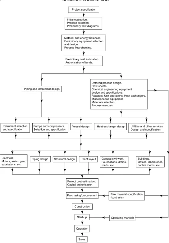
1.4. THE ORGANISATION OF A CHEMICAL ENGINEERING
PROJECT
The design work required in the engineering of a chemical manufacturing process can be divided into two broad phases.
Project specification
Initial evaluation. Process selection. Preliminary flow diagrams.
Detailed process design. Flow-sheets.
Chemical engineering equipment design and specifications.
Reactors, Unit operations, Heat exchangers, Miscellaneous equipment.
Materials selection. Process manuals Material and energy balances. Preliminary equipment selection and design.
Process flow-sheeting.
Preliminary cost estimation. Authorisation of funds.
Piping and instrument design
Instrument selection and specification
Pumps and compressors. Selection and specification
Vessel design Heat exchanger design Utilities and other services. Design and specification
Electrical, Motors, switch gear, substations, etc.
Piping design Structural design Plant layout General civil work. Foundations, drains, roads, etc.
Buildings. Offices, laboratories, control rooms, etc.
Project cost estimation. Capital authorisation
Purchasing/procurement Raw material specification. (contracts)
Construction
Start-up Operating manuals
Operation
Sales
specification and chemical engineering design of equipment. In a typical organisation, this phase is the responsibility of the Process Design Group, and the work will be mainly done by chemical engineers. The process design group may also be responsible for the preparation of the piping and instrumentation diagrams.
Phase 2. The detailed mechanical design of equipment; the structural, civil and electrical design; and the specification and design of the ancillary services. These activities will be the responsibility of specialist design groups, having expertise in the whole range of engineering disciplines.
Other specialist groups will be responsible for cost estimation, and the purchase and procurement of equipment and materials.
The sequence of steps in the design, construction and start-up of a typical chemical process plant is shown diagrammatically in Figure 1.4 and the organisation of a typical project group in Figure 1.5. Each step in the design process will not be as neatly separated from the others as is indicated in Figure 1.4; nor will the sequence of events be as clearly defined. There will be a constant interchange of information between the various design sections as the design develops, but it is clear that some steps in a design must be largely completed before others can be started.
A project manager, often a chemical engineer by training, is usually responsible for the co-ordination of the project, as shown in Figure 1.5.
Specialist design sections
The organisation of chemical process design is discussed in more detail by Rase and Barrow (1964) and Baasel (1974).
Some of the larger chemical manufacturing companies have their own project design organisations and carry out the whole project design and engineering, and possibly construction, within their own organisation. More usually the design and construction, and possibly assistance with start-up, is entrusted to one of the international contracting firms. The operating company will often provide the “know-how” for the process, and will work closely with the contractor throughout all stages of the project.
1.5. PROJECT DOCUMENTATION
As shown in Figure 1.5 and described in Section 1.4, the design and engineering of a chemical process requires the operation of many specialist groups. Effective co-operation depends on effective communications, and all design organisations have formal procedures for handling project information and documentation. The project documen-tation will include:
1. General correspondence within the design group and with: government departments
equipment vendors site personnel the client
2. Calculation sheets design calculations
costing
computer print-out
3. Drawings flow-sheets
piping and instrumentation diagrams layout diagrams
plot/site plans equipment details piping diagrams architectural drawings design sketches
4. Specification sheets for equipment, such as:
heat exchangers pumps
5. Purchase orders quotations
invoices
All documents should be assigned a code number for easy cross referencing, filing and retrieval.
Calculation sheets
sheets the basis of the calculations, and any assumptions and approximations made, in sufficient detail for the methods, as well as the arithmetic, to be checked. Design calcula-tions are normally set out on standard sheets. The heading at the top of each sheet should include: the project title and identification number and, most importantly, the signature (or initials) of the person who checked the calculation.
Drawings
All project drawings are normally drawn on specially printed sheets, with the company name; project title and number; drawing title and identification number; draughtsman’s name and person checking the drawing; clearly set out in a box in the bottom right-hand corner. Provision should also be made for noting on the drawing all modifications to the initial issue.
Drawings should conform to accepted drawing conventions, preferably those laid down by the national standards. The symbols used for flow-sheets and piping and instrument diagrams are discussed in Chapter 4. Drawings and sketches are normally made on detail paper (semi-transparent) in pencil, so modifications can be easily made, and prints taken.
In most design offices Computer Aided Design (CAD) methods are now used to produce the drawings required for all the aspects of a project: flow-sheets, piping and instrumen-tation, mechanical and civil work.
Specification sheets
Standard specification sheets are normally used to transmit the information required for the detailed design, or purchase, of equipment items; such as, heat exchangers, pumps, columns.
As well as ensuring that the information is clearly and unambiguously presented, standard specification sheets serve as check lists to ensure that all the information required is included.
Examples of equipment specification sheets are given in Appendix G.
Process manuals
Process manuals are often prepared by the process design group to describe the process and the basis of the design. Together with the flow-sheets, they provide a complete technical description of the process.
Operating manuals
1.6. CODES AND STANDARDS
The need for standardisation arose early in the evolution of the modern engineering industry; Whitworth introduced the first standard screw thread to give a measure of interchangeability between different manufacturers in 1841. Modern engineering standards cover a much wider function than the interchange of parts. In engineering practice they cover:
1. Materials, properties and compositions.
2. Testing procedures for performance, compositions, quality. 3. Preferred sizes; for example, tubes, plates, sections. 4. Design methods, inspection, fabrication.
5. Codes of practice, for plant operation and safety.
The terms STANDARD and CODE are used interchangeably, though CODE should really be reserved for a code of practice covering say, a recommended design or operating procedure; and STANDARD for preferred sizes, compositions, etc.
All of the developed countries, and many of the developing countries, have national standards organisations, responsible for the issue and maintenance of standards for the manufacturing industries, and for the protection of consumers. In the United Kingdom preparation and promulgation of national standards are the responsibility of the British Standards Institution (BSI). The Institution has a secretariat and a number of technical personnel, but the preparation of the standards is largely the responsibility of committees of persons from the appropriate industry, the professional engineering institutions and other interested organisations.
In the United States the government organisation responsible for coordinating infor-mation on standards is the National Bureau of Standards; standards are issued by Federal, State and various commercial organisations. The principal ones of interest to chemical engineers are those issued by the American National Standards Institute (ANSI), the American Petroleum Institute (API), the American Society for Testing Materials (ASTM), and the American Society of Mechanical Engineers (ASME) (pressure vessels). Burklin (1979) gives a comprehensive list of the American codes and standards.
The International Organization for Standardization (ISO) coordinates the publication of international standards.
All the published British standards are listed, and their scope and application described,
in the British Standards Institute Catalogue; which the designer should consult. The
catalogue is available online, go to the BSI group home page, www.bsi-global.com. As well as the various national standards and codes, the larger design organisations will have their own (in-house) standards. Much of the detail in engineering design work is routine and repetitious, and it saves time and money, and ensures a conformity between projects, if standard designs are used whenever practicable.
For the designer, the use of a standardised component size allows for the easy integration of a piece of equipment into the rest of the plant. For example, if a standard range of centrifugal pumps is specified the pump dimensions will be known, and this facilitates the design of the foundations plates, pipe connections and the selection of the drive motors: standard electric motors would be used.
For an operating company, the standardisation of equipment designs and sizes increases interchangeability and reduces the stock of spares that have to be held in maintenance stores.
Though there are clearly considerable advantages to be gained from the use of standards in design, there are also some disadvantages. Standards impose constraints on the designer. The nearest standard size will normally be selected on completing a design calculation (rounding-up) but this will not necessarily be the optimum size; though as the standard size will be cheaper than a special size, it will usually be the best choice from the point of view of initial capital cost. Standard design methods must, of their nature, be historical, and do not necessarily incorporate the latest techniques.
The use of standards in design is illustrated in the discussion of the pressure vessel design standards (codes) in Chapter 13.
1.7. FACTORS OF SAFETY (DESIGN FACTORS)
Design is an inexact art; errors and uncertainties will arise from uncertainties in the design data available and in the approximations necessary in design calculations. To ensure that the design specification is met, factors are included to give a margin of safety in the design; safety in the sense that the equipment will not fail to perform satisfactorily, and that it will operate safely: will not cause a hazard. “Design factor” is a better term to use, as it does not confuse safety and performance factors.
In mechanical and structural design, the magnitude of the design factors used to allow for uncertainties in material properties, design methods, fabrication and operating loads are well established. For example, a factor of around 4 on the tensile strength, or about 2.5 on the 0.1 per cent proof stress, is normally used in general structural design. The selection of design factors in mechanical engineering design is illustrated in the discussion of pressure vessel design in Chapter 13.
Design factors are also applied in process design to give some tolerance in the design. For example, the process stream average flows calculated from material balances are usually increased by a factor, typically 10 per cent, to give some flexibility in process operation. This factor will set the maximum flows for equipment, instrumentation, and piping design. Where design factors are introduced to give some contingency in a process design, they should be agreed within the project organisation, and clearly stated in the project documents (drawings, calculation sheets and manuals). If this is not done, there is a danger that each of the specialist design groups will add its own “factor of safety”; resulting in gross, and unnecessary, over-design.
1.8. SYSTEMS OF UNITS
To be consistent with the other volumes in this series, SI units have been used in this book. However, in practice the design methods, data and standards which the designer will use are often only available in the traditional scientific and engineering units. Chemical engineering has always used a diversity of units; embracing the scientific CGS and MKS systems, and both the American and British engineering systems. Those engineers in the older industries will also have had to deal with some bizarre traditional units; such as degrees Twaddle (density) and barrels for quantity. Desirable as it may be for industry world-wide to adopt one consistent set of units, such as SI, this is unlikely to come about for many years, and the designer must contend with whatever system, or combination of systems, his organisation uses. For those in the contracting industry this will also mean working with whatever system of units the client requires.
It is usually the best practice to work through design calculations in the units in which the result is to be presented; but, if working in SI units is preferred, data can be converted to SI units, the calculation made, and the result converted to whatever units are required. Conversion factors to the SI system from most of the scientific and engineering units used in chemical engineering design are given in Appendix D.
Some license has been taken in the use of the SI system in this volume. Temperatures are given in degrees Celsius (ŽC); degrees Kelvin are only used when absolute temperature
is required in the calculation. Pressures are often given in bar (or atmospheres) rather than in the Pascals (N/m2), as this gives a better feel for the magnitude of the pressures.
In technical calculations the bar can be taken as equivalent to an atmosphere, whatever definition is used for atmosphere. The abbreviations bara and barg are often used to denote bar absolute and bar gauge; analogous to psia and psig when the pressure is expressed in pound force per square inch. When bar is used on its own, without qualification, it is normally taken as absolute.
For stress, N/mm2 have been used, as these units are now generally accepted by
engineers, and the use of a small unit of area helps to indicate that stress is the intensity of force at a point (as is also pressure). For quantity, kmol are generally used in preference to mol, and for flow, kmol/h instead of mol/s, as this gives more sensibly sized figures, which are also closer to the more familiar lb/h.
For volume and volumetric flow, m3 and m3/h are used in preference to m3/s, which
gives ridiculously small values in engineering calculations. Litres per second are used for small flow-rates, as this is the preferred unit for pump specifications.
Where, for convenience, other than SI units have been used on figures or diagrams, the scales are also given in SI units, or the appropriate conversion factors are given in the text. The answers to some examples are given in British engineering units as well as SI, to help illustrate the significance of the values.
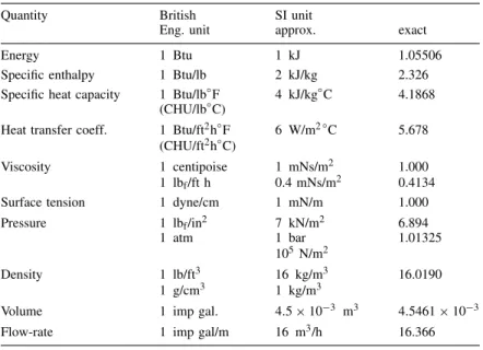
Some approximate conversion factors to SI units are given in Table 1.1. These are worth committing to memory, to give some feel for the units for those more familiar with the traditional engineering units. The exact conversion factors are also shown in the table. A more comprehensive table of conversion factors is given in Appendix D.
Table 1.1. Approximate conversion units
Quantity British SI unit
Eng. unit approx. exact
Energy 1 Btu 1 kJ 1.05506
Specific enthalpy 1 Btu/lb 2 kJ/kg 2.326 Specific heat capacity 1 Btu/lb°F 4 kJ/kg°C 4.1868
(CHU/lb°C)
Heat transfer coeff. 1 Btu/ft2h°F 6 W/m2°C 5.678 (CHU/ft2h°C)
Viscosity 1 centipoise 1 mNs/m2 1.000
1 lbf/ft h 0.4 mNs/m2 0.4134
Surface tension 1 dyne/cm 1 mN/m 1.000
Pressure 1 lbf/in2 7 kN/m2 6.894
1 atm 1 bar 1.01325
105N/m2
Density 1 lb/ft3 16 kg/m3 16.0190
1 g/cm3 1 kg/m3
Volume 1 imp gal. 4.5ð103 m3 4.5461ð103
Flow-rate 1 imp gal/m 16 m3/h 16.366
Note:
1 US gallonD0.84 imperial gallons (UK)
1 barrel (oil)D50 US gall³0.19 m3(exact 0.1893) 1 kWhD3.6 MJ
American catalogue in US gallons or gpm (gallons per minute) will have only 80 per cent of the rated capacity when measured in imperial gallons.
The electrical supply frequency in these two countries is also different: 60 Hz in the US and 50 Hz in the UK. So a pump specified as 50 gpm (US gallons), running at 1750 rpm (revolutions per second) in the US would only deliver 35 imp gpm if operated in the UK; where the motor speed would be reduced to 1460 rpm: so beware.
1.9. DEGREES OF FREEDOM AND DESIGN VARIABLES.
THE MATHEMATICAL REPRESENTATION OF
THE DESIGN PROBLEM
In Section 1.2 it was shown that the designer in seeking a solution to a design problem works within the constraints inherent in the particular problem.
In this section the structure of design problems is examined by representing the general design problem in a mathematical form.
1.9.1. Information flow and design variables
Input
Figure 1.6. The “design unit”
representing the unit are shown diagrammatically in Figure 1.6. In the “design unit” the flow of material is replaced by a flow of information into the unit and a flow of derived information from the unit.
The information flows are the values of the variables which are involved in the design; such as, stream compositions, temperatures, pressure, stream flow-rates, and stream enthalpies. Composition, temperature and pressure are intensive variables: independent of the quantity of material (flow-rate). The constraints on the design will place restrictions on the possible values that these variables can take. The values of some of the variables will be fixed directly by process specifications. The values of other variables will be determined by “design relationships” arising from constraints. Some of the design relationships will be in the form of explicit mathematical equations (design equations); such as those arising from material and energy balances, thermodynamic relationships, and equipment performance parameters. Other relationships will be less precise; such as those arising from the use of standards and preferred sizes, and safety considerations.
The difference between the number of variables involved in a design and the number of design relationships has been called the number of “degrees of freedom”; similar to the use of the term in the phase rule. The number of variables in the system is analogous to the number of variables in a set of simultaneous equations, and the number of relationships analogous to the number of equations. The difference between the number of variables and equations is called the variance of the set of equations.
If Nv is the number of possible variables in a design problem and Nr the number of design relationships, then the “degrees of freedom” Nd is given by:
NdDNvNr ⊲1.1⊳
Nd represents the freedom that the designer has to manipulate the variables to find the
best design.
IfNv DNr, NdD0 and there is only one, unique, solution to the problem. The problem is not a true design problem, no optimisation is possible.
IfNv< Nr, Nd <0, and the problem is over defined; only a trivial solution is possible. If Nv> Nr, Nd >0, and there is an infinite number of possible solutions. However, for a practical problem there will be only a limited number of feasible solutions. The
value of Nd is the number of variables which the designer must assign values to solve
the problem.
Process stream
Consider a single-phase stream, containingC components.
Variable Number
Stream flow-rate 1
Composition (component concentrations) C
Temperature 1
Pressure 1
Stream enthalpy 1
Total,Nv DCC4
Relationships between variables Number
Composition⊲1⊳ 1
Enthalpy⊲2⊳ 1
Total, Nr D2
Degrees of freedomNdDNvNr D⊲CC4⊳2DCC2
(1) The sum of the mass or mol, fractions, must equal one.
(2) The enthalpy is a function of stream composition, temperature and pressure.
Specifying (CC2) variables completely defines the stream.
Flash distillation
The idea of degrees of freedom in the design process can be further illustrated by consid-ering a simple process unit, a flash distillation. (For a description of flash distillation see Volume 2, Chapter 11).
F2, P2, T2, (xi)2
F3, P3, T3, (xi)3
F1, P1, T1, (xi)1
q
Figure 1.7. Flash distillation
The unit is shown in Figure 1.7, where:
FDstream flow rate, PDpressure,
TDtemperature,
xi Dconcentration, component i, qDheat input.
Variable Number
Streams (free variables)⊲1⊳ 3⊲CC2⊳1
Still
pressure 1
temperature 1
heat input 1
Nr D3CC9
Relationship Number
Material balances (each component) C
Heat balance, overall 1
v l e relationships⊲2⊳ C
Equilibrium still restriction⊲3⊳ 4
2CC5
Degrees of freedom Nd D⊲3CC9⊳⊲2CC5⊳DCC4
(1) The degrees of freedom for each stream. The total variables in each stream could have been used, and the stream relationships included in the count of relationships.
This shows how the degrees of freedom for a complex unit can be built up from the degrees of freedom of its components. For more complex examples see Kwauk (1956).
(2) Given the temperature and pressure, the concentration of any component in the vapour phase can be obtained from the concentration in the liquid phase, from the vapour liquid equilibrium data for the system.
(3) The concept (definition) of an equilibrium separation implies that the outlet streams and the still are at the same temperature and pressure. This gives four equations:
P2DP3DP
T2DT3DT
Though the total degrees of freedom is seen to be (CC4) some of the variables will
normally be fixed by general process considerations, and will not be free for the designer to select as “design variables”. The flash distillation unit will normally be one unit in a process system and the feed composition and feed conditions will be fixed by the upstream processes; the feed will arise as an outlet stream from some other unit. Defining the feed fixes (CC2) variables, so the designer is left with:
⊲CC4⊳⊲CC2⊳D2
as design variables.
Summary
need to calculate the degrees of freedom in a formal way. He will usually have intuitive feel for the problem, and can change the calculation procedure, and select the design variables, as he works through the design. He will know by experience if the problem is correctly specified. A computer, however, has no intuition, and for computer-aided design calculations it is essential to ensure that the necessary number of variables is specified to define the problem correctly. For complex processes the number of variables and relating equations will be very large, and the calculation of the degrees of freedom very involved. Kwauk (1956) has shown how the degrees of freedom can be calculated for separation processes by building up the complex unit from simpler units. Smith (1963) uses Kwauk’s method, and illustrates how the idea of “degrees of freedom” can be used in the design of separation processes.
1.9.2. Selection of design variables
In setting out to solve a design problem the designer has to decide which variables are to be chosen as “design variables”; the ones he will manipulate to produce the best design. The choice of design variables is important; careful selection can simplify the design calculations. This can be illustrated by considering the choice of design variables for a simple binary flash distillation.
For a flash distillation the total degrees of freedom was shown to be (CC4), so for
two componentsNdD6. If the feed stream flow, composition, temperature and pressure
are fixed by upstream conditions, then the number of design variables will be:
N0
dD6⊲CC2⊳D64D2
So the designer is free to select two variables from the remaining variables in order to proceed with the calculation of the outlet stream compositions and flows.
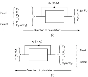
If he selects the still pressure (which for a binary system will determine the vapour liquid equilibrium relationship) and one outlet stream flow-rate, then the outlet compo-sitions can be calculated by simultaneous solution of the mass balance and equilibrium relationships (equations). A graphical method for the simultaneous solution is given in Volume 2, Chapter 11.
However, if he selects an outlet stream composition (say the liquid stream) instead of a flow-rate, then the simultaneous solution of the mass balance and v l e relationships would not be necessary. The stream compositions could be calculated by the following step-by-step (sequential) procedure:
1. Specifying P determines the v l e relationship (equilibrium) curve from
experi-mental data.
2. Knowing the outlet liquid composition, the outlet vapour composition can be calcu-lated from the v l e relationship.
3. Knowing the feed and outlet compositions, and the feed flow-rate, the outlet stream flows can be calculated from a material balance.
4. An enthalpy balance then gives the heat input required.
x3
Figure 1.8. Information flow, binary flash distillation calculation (a) Information recycle (b) Information flow reversal
effect reverses the flow of information through the problem and removes the recycle; this is shown diagrammatically in Figure 1.8.
1.9.3. Information flow and the structure of design problems
It was shown in Section 1.9.2. by studying a relatively simple problem, that the way in which the designer selects his design variables can determine whether the design calculations will prove to be easy or difficult. Selection of one particular set of variables can lead to a straightforward, step-by-step, procedure, whereas selection of another set can force the need for simultaneous solution of some of the relationships; which often requires an iterative procedure (cut-and-try method). How the choice of design variables, inputs to the calculation procedure, affects the ease of solution for the general design problem can be illustrated by studying the flow of information, using simple information flow diagrams. The method used will be that given by Leeet al. (1966) who used a form of directed graph; a biparte graph, see Berge (1962).
The general design problem can be represented in mathematical symbolism as a series of equations:
fi⊲vj⊳D0 where jD1,2,3, . . . , Nv,
iD1,2,3, . . . , Nr
Consider the following set of such equations:
f3⊲v1,v3,v4⊳D0
f4⊲v2,v4,v5,v6⊳D0
f5⊲v5,v6,v7⊳D0
There are seven variables, NvD7, and five equations (relationships) NrD5, so the
number of degrees of freedom is:
NdDNvNr D75D2
The task is to select two variables from the total of seven in such a way as to give the simplest, most efficient, method of solution to the seven equations. There are twenty-one ways of selecting two items from seven.
In Lee’s method the equations and variables are represented by nodes on the biparte graph (circles), connected by edges (lines), as shown in Figure 1.9.
f1
v1 v1
f node
v node
Figure 1.9. Nodes and edges on a biparte graph
Figure 1.9 shows that equation f1 contains (is connected to) variablesv1 and v2. The
complete graph for the set of equations is shown in Figure 1.10.
f1 f2 f3 f4
v1 v2 v3 v4 v5 v6 v7
f5
Figure 1.10. Biparte graph for the complete set of equations
The number of edges connected to a node defines the local degree of the node p.
For example, the local degree of the f1 node is 2,p⊲f1⊳D2, and at thev5 node it is 3, p⊲v5⊳D3. Assigning directions to the edges of Figure 1.10 (by putting arrows on the
lines) identifies one possible order of solution for the equations. If a variablevjis defined
as an output variable from an equation fi, then the direction of information flow is from
the node fi to the nodevj and all other edges will be oriented into fi. What this means,
mathematically, is that assigningvj as an output from fi rearranges that equation so that:
fi⊲v1,v2, . . . ,vn⊳Dvj
The variables selected as design variables (fixed by the designer) cannot therefore be assigned as output variables from an f node. They are inputs to the system and their edges must be oriented into the system of equations.
If, for instance, variablesv3 and v4 are selected as design variables, then Figure 1.11
shows one possible order of solution of the set of equations. Different types of arrows are used to distinguish between input and output variables, and the variables selected as design variables are enclosed in a double circle.
f1 f2 f3 f4 f5
v1 v2 v5 v6 v7
v3 v4
Design variables (inputs) Inputs
Outputs
Figure 1.11. An order of solution
Tracing the order of the solution of the equations as shown in Figure 1.11 shows how the information flows through the system of equations:
1. Fixingv3 and v4 enables f3 to be solved, giving v1 as the output.v1 is an input to
f1 and f2.
2. Withv1 as an input, f1 can be solved givingv2;v2 is an input to f2 and f4.
3. Knowingv3,v1 andv2, f2 can be solved to givev5;v5 is an input to f4 and f5.
4. Knowingv4,v2 andv5, f4 can be solved to givev6;v6 is an input to f5.
5. Knowingv6 andv5, f5 can be solved to give v7; which completes the solution.
This order of calculation can be shown more clearly by redrawing Figure 1.11 as shown in Figure 1.12.
f3 v1 f1 v2 f2 v5 f4 v6 f5 v7 v3
v4
v2
v5
v3
v4