i
Proceeding
SCESCM 2012
Sustainable Civil Engineering Structures and
Construction Materials
Yogyakarta, September 11 – 13, 2012
Editors :
Priyosulistyo, Suhendro B., Kanie S., Satyarno I., Senjutichai T., Triwiyono A., Sulistyo D., Siswosukarto S., Awaludin A.
Departement of Civil and Environmental Engineering
Faculty of Engineering
ii The 1st International Conference on Sustainable Civil Engineering Structures and Construction Materials Yogyakarta, Indonesia 2012
ORGANIZING ASSOCIATION :
EDITORS :
Priyosulistyo Bambang Suhendro Shunji Kanie Iman Satyarno
Teerapong Senjutichai Andreas Triwiyono Djoko Sulistyo
Suprapto Siswosukarto Ali Awaludin
Published by :
Department of Civil and Environmental Engineering Universitas Gadjah Mada, Yogyakarta, INDONESIA Website : http://tsipil.ugm.ac.id
Tel : +62-274-545675 Fax : +62-274-545676
ISBN : 978-602-95687-7-6
Copyright ©2012 by Department of Civil and Environmental Engineering, UGM
The texts of the papers in this volume were set individually by the authors or under their supervision.
ṻ
6. Experimental Study on Comfinement Effect of Hoop Reinforcing Bar for New Shear Connector Using Steel Pipe
Y. Matsuo, T. Ueda, H. Furuuchi, R. Yamaguchi, K. Nakayama ... 112 7. Puching Shear Behavior of Overlay Strengthened RC Slab Under Traveling Wheel-Type
Fatigue Loading
Y. Shimanaka, T. Ueda, H. Furuuchi, D. Zhang, T. Tamura, S-C. Lim ... 117 8. Lateral Load-Slip Curve of Steel-wood-steel Bolted Timber Jpints Composed of Several
Layers with Different Specific Gravities
E. Pesudo, A. Awaludin, B. Suhendro ... 124 9. Finite Element Modeling of the Transition Zone Between Aggregate and Mortar in
Concrete
Han Ay Lie, Parang Sabdono, Joko Purnomo ... 130 10. Shear Strength of Normal to High Strength Concrete Walls
J. Chandra, S. Teng ... 138 11. Nonlinear Analysis of Reinforced Concrete Beams Using FEM with Smeared Crack
Approach, Mohr’s Failure Criteria, and The Tomaszewicz Model
Sri Tudjono, Ilham Maulana, Lie Hendri Hariwijaya ... 146 12. Flutter Analysis of Cable Stayed Bridge
Sukamta ... 154 13. Lesson Learned From The Damage Of Academic Buildings Due To Earthquake in
Padang, Sumatera
Djoko Sulistyto, Suprapto Siswosukarto, Priyosulistyo, Andreas Triwiyono, Ashar
Saputra, Fauzie Siswanto ... 157 14. The Flexural Behavior in Perpendicular Direction of Concrete Brick Walls with
Wiremesh Reinforcement and Their Application for Simple Houses
N. Wardah, A. Triwiyono, Muslikh ... 166 Material Engineering
1. Mechanical Properties of Gunny Sack Fiber Concrete
Antonius, Himawan Indarto, Devita Kurniastuti ... 172 2. Development and Optimization of Cement Based Grouting Materials
R. Breiner, E. Bohner, H. S. Mṻller ... 177 3. A Review on Test Results of Mechanical Properties of Bamboo
I.G.L.B. Eratodi, A. Triwiyono, A. Awaludin, T.A. Prayitno ... 186 4. Application of Wood Stave Pipeline in Seropan Caves
A. Hayuniati, A. Awaludin, B. Suhendro ... 193 5. The Characteristic of Ultrasonic Pulse Velocity (UPV) On Mortar With Polypropylene
Fibers As Additives
Faqih Ma’arif, Priyosulistyo, Hrc ... 199 6. Precast Concrete Construction : A Green Construction Case Study : Comparison of
Construction Energy and Environmental Influence in Low Cost Housing Construction in Batam
Hari Nugraha Nurjaman, Haerul Sitepu, H.R. Sidjabat ... 207 7. Evaluation of ISO 22157-2 Test Method for Tension Parallel to Grain of Petung Bamboo
(Dendrocalamus asper)
I.S. Irawati, B. Suhendro, A. Saputra, T.A. Prayitno ... 216 8. Compression Fracture Energy of Cement Treated Sands
K. A. Tariq, T. Maki ... 223 9. Effects of Steel and Polypropylene Fiber Addition on Interface Bond Strength Between
Normal Concrete Substrate and Self-Compacting Concrete Topping
Slamet Widodo, Iman Satyarno, Sri Tudjono ... 228 10. Influence Of Portland Cement Paste Quantity and Quality on Early Age Compressive
Strength of Mortar
temb
The 1st International Conference on Sustainable Civil Engineering Structures and Construction Materials
Finite Element Modeling of the Transition Zone between Aggregate and
Mortar in Concrete
Han Ay Lie
Department of Civil Engineering, Diponegoro, Semarang, Indonesia
Parang Sabdono, Joko Purnomo
Construction and Material Laboratory, Department of Civil Engineering, Diponegoro, Semarang, Indonesia
Abstract:
Visual observations to the Interfacial Transition Zone (ITZ) between aggregate and mortar in concrete showed that this area differs significantly to the bulk mortar, further away from the ITZ. This ITZ has a higher porosity with a dissimilar crystal formation, therefore becoming the weak linkin the material. In the past, concrete was seen as a two-phase material consisting of mortar and aggregates only. However, analyzing the material as a three-phase composite including the ITZ, will give a more realistic representation to its behavior. A Finite Element Model (FEM) was developed. The ITZ is modeled as a linkage element having a double spring, perpendicular and parallel to the ITZ surface. The individual load-deformation responses of these springs were obtained from laboratory tested specimens. Non-linearity is generated by evaluating the principal stresses at Gauss points, using the Kupfer-Hilsdorf-Rusch (1969) failure envelope and the CEB-FIB 2010 code. Iteration is conducted by the arc-length method developed by Riks-Wempners. The load-displacement curves resulted by the FEM were validated to laboratory tested specimens curves, to compare its effectiveness and asses the sensitivity of the model.Keywords
: ITZ, Linkage-element, non-linearity, failure criteria.1 INTRODUCTION
1.1 The Interfacial Transition Zone (ITZ)
The presence of the aggregate-to-mortar ITZ is to date, widely acknowledged and recognized as the
“weak link”in concrete. This weakness is due to the low adhesive strength, highly depending on the volume and size of voids in the ITZ. Also, the characteristics of large crystals tend to posses less adhesion capacity. These calcium hydroxide crystals have an orientation that allows cracks to occur along their weak bond plane. Further, micro cracks tend to propagate along the weak plane of the crystals following the plane of Van der Waalsforces.
Due to its very small size, only 30 to 50 μm in
thickness, direct tests methods to obtain the ITZ properties are up till now, at not available. The most recent technique is the micro-indentation method, measuring the modulus of elasticity and creep from the indentation at a distance from the ITZ.
When constructing a model, the majority of Finite Element Models (FEM) represents the bond in the ITZ by the smeared-crack method, allowing crack propagation along its surface. The constitutive model for the bond relationship is highly simplified. The most widely chosen approach is the inverse modeling technique. For this technique, a simplified laboratory specimen is constructed to function as calibrating tool to numerical or FE models, assuming the mortar matrix as a continuum element. The ITZ itself is
assumed homogeneous; variation along the aggregate surface is usually not incorporated into the model. 1.2 Modeling the ITZ
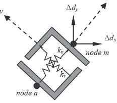
In this research work, the ITZ is modeled as a linkage element consisting of two springs, one perpendicular and one parallel to the ITZ surface, characterizing its normal and shear behaviors (Figure 1). The linkage element is connected by two nodes, one on the aggregate surface, denoted as "a" and one at the mortar element denoted by "m". The nodes have two degrees of freedom each.
Figure 1: Linkage element model for the ITZ
The stiffness modulus' of the springs kn and kv are expressed in their load-displacement responses and obtained by specific developed, individual laboratory tests (Han and Nuroji, 2010; Han and Sabdono, 2011). When stresses increase, the relative displacements in the global coordinate system are converted to the coordinate system of the linkage element, to update the corresponding stiffness modulus. Due to the highly non-linear nature of the
n
v
kn
kv
node a
node m Δdx Δdy
temb The 1st International Conference on Sustainable Civil Engineering Structures and Construction Materials
Due to its very small size, only 30 to 50 μm in Δ
Δ
130
cementitious material and the ITZ, the arc-length iteration technique is accessed, to accommodate this behavior in the structure.
1.3 ITZ Load - Displacement Responses
The ITZ load-displacement responses are defined by a series of factors such as the roughness of the aggregate surface, the mechanical properties of the mortar, the water cement ratio and the presence of bleeding. The normal response is obtained by recording the behavior of a cylindrical aggregate, attached to a mortar surface. A tensile load is generated by the Dyna Proceq halftprufer Z16, and the displacement recorded by three crack clips connected to a data logger (Figure 2).
Figure 2: Testing the normal response of the ITZ
The shear response is measured by applying a uniform compression load to a square aggregate, embedded in a mortar block. The bond of two opposite sides of this aggregate to the mortar is prevented by inserting a 150μm Teflon sheet. Mortar confinement is monitored by two strain gauges attached perpendicular to the ITZ surface (Figure 3).
Figure 3: Testing the shear response of the ITZ
The resulting load-displacement response in the normal direction is characterized by a polynomial to the second degree. The curve shows a distinctively non-linear behavior, even at very low loading levels. The ultimate capacity occurs due to bond failure in the ITZ. The load-displacement relationship for the ITZ in shear has a bi-linear function, the first part representing the stiffness modulus as a contribution of adhesion and friction, and the second being purely the result of friction and fine aggregate interlocking.
The resulting load-displacement responses in the normal and shear directions, and their comparisons are shown in Figure 4. It can be seen that the ultimate normal displacement is relatively low, when compared to shear. It is therefore most likely that failure in the ITZ will be initiated in the tension area.
Figure 4: ITZ stiffness behavior
2 ITZ MODELING
2.1 The linkage element's stiffness matrix.
The two springs are characterized by their relative movements; one in the direction perpendicular to the ITZ surface and in this research work denoted as the
normalresponse, and one parallel to the ITZ surface, defined as to be the shearresponse. Since the relative displacement of the two adjacent nodes represents the behavior of the spring, these displacements should be transformed from the global coordinate system (X, Y)
to the local coordinate system (n, v). The local coordinate system is demarcated at the bisection line of the angle between the two ITZ surfaces of the aggregate (Figure 5).
Figure 5: Linkage degrees of freedom
temb
The 1st International Conference on Sustainable Civil Engineering Structures and Construction Materials
⎣
Introducing the transformation matrix [R]
[�] =�
The linkage stiffness matrix [k] is written as:
[�] =�
[ΔP]and [Δd]are respectively the increment force and the increment node displacement matrix of the link in the global coordinate system, and α is the angel between the local and global coordinate system following the right-hand rule.
The matrix can now be assambaged into the structural stiffness matrix, and used to perform the finite elenement analysis. At primary stage, the coordinates of the linkage element nodes at the aggregate and mortar, are identical. When an increment load is applied to the system, the relative displacement between the two nodes is calculted. ∆�� is the relative movement of the normal spring (Figure 6). The direction of the Δ������⃑� vector is used as criterion in the analysis of the ITZ.
Figure 6: Linkage element algorithms
When this vector moves in the positive direction, the normal spring is in tension and the stiffness of this spring will decrease as a function of the load increase. But when the vector moves in the negative direction, the spring is in compression, resulting in a fully bonded condition. The corresponding stiffness will therefore be infinitely large approaching ∞, and it is assumed that the two nodes a and m will coincide, thus further having identical displacements throughout the loading process. While a monotonic loading does not influence the behavior analysis, since shear is not direction sensitive. The algorithm for the linkage However, since the shear capacity is much higher than the normal capacity, the kv will still remain in the equation and ITZ failure is due to tension. Secondly is the case were the total shear-displacement dv surpasses the ultimate shear displacement (dv)ult. In this case the ITZ will fail in shear. When the stiffness matrix of the linkage element reaches zero, the bond within the ITZ has vanished and this will result in a physical gap in the ITZ. During testing procedure of the laboratory specimens, the propagation of this gap can clearly be observed (Figure 7).
Figure 7: ITZ failure in tension
temb The 1st International Conference on Sustainable Civil Engineering Structures and Construction Materials
⎣
eventually very small, the stiffness's of the springs are around 60 MPa.
2.2 Spring movement algorithms.
The direction of the positive normal coordinate in the local system is determined by the vector approach. The vectors between the two adjacent notes are converted to a unity vector [R][i,j], and their resultant calculated. The coefficient of this resultant vector is converted to the opposite direction by applying a negative sign to the [i,j] matrix (Figure 8).
Figure 8: Algorithms for the ITZ in tension
[��] =����−1− �� and �is the length between two adjacent nodes.���� is the unity vector
3 FINITE ELEMENT ANALYSIS
3.1 Failure criteria.
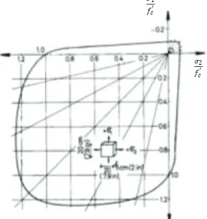
The overall model consists of the ITZ, the bulk matrix and the aggregate, modeled as a four point isoparametric quadrilateral. The matrix is evaluated based on the principal stresses at the Gauss points. Failure criterion is distinguished either as crushing or fracture of the mortar matrix. Based on the Kupfer-Hilsdorf-Rusch’s (1969) failure envelope (Figure 9) crushing will occur in the third quadrant, when all principal stresses are in compression. The first quadrant is fracture due to tension, while the remaining quadrants characterize the
tension-compression failure. In this area the principal tensile stresses will initiate cracking of the material, and further the material in compression will undergo a strain increase. This approach is adopted by the CEB-FIB 2010 code.
Figure 9. Kupfer-Hilsdorf-Rusch Failure Envelope
Fracture of a Gauss point under a certain loading increment, will influence the stiffness of its element, and a reduction in the element stiffness matrix will be resulted. Progressive loading will lead to failure of one or more Gauss points up till collapse of the element as a whole(Han and Purnomo, 2011).
3.2 Material nonlinearity, isotropic and orthotropic behavior.
3.2.1 Compression behavior
Various numerical expressions are available, covering both the ascending and descending branches of the uni-axial stress-strain relationship of concrete in compression. In this work the CEB-FIB (2010) model was chosen, giving the expression:
�
The failure criterion is expressed either in terms of the three stress invariants �(�1,�2,�3) = 0in the Haigh - Westergaard system, or in the hydrostatic system as
�(�,�,�) = 0. Tensile stresses are signed positive and compression negative. Expressed in terms of their invariants, the function becomes �(�1,�2,���3�) = 0
temb
The 1st International Conference on Sustainable Civil Engineering Structures and Construction Materials
compression f2f. At failure the value of β = 1 (Figure
most compressive principal stress, the overall behavior is covered solemnly withinthe boundaries of the failure envelope. The material is therefore assumed to behave isotropic, and the constitutive formulation for the material is based on the equation (10). The material stiffness modulus is represented by the major principal stress. Figure 11 represents the visualization of a failed element under biaxial compression (Chen, 2007).
Figure 11. Failure due to crushing of concrete
[�] = �
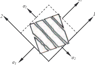
within the failure envelope, the element is un-cracked and the material behavior is considered isotropic. Since both stresses and strains are relatively very low, the stiffness modulus is taken as the initial tangent stiffness E0. Tensile failure produces a totally different failure pattern as compared to the compression failure configuration. When the stresses at Gauss points enter the boundary of the envelope, micro cracks will propagate in the direction of the most principal tensile stress (Figure 12). Past cracking, the material is no longer considered
isotropic. Evaluate the element as an orthotropic material, enables the behavior in both principal directions to be adjusted to actual stress levels. In this work the model of Chen and Saleeb (1982); Chen, (2007)is used to represent the material behavior after
cracking. The formulation is derived based on the assumption that cracks are formed only in the plane perpendicular to the xy plane and that the sliced material between two adjacent cracked planes is linearly elastic and transversely isotropic in the principal axes coordinate system.
Figure 12. Cracking of concrete in tension
This model is formulated assuming that the principal axes of material orthotropy coincide with the principal stress directions, and then transformed into the non-orthotropic set of axes (x, y).
[�] = 1 axes and obtained from the corresponding stress-strain relationship (Kwak and Filippou, 1992). The E1 is oriented perpendicular to the crack direction. The lower-right-hand term of the matrix represents the shear behavior which is, in lieu of the lack in experimental evident, obtained such that the 1/G factor remains invariant with respect to the rotation of coordinate axes. The Poisson ratio is considered a constant, equal to the initial tangent value in uni-axial compression.
3.2.3 Tension-compression behavior
The compression-tension bi-axial condition is the most sensitive in analysis. Due to the shape of the failure envelope, failure due to cracking of concrete in the principal tensile direction becomes the most prominent failure mode. Within the limits of the envelope, the assumption that the material behavior is isotropic can still be sustained, especially since stress and strain levels are very low. The isotropic constitutive material model with the initial tangent
temb The 1st International Conference on Sustainable Civil Engineering Structures and Construction Materials
β representation to the actual behavior.
When cracks start to propagate, as soon as the biaxial stress combination exceeds the failure envelope boundaries, the orthotropic model is accessed. Based on research work done by Vecchio and Collins (1986)
the rotation angel 2θ for stresses, closely approaches the rotation angle for strain. Hence, the principal strainscan be obtained based on the rotation angel of stresses and their corresponding strains. The stress-strain relationship for the tensile behavior in biaxial compression-tension aftercracking is as follows:
�2��� =
From the equations, the secant modulus of elasticity is calculated.
��� =��22 = ����0.8(2������+ 0.34 −�2)�1� (14)
Where σ2 is the major principal stress in compression.
f'c is the concrete compressions strength in uni-axial compression and Ecm is the modulus of elasticity at peak stress in compression. Further, ε1 and ε2 are respectively the principal tensile and compression strain at the ith iteration, and εcm is the strain at peak stress in uni-axial compression taken as 0.0022 (Figure 13).
Figure 13. Stress-strain behavior for biaxial stresses (Vecchio and Collins, 1986)
3.3 Programming language and iteration techniques.
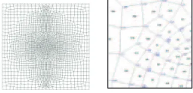
To obtain the coordinates of element nodes, a mesh generator is used. The meshing generator QUAD beta-version was developed in Australia. The program consist of two base programs the QB and QPRO40, the later is to observe the mesh structure and to evaluate the outputs. The generator is based on the
Lagrangian (Joseph Louis Lagrange, 1813) analysis and can incorporate double nodes, as well as bandwidth mapping.
The structure is isolated by defining its corner coordinates; lines or arches are drawn to connect these lines. For an arch, the centre point should also be designated. At the second step, the areas, and the fines degree of meshing are set on the borders of the area and the program will generate a smooth four-node element mesh with no ill elements. The program enables node and element labeling. This option is very useful when examining the stress behavior of the element, and the displacement state of the ITZ.
To create double nodes along the ITZ, two arches coinciding each other, are created. The two arches need to have concurring starting and ending nodes but individually assigned, different numeration. When the arches are meshed with an equal number of elements, but the area between the two arches is not defined into elements, a blank or gap in between these two arches will be created. The output of the generator is called by the Visual Basic (Microsoft Visual Studio 2008)
program to support the Finite Element analysis. Based on preliminary studies and observing the crack pattern of the validation specimens, finer meshing can be placed in the areas that are most vulnerable to high principal stresses and failure.
Figure 14. Meshing and labeling of a one inclusion model
To accommodate the nonlinearity of the model, the arch-length iteration technique is applied. This iteration method is based on the assumption that within a given load increment, the path follows a constant arc, defined by the structural stiffness at a convergence state (Wempner, 1971; Riks, 1972,).The
temb
The 1st International Conference on Sustainable Civil Engineering Structures and Construction Materials
0
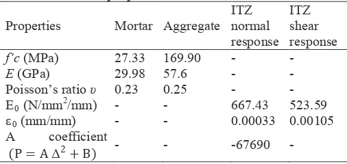
4.1 Validation to experimental tests specimen
The model is run for a mortar cube 100 x 100 x 50 mm, having single cylindrical aggregate inclusions, 45 mm in diameter. The mechanical properties of the mortar, aggregate and the ITZ are obtained from laboratory tested specimens and listed in Table 1. The laboratory specimens were tested with a constant incremental load, resulting in a constant displacement. Table 1: Material properties
To evaluate the ITZ algorithms, the correctness of the spring in the normal direction is tested for an arbitrarily load. Figure 15 shows the response of the spring in the model. The gray dots represent the normal linkage element in tension, while the black dots represent compression. The outcome of the FEM program is confirmed by the visual observation of the laboratory tested specimen.
Figure 15. Diagnostic of the ITZ responses
Additionally, the FEM program was run to compare the influence of the ITZ on the overall structural behavior. Figure 15 shows the load-displacement responses for the structure neglecting the ITZ, and including the linkage element, representing the ITZ. It is shown that a lower stiffness modulus is obtained when the behavior of the ITZ is included.
The FEM assuming a fully bonded condition, without the presence of the ITZ results in a higher stiffness modulus at every loading stage, when compared to the model incorporating the ITZ for the same loading
levels. The model also over predicts the actual load-displacement behavior of the laboratory tested specimen, significantly. While the ultimate capacity was estimated closely by both the models, the FEM with the ITZ demonstrated a slightly lower stiffness when compared to the laboratory specimen.
Figure 16. Load-displacement relationship comparison
As for the ductility, it can be seen that neglecting the ITZ will predict a much lower ultimate value, resulting in a less ductile structure. However, the load-displacement curves of the FEM and laboratory specimen are identical, following a non-linear response, even at low loading stages. The parabolic curve reaches a maximum, and demonstrates a very slight descending branch, up till failure.
4.2 Conclusion and future research work
The presence of the ITZ in the analysis of composite structures and materials could not be neglected. The developed FEM program modeling the ITZ as a linkage element is therefore most useful to obtain a more realistic and accurate prediction of the load-displacement response. This program also includes the non-linear nature of the cementitious material.
The modeling of the ITZ as a double spring is appropriate in representing the behavior of the interface. This model can be basically expanded for incorporation of the ITZ behavior for various materials, since the normal and shear behavior are obtained through individual tests. However, further research need to be conducted, to investigate as whether indeed, the load-displacement relationships of normal and shear stiffness is independent. The assumption that when the normal spring in compression, a totally bounded condition exist, is also not completely true.
temb The 1st International Conference on Sustainable Civil Engineering Structures and Construction Materials
Δ
ata
TZ
3 8 υ
)
ε 3 5
ent
Δ B)
100
136
should be studied. From here on, the stiffness matrix of the ITZ could be constructed, reflecting the interaction between shear and normal behavior. In the special case of bar reinforcement, the shear behavior can be approached by the constitutive model representing the bond between the bar and the concrete.
The FEM program is operated using the full, square matrix based on the Gauss elimination method. When dealing with more complicated configurations, for example deformed steel bars that requires very fine, complex meshing, the band-width method should be accessed enabling a shorter running time.
A sensitivity analysis including the effect of loading increments and meshing should be conducted, to test the accuracy and effectiveness of the developed program. More elaborate laboratory test specimens will be used to validate the outcome, for various types of mortar mixes, and diversity in steel properties. The outcome of these validations and sensitivity analysis will be used to improve and correct the ITZ program.
REFERENCES
Chen, W. F. and Saleeb, A. F., 1982, “Constitutive Equations for Engineering Material, Vol. 1: Elasticity and Modeling”, John Wiley and Sons, IBN 0-471-09149-9.
Chen, W. F., 2007, “Plasticity in Reinforced Concrete”, Ross J. Publishing, ISBN-13: 978-1-932159-74-5.
FIB Bulletin Nr. 55 and 56, 2010, “Model Code 2010”, First Complete Draft, Vol. 1 and 2, ISBN 978-2-88394-095-3/6, Federal Institute of Technology, Lausanne, Switzerland.
Han, A. L. and Nuroji, 2010, “The Normal and Shear Modulus Properties of the Interfacial Transition Zone in Concrete; Newly Developed Testing Procedures”,
Proceeding of the 35thCoral Anniversary Conference on Our World in Concrete and Structures, Singapore. Han, A. L. and Purnomo, J., 2011, “Finite Element Modeling Incorporating Non-Linearity of Material behavior Based on the FIB Model Code 2010”,
Journal of Applied Technology and Innovations, ISSN
1804-4999, Vol. 5. pp.
52-62. http://academicpublishingplatforms.com.
Han, A. L. and Sabdono, P., 2011, “Experimental Study to the Load-Displacement Response of the Interfacial Transition Zone in Concrete”, The 3rd International Conference European Asian Civil
Engineering Forum (EACEF), Designing and Constructing Sustainability, Yogyakarta, Indonesia.
Kupfer, H., Hilsdorf, H. K. and Rusch, H., 1969, “Behavior of Concrete Under Biaxial Stresses”,
American Concrete Institute Journal, Proceedings
Vol. 66, no. 8, August 1969, pp. 656-666.
Kwak, H.G. and Filippou, F. C., 1992, "Finite Element Analysis of Reinforced Concrete Structures Under Monotonic and Cyclic Loads",10th World Conference in Earthquake Engineering, Madrid, Spain.
Ottosen, N. S., 1979, “Constitutive Model for Short-Time Loading of Concrete”, Journal of the Engineering Mechanics Division, ASCE, Vol. 105, no. EM1, pp. 127-141.
Riks, E., 1970, “An Incremental Approach to the Solution of Snapping and Buckling Problems”,
International Journal of Solids and Structures, Vol. 15, no. 7, pp. 529-551.
Task Group 8.2, CEB-FIB, 2008, State-of-art report on “Constitutive Modelling of High Strength/high Performance Concrete”, International Federation for Structural Concrete, Switzerland.
Vecchio, F. J. and Collins, M. P., 1986, “The Modified Compression-Field Theory for Reinforced Concrete Elements Subjected to Shear”, ACI Journal Proceedings, Vol. 83, no.2, pp. 219-231.
Wempner, G. A., 1971, “Discrete Approximations Related to Nonlinear Theories of Solids”,
International Journal of Solids and Structures, Vol. 7, no. 11, pp. 1581-1599.