FAKULTI KEJURUTERAAN ELEKTRIK
UNIVERSITI TEKNIKAL MALAYSIA
MELAKA
LAPORAN PROJEK
SARJANA MUDA
MODELLING OF A SMALL SCALE QUADROTOR SYSTEM
Lim Kian Wee
“I hereby declare that I have read through this report entitle “Modelling of a Small Scale Quadrotor System” and found that it has comply the partial fulfillment for awarding the degree of Bachelor of Mechatronics Engineering”
MODELLING OF A SMALL SCALE QUADROTOR SYSTEM
LIM KIAN WEE
A report submitted in partial fulfillment of the requirements for the degree of Mechatronics Engineering
Faculty of Electrical Engineering UNIVERSITI TEKNIKAL MALAYSIA
MELAKA
I declare that this report entitle “Modelling of A Small Scale Quadrotor System” is the result of my own research except as cited in the references. The report has not been accepted for any degree and is not concurrently submitted in candidature of any other degree.
Signature : ...
Name : ...
ACKNOWLEDGEMENT
Firstly, I am grateful that I have Madam Norafizah Binti Abas as my supervisor for my final year project who has been guiding me throughout the period of the final year project. I would like to thank her for her patience and motivation while guiding me to a better track of conducting this final year project. Her guidance on the report has helped a lot as she has the willingness to sacrifice her time on checking my report words by words. I would also very appreciate her as she always share her experience with us.
Secondly, I would like to thank Ms. Nur Maisarah Bt Mohd Sobran, who is my supervisor for my final year project. She had been guiding me a lot on the writing of the report. Furthermore, she has gave me encouragement and taught me the knowledge of writing the report of final year project.
Besides, I would like to thank my friends who are also the final year students that are under the supervision of Madam Norafizah Binti Abas. Throughout the period of this final year project, I am able to learn extra knowledge through other projects via discussion among each other. The discussion is very meaningful as the topic that is being discussed is quite challenging where every student able to exchange their opinion with each other. Thus, this has make the final year project more interesting.
ABSTRACT
ABSTRAK
TABLE OF CONTENTS LIST OF APPENDICES xi
1 INTRODUCTION
1.1 Research background
1.2 Motivation and significant of research 1.3 Problem statement
2.1 Theories and basic principles
2.1.1 Newton-Euler formulation method 2.1.2 SimMechanics Toolbox
2.1.3 SimMechanics Link
2.2 Review of Previous Related Works 2.2.1 Method of Modelling
2.2.2 Overall System
2.2.3 Experiments Conducted
2.3 Summary and Discussion of the Review
3.1 Project Overview
3.3 Derivation of Mathematical Modelling 3.3.1 Dynamic Modelling of Quadrotor
4 RESULT AND DISCUSSION
4.1 Introduction
4.2 Results of Computational Modelling 4.2.1 Assembly of Testbed
4.2.2 The Block Diagram 4.2.3 Analysis of the Testbed
4.2.4 Mathematical Model of Quadrotor 4.3 Results of Physical Realisation Experiments
4.3.2 Results of Force-lift and Rotor’s Speed 4.4 Analysis for Mathematical Model of
Quadrotor
5.2 Suggestion for Future Work
LIST OF TABLES
TABLE TITLE PAGE
2.1 The summary of each journal 19
2.2 The methods and the hardware configuration for this project 21
4.1 List of components used in Testbed 47
4.2 4.3
Force generated with given angular velocity
Results of the simulation on testing the thrust force and drag force
51 52 4.4 The physical measurement of the respective components based on
description
Results of the simulation on testing the thrust force for Motor 1 The results of the force-lift test for motor 2
Results of the simulation on testing the thrust force for Motor 2
57 58 59 4.9
4.10
The results of the force-lift test for motor 3
Results of the simulation on testing the thrust force for Motor 3
60 61 4.11 The results of the force-lift test for motor 4 62 4.12
4.13
Results of the simulation on testing the thrust force for Motor 4 Result of the Force-Lift Test
LIST OF FIGURES
FIGURE TITLE PAGE
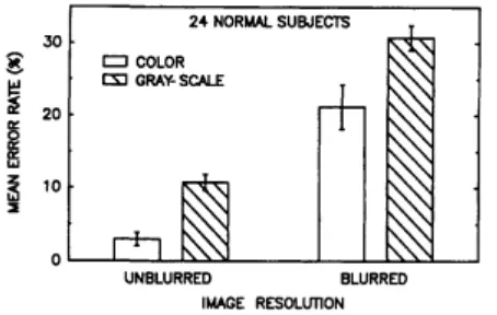
1.1 Convertawings Model A. First Quadrotor that able to fly 2 1.2 Percentage of images incorrectly identified for four stimulus
conditions with standard error bars.
3
2.1 Coordinate System of Quadrotor 12
2.2 The X-shaped Unmanned Aerial Vehicle, Quadrotor 13
2.3 The top view of a + shaped Quadrotor 14
2.4 The movements of the Quadrotor 14
2.5 The dynamics of Quadrotor 15
3.1 Overall project flowchart 24
3.2 Definition of Axes 28
3.3 An assumption of a Quadrotor shape for derivation of inertia 31 3.4 The definition of forces and torques acting on the motors of the
Quadrotor
33
3.5 The process for Computational Modelling 37 3.6 The flowchart of the process in SimMechanics Toolbox 40
4.1 The assembly of the Quadrotor 47
4.2 4.3
The block diagram after the conversion from Solidwork The mass properties of the testbed Quadrotor
48 49 4.4 Result for one of the flow simulation test 50 4.5 The graph of Force against Duty Cycle Computationally 51 4.6 The graph of Force against Duty Cycle for Motor 1 57 4.7 The graph of angular velocity against the duty cycle of motor 1 57 4.8 The graph of force against the duty cycle of motor 2 59 4.9 The graph of angular velocity against the duty cycle for motor
2
59
3
4.12 The graph of force against the duty cycle for motor 4 63 4.13 The graph of the angular velocity against the duty cycle of
motor 4
63
4.14 The graph of yaw of the Quadrotor system 65 4.15 The graph of output and input in pitch movement for
computational modelling
70
4.16 The graph of output and input in yaw movement for computational modelling
70
4.17 The graph of output and input in roll movement for computational modelling
70
4.18 The graph of output and input in z direction for computational modelling
71
4.19 The graph of output and input in y direction for computational modelling
71
4.20 The graph of output and input in x direction for computational modelling
71
4.21 The graph of output and input in pitch movement for physical modelling
73
4.22 The graph of output and input in yaw movement for physical modelling
73
4.23 The graph of output and input in roll movement for physical modelling
73
4.24 The graph of output and input in z direction for physical modelling
74
4.25 The graph of output and input in y direction for physical modelling
74
4.26 The graph of output and input in x direction for physical modelling
LIST OF APPENDICES
APPENDIX TITLE PAGE
A Gantt Chart of the Research 82
B The sketch of the testbench used in Bifilar Pendulum Experiment with the dimensions.
83
C The components of the Quadrotor with dimensions.
84
D Coding in MATLAB for modelling computationally
86
E Block diagram of the open loop system of modelling computationally
87
F Coding in MATLAB for modelling physically 88 G Block diagram of the open loop system of
modelling physically
INTRODUCTION
1.1 Research Background
In this modern era of globalisation, there are many kinds of technologies have been invented to ease the daily routine of humans. There are technologies which are able to fly by its own using four rotors. These type of vehicle is called as Quadrotor. Quadrotor are known as Quadcopter which is a helicopter that consists of multi-rotor. Typically, it is lifted and propelled by four rotors. There are many functions of this Quadrotor that are used by a lot of people such as the army, the police and other related person. This vehicle can be used for surveillance, search and rescue operation and many more. This is due to the size of the Quadrotor is small and easily controlled. It is normally has a camera fixed on it so that the person in charge able to see the surroundings of the Quadrotor. As in general, autopilot for Quadrotor is optimal. This vehicle is able to be used as load transportation from one place to another by just setting the location of destination. Developing a Quadrotor is not an easy task like creating a normal robot. Many things are taken into account such as the physical mathematical modelling of the Quadrotor, the parameter of the variables of the Quadrotor and even the configuration of the Quadrotor. The modelling of the Quadrotor is very important as the performance of the developed controller is depending on how well is the modelling [1].
Convertawings Model A, built on 1955/1956. The first flight is on the March 1956.
Figure 1.1: Convertawings Model A. First Quadrotor that able to fly [2]
This Quadrotor is among the most successful Vertical Take Off and Landing (VTOL) vehicles. At first, like any other prototype, it had a poor performance and also requires more pilot work load. This has led to poor stability augmentation and also imperfect control authority. In comparison with other prototypes of these vehicles, this kind of Quadrotor has quite a huge weight difference which is including the weight of the pilot. The material used to build this prototype should be light in order to decrease the overall weight of the prototype so that the vehicle can easily lifted off vertically and also decreasing the stress on the rotor.
The terrorist intrusion in Lahad Datu, Sabah which is happened on 12 February 2013 has caused a big worrisome of Malaysian on their safety. The solution for this case is that the Eastern Sabah Security Command (ESSCOM) was established by the Department of Prime Minister. This department is a security enforcement agency whereby the Eastern Sabah Security Zone (ESSZONE) kept under surveillance of them in order to strengthen the protection and security in the east cost of the state. This ESSZONE covers 10 districts with a distance of 1733.7 km of the east coast of Sabah namely, Tawau, Semporna, Kunak, Lahad Datu, Kinabatangan, Sandakan, Pitas, BCS, Kota Marudu and Kudat.
Although the Police Headquarters has given order to strengthen their surveillance on the respective areas, they cannot be as efficient as expected due to human behaviours such as limited eyesight vision for the surveillance job. This is the limitation in surveillance techniques as it should cover wide area of east coast of Sabah [3].
Figure 1.2: Percentage of images incorrectly identified for four stimulus conditions with standard error bars [3].
This objectives of this research are:-
1.4.1 To computationally model the Quadrotor system using SimMechanics Toolbox and Solidworks.
1.4.2 To physically model the Quadrotor system using physical realisation experiments. 1.4.3 To analyse the performance of modelling of Quadrotor in terms of steady state error.
1.5 Scope
The scopes of this research are:-
The testbed of this Quadrotor is developed by previous student, Ahmad Mahadi bin Razali.
Newton-Euler formulation is used to derive the mathematical modelling of the Quadrotor system.
The MATLAB Simulink environment is used to develop the modelling using functional blocks and it is developed using SimMechanics and Simulink functional blocks only but not using blocks from other toolboxes.
The development of the modelling of the Quadrotor will be assumed to be at closed and indoor area which is in the laboratory whereby the weather of the surrounding will be ignored.
The physical realisation experiments conducted consist of four experiments only which are the physical measurement, force-lift and speed test, and bifilar pendulum experiment.
This project report consists of five main chapters excluding the references part. It begins with introduction, followed by literature review, then research methodology, and preliminary result and lastly the conclusion for the overall project.
In Chapter 1, the introduction starts with the research background which includes the motivation and the significance of the project, the problem statement to be solved during this project, the objectives of doing this project and the expected project outcome. The first part is the explanation of what is the title of the project and the understanding of the hardware. This part is need to blend in together with the motivation and the significance of the research. For the next part, the problem statement is the part where problems occurred will be stated out and some expected methodology to solve the problem which also includes some of the expected result. The objectives is to state out what should be done throughout the whole project. Finally is the expected project outcome which is also known as the expected result for this project.
In chapter 2, the literature review is divided into three parts which is the theory and basic principles, the review of the previous related works and ended up with the summary and discussion of the whole review. The first part is the understanding and the explanation of the used theories and basic principles throughout the project. It is followed by the review of the previous related works whereby this part is to review back some journals which is related to the project title and give some summary on the journals. Lastly, the summary part is to conclude and compare all the reviewed journals and come out with a final conclusion.
set-key milestones are developed for making sure the path of this final year project is correct.
In Chapter 4, the preliminary results has two equally important subtopics which is the project achievement and the future work planning for the upcoming Final Year Project 2 (PSM2). This chapter started with the explanation on the achievement of the project itself by highlighting the initial results which have been achieved this far either can be the data collection, simulations of modelling and some simple analytical analysis on the performance.
LITERATURE REVIEW
This part discusses the published information regarding the Quadrotor within a certain time period. It is just a simple summary of the sources related to the title. This part of report covers the explanations about the theories and the basic principles. Besides, this part also includes the review of previous related works which give a new ideas that is taken from a few different journals. This part is concluded up with the summary of the overall literature review and also the discussion of the review and the choice of the subsections to be used throughout this final year project.
2.1 Theories and Basic Principles
In this part of the theory and basic principles, the theory of Newton-Euler formulation is being discussed in details together with an example for a better understanding. Besides, the principle of the SimMechanics is briefly highlighting its usage and functions of every each functional block which is available in MATLAB Simulink environment.
2.1.1 Newton-Euler formulation method
equations where one describes the translational motion of the centroid, which can be said as the centre of mass, and the other one describes the rotational motion about the centroid. The author added that Newton-Euler method uses the propagation formulas for position or orientation of links and it consists outward iterations for velocities and accelerations.
Newton-Euler algorithm has computational complexity which means there are no any iteration or loops, the computation of the sets of equations are performed only once and the number of additions and multiplications is proportional to the number of links. It can be adapted for any serial manipulators with prismatic (P), rotary (R), or any other joints such as spherical and gimbal joints. Used for symbolic computation of equations of motion of a hardware. Typically, this method is used in development of robotics.
Based on Jerry Ginsberg [6], Newton-Euler method is the balance of forces or torques where its equations are written separately for each body. It represents the inverse dynamics in the real time where it is the best for synthesising of a model-based control schemes while the equations are assessed in recursive and numeric way. The closed-form dynamic equations which is identical to the Euler-Lagrange method can be done by eliminating the reaction force and the back-substitution of expressions.
2.1.2 SimMechanics