i
SMART PARKING SYSTEM USING WIRELESS CONNECTIVITY
MOHD FAREEZ BIN MOHD AFIF
This report is submitted in particular fulfillment of the requirements for the award of Bachelor of Electronic Engineering (Wireless Communication) with Honours
Faculty of Electronic and Computer Engineering Universiti Teknikal Malaysia Melaka
v
Specially Dedicates
To my beloved parents, family and all my friends Not forgetting the supervisor who has the support,
vi
ACKNOWLEDGEMENT
Praised be to Allah for his blessings and giving us the strength. I would like to express my deepest appreciation to all those who provided me the possibility to complete this report.
Furthermore I would also like to acknowledge with much appreciation the crucial role of the staff of Universiti Teknikal Malaysia Melaka, who gave the permission to use all required equipment and the necessary material to complete the task Smart Parking System Using Wireless Connectivity . And thanks to all my class mate member of 4 BENW students for helping to complete this report.
vii
ABSTRACT
viii
ABSTRAK
ix
TABLE OF CONTENT
CHAPTER TITLE PAGES
TITLE PAGE i
DECLARATION iii
DEDICATION v
ACKNOWLEDGEMENT vi
ABSTRACT vii
ABSTRAK viii
TABLE OF CONTENTS ix
LIST OF TABLE xii
LIST OF FIGURES xiii
LIST OF ABBREVIATION xv
I INTRODUCTION 1
1.1 Introduction 1
1.2 Problem Background 2
1.3 Objective 3
1.4 Scope of Work 3
1.5 Chapter Structure 4
II LITERATURE REVIEW 5
x
2.2 Type of Sensor Selection 5
2.2.1 Passive Infrared Sensor 6
2.2.2 Active Infrared Sensor 6
2.2.3 Inductive Loop Detector 7
2.2.4 Magnetometer 8
2.2.5 Anistropic Magnetoresistance Sensor 8
2.2.6 Piezoelectric Sensor 8
2.2.7 Pneumatic Road Tube 9
2.2.8 Weight-in-motion Sensor 9
2.2.9 Microwave Radar 10
2.2.10 Ultrasonic Sensor 11
2.2.11 Image Processing 11
2.2.12 Vehicle License Plate Recognition 11
2.3 PIC Microcontroller 12
2.4 Selection of Wireless Communication Device 15
III RESEARCH METHODOLOGY 16
3.1 Introduction 16
3.2 Research Procedure 16
3.3 Analysis Circuit 18
3.3.1 PIC Microcontroller (16F877A) 18
3.3.2 Voltage Regulator Unit 21
3.3.3 IR Sensor 22
3.3.4 Interface LCD (2x16 Characters) 22
3.3.5 Electronic Component 24
3.3.5.1 Resistors 24
3.3.5.2 Capacitors 25
xi
IV RESULT AND ANALYSIS 28
4.1 Introduction 28
4.2 Software Implementation 29
4.2.1 Visual Basic Studio 29
4.3 Hardware Implementation 34
4.3.1 Designing Circuit 34
4.3.2 Xbee Pro Setting 35
4.4 System Operation 39
4.4.1 Left Detection 41
4.4.2 Right Detection 44
V CONCLUSION 48
5.1 Conclusion 48
5.2 Future Work 49
REFERENCES 50
APPENDIX A 51
xii
LIST OF TABLE
NO. TITLE PAGES
Table 2.1 Comparison between Zigbee and Bluetooth 15
Table 3.1 LCD Connection Pin 23
Table 3.2 Resistor color code 25
xiii
LIST OF FIGURE
NO. TITLE PAGES
Figure 2.1 Passive Infrared Sensor 6
Figure 2.2 Active Infrared Sensor 7
Figure 2.3 Inductive Loop Detectors 7
Figure 2.4 Piezoelectric Sensor 9
Figure 2.5 Weight-in-motion Sensor 10
Figure 2.6 Figure 2.7 Microwave Radar Ultrasonic Sensor 10 11
Figure 2.8 Vehicle License Plate Recognition 12
Figure 2.9 PIC Microcontroller 13
Figure 2.10 Overall Overview using PIC 13
Figure 2.11 Programming Software 14
Figure 2.12 Download Programmer 14
Figure 3.1 Flowchart of Project 17
Figure 3.2 Pin Description 19
Figure 3.3 Voltage Regulator 21
Figure 3.4 Model of the parking system 22
Figure 3.5 Interfac LCD 22
Figure 3.6 Example of Resistor 24
Figure 3.7 Example of Capacitor 25
Figure 3.8 Pin Diagram LM324 26
xiv
Figure 4.2 COM Port Connected 30
Figure 4.3 COM Port Disconnected 30
Figure 4.4 Software Monitoring System Flowchart 31
Figure 4.5 Detection Unit Flowchart 32
Figure 4.6 Figure 4.7 Figure 4.8 Figure 4.9 Figure 4.10 Figure 4.11 Figure 4.12 Figure 4.13 Figure 4.14 Figure 4.15 Figure 4.16 Figure 4.17 Figure 4.18 Figure 4.19 Figure 4.20 Figure 4.21 Figure 4.22 Figure 4.23 Figure 4.24 Figure 4.25 Figure 4.26 Figure 4.27
Parking System Flowchart Overall Circuit
PCB Layout COM Port Test Modem Configuration
Configuration of Both Modules Transmit and Receive Test Xbee Startup
COM Port Selecting System Connected LEFT 1 Detection LEFT 2 Detection
LEFT 1 Monitoring System LEFT 2 Monitoring System Display LEFT status FULL LEFT Side Detection
RIGHT 1 Detection RIGHT 2 Detection
RIGHT 1 Monitoring System RIGHT 2 Monitoring System Display RIGHT status FULL RIGHT Side Detection
xv
LIST OF ABBREVIATION
GUI - Graphical User Interface
PIC IC LED
-Programmable Interface Controller Integrated Circuit
Light Emitting Diode
MCLR - Master Clear Reset
IR LCD PCB -Infrared
Liquid Crystal Display Printed Circuit Board
UART - Universal Asynchronous Receiver Transmitter USART - Universal Synchronous Asynchronous Receiver
Transmitter
USB - Universal Serial Bus
1
CHAPTER I
INTRODUCTION
1.1 Introduction
Attractive place for locals and tourists to shop is in the shopping mall, it became the focal point of a town that has a modern shopping center and also provides a variety of services, where it became the attracted place to come. Many shop owners prefer to locate their business in the shopping mall to increase revenue and get more customers. They are two important factors of human life which is time and cost, either to individuals or businesses. As the quality of life is increases, many people inhabiting cities and urban life requires centralized utilities [1].
2
The main issue in developing shopping mall is providing sufficient parking for a customer. A sufficient number of parking spaces and paying attention to handicapped driver with offering safe and secure parking lots are a few of the factors which can attract and increase customer loyalty to visit a shopping mall frequently. There are various types of parking lots such as roadside, roadside with ticket, barrier gate and multilevel parking. The most preferred by patrons is the multilevel parking
lot [3]. The main factors that customer choose a specific parking lot is weather conditions, safety, proximity and car park fees respectively.
The objectives of this purpose are to identify the difficulty drivers to parking their vehicles at shopping mall, propose a solution to solve the problems and outline a Smart Parking System architecture design.
1.2 Problem Background
On weekend or public holidays, finding a vacant space in parking lot in shorten time is difficult. 86% of drivers have a problem in finding a vacant parking lot [3], 66% of visitors facing a problem to finding spaces during weekends or public holidays can take more than 10 minutes. At peak hour shopping mall becomes crowded, and difficulty in finding parking lot is a major problem for customers [4]. Insufficient parking spaces lead to traffic congestion and driver frustration [5].
The selection of detection technology is by referring the objective and scope of the purpose. There are various types of detection discussed in this study, infra red, ultrasonic, inductive loop detector, magnetometer, piezoelectric sensor, weigh in motion sensor, microwave radar, image processing and vehicle license plate
recognition. Also the communication system between sensor modules and monitoring system is how to transmit the data of sensor module to monitoring
3
1.3 Objective
The objectives of this project are listed below:
i. To design a parking system that will guide the drivers to vacant parking lots. ii. To design graphic user interface (GUI) for monitoring system.
iii. To design a parking system that capable to determine parking availability.
1.4 Scope of Work
The scope of this project will focus on the following areas:
i. To understand and learn the suitable sensor that will be use in the parking system.
ii. To understand and apply to transfer data by using wireless communication system using Zigbee.
4
1.5 Chapter Structure
This report have a 5 chapters consists of the introduction, literature review, methodology, result, and discussion and the last chapter is conclusion and recommendation.
The first chapter of this thesis is about an introduction of the project. It explains the objectives and problem statement of this project in detail. The scope of work for this project also discusses in this chapter.
The second chapter will discussed about the literature review of this project.
Gaining a knowledge and learn a method how to develop a smart parking system.
The third chapter focuses on the project methodologies. It explains the method for develop this project such as designing a circuit, selecting a component and workflow of this project.
The forth chapter discusses about the result of this project. It explains all the results obtained, system operation, implementation of hardware and software for this project.
5
CHAPTER II
LITERATURE REVIEW
2.1 Introduction
This chapter reviews some information from previous project, journals, articles, books and datasheets. In order to develop a Smart Parking System that will demonstrate the objectives of the project, from the different sources such as library, internet, product manual and etc these information were collected to overcome the objective of this project.
2.2 Type of Sensor Technologies
6
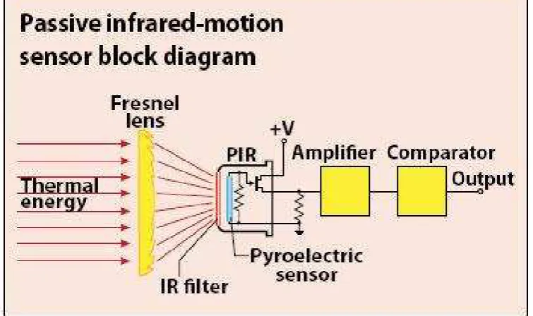
2.2.1 Passive Infrared Sensor
Passive infrared sensors measured the changes in the energy emitted by vehicle and the roads for identify the occupancy status of a parking space [6]. The sensitivity of the sensor is reduced in snow, heavy rain and fog, the sensors are able to be implemented in a multilane environment to measure vehicle speed. And also
certain models are not recommended for presence detection.
Figure 2.1: Passive Infrared Sensor
2.2.2 Active Infrared Sensor
7
Figure 2.2: Active Infrared Sensor
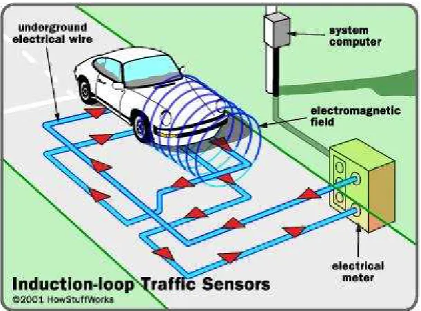
2.2.3 Inductive Loop Detectors
A wire loop of various sizes is called an Inductive Loop Detectors, this sensor using frequencies range from 10 to 50 kHz to send a signal [6]. The oscillation frequency of the inductive loop is directly controlled by the inductance of the loop which changes with vehicle presence.
8
2.2.4 Magnetometer
There are two type of magnetometer which is flux gate magnetometer and search coil magnetometer [6]. The search coil magnetometer are insensitive and are intrusive sensors, meanwhile the flux gate magnetometers are insensitive to weather conditions, proximity is required for accurate detection.
2.2.5 Anistropic Magnetoresistance Sensors
These sensors are simply energized by providing a constant current: Anistropic Magnetoresistance Sensors (AMR), Giant Magnetoresistance Sensors (GMR), magnetic Tunnel Junction Sensors, Extraordinary Magnetoresistance and Ballistic Magnetoresistance. In their research the AMR sensor is for detect a vehicle and its sensitivity to position and orientation has noted.
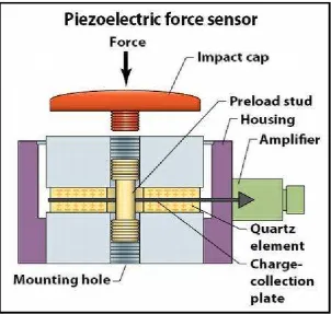
2.2.6 Piezoelectric Sensor
9
Figure 2.4: Piezoelectric Sensor.
2.2.7 Pneumatic Road Tube
When air pressure created, and closes a switch, and then produces the signal when the vehicles pass over the vehicle will be detected [6]. It is temperature sensitive and sometimes in accuracy, and it is easy to maintain and implement.
2.2.8 Weight-in-motion Sensor
This sensor is useful to highway planner, designers and law enforcement agencies that will detect with their weight of the vehicle [6]. Piezoelectric, load cell,