EVALUATION PERFORMANCE OF LOUVERED-FIN COMPACT HEAT EXCHANGER
HASZIL ADHA BIN HASLAN
Laporan ini dikemukakan sebagai
memenuhi sebahagian daripada syarat penganugerahan Ijazah Sarjana Muda Kejuruteraan Mekanikal (Termal-Bendalir)
Fakulti Kejuruteraan Mekanikal Universiti Teknikal Malaysia Melaka
‘Saya/Kami* akui bahawa telah membaca karya ini dan pada pandangan saya/kami* karya ini
adalah memadai dari segi skop dan kualiti untuk tujuan penganugerahan Ijazah Sarjana Muda Kejuruteraan Mekanikal (Termal-Bendalir)’
Tandatangan :……….. Nama Penyelia I:……….. Tarikh :……….
ii
“Saya akui laporan ini adalah hasil kerja saya sendiri kecuali ringkasan dan petikan yang tiap-tiap satunya saya telah jelaskan sumbernya”
iii
ACKNOWLEDGEMENT
Alhamdulillah with His Mercy and Blessings, my greatest gratitude to Allah the Almighty for the chances given to me to complete this project. My first acknowledgement goes to Mr Shamsul Bahari Bin Azraai, my project supervisor. Thanks for his tremendous help, advice, inspiration and unending guidance to me until completing this research. Without him, this project will not exist. The fundamental idea behind this project is his and he never stop from giving me support and encouragement in completing this project. Without his valuable guidance, I would not have been able to achieve the objectivity of this project.
Not forgotten, to my beloved parents, Mr Haslan Bin Hassan and Mrs Nur Aziah Binti Abdul Latif. Your love and caring really touched me. My sister and brother, Haszianaliza Binti Haslan and Hasziq Hafify Bin Haslan. Thanks so much for giving me lifelong encouragement, inspiration and support. May Allah bless all of you.
v
ABSTRAK
vi
LIST OF ABBREVIATIONS xiii
LIST OF APPENDICES xiiii
CHAPTER I INTRODUCTION 1
1.1 Introduction 1
1.2 Objectives 2
1.3 Scopes 2
1.4 Problem Statement 3
CHAPTER II LITERATURE REVIEW 5
2.1 Introduction 5
2.2 Compact Heat Exchanger 6
2.3 Louvered Fin Compact Heat Exchanger 7 2.4 Evaluation Performance of Compact Heat
Exchanger 9
CHAPTER III METHODOLOGY 15
vii
CHAPTER IV RESULTS & DISCUSSION 23
4.1 Introduction 23
CHAPTER VI RECOMMENDATIONS 40
viii
LIST OF TABLES
TABLES TITLE PAGE NO
2.1 Geometrical Parameters of CHE’s 14
ix
LIST OF FIGURES
FIGURES TITLE PAGE NO
1.1 Louvered fin type CHE 2
1.2 An Array of louvered fin with geometrical parameters 3 1.3 Schematic of louvered fin design to be considered 4
2.1 Schematic of Heat Exchanger 5
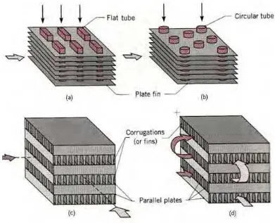
2.2 Compact Heat Exchanger cores (a) Fin-tube (flat tubes, continuous plate fins). (b) Fin-tube (circular tubes, continuous plate fins). (c) Plate-fin (single pass). (d) Plate-fin (multipass)
6
2.3 Car radiator that use louvered fin CHE 7
2.4 Example of louvered fin CHE 8
2.5 Louver directed flow and axial directed flow 8 2.6 Louvered fin with 22˚ louvered angle, 0.81 louvered pitch 14 2.7 Louvered fin with 29˚ louvered angle, 0.81 louvered pitch 14 2.8 Louvered fin with 32˚ louvered angle, 0.81 louvered pitch 14
3.1 Ansys CFX Flow Chart 16
3.2 Definitions of Boundary Condition 20
4.1 An array of louvered fin for the 22° louver angle and 1.30mm louver pitch
24
4.2 Computed Velocity for (a) Lp = 0.81mm (b) Lp = 1.30mm
26
4.3 Computed Temperature (K) for 29° louvered angle and 0.81mm louvered pitch
27
4.4 Computed Temperature (K) for 29° louvered angle and 1.33mm louvered pitch
x
4.5 Static Temperature Contours on fin for (a) θ = 22°, Lp = 1.30mm (b) θ = 29°, Lp = 1.3mm
30
4.6 Fin Temperature against Fin Position 31
4.7 Velocity Vector at the first six arrays for (a) Lp = 0.81mm (b) Lp = 1.30mm
32
4.8 Velocity Vector after the 7th fin for (a) Lp = 0.81mm (b) Lp = 1.30mm
33
4.9 Computed Temperature for (a) θ = 22° (b) θ = 32° 35
4.10 Variation of Fin Temperature 36
xi
LIST OF SYMBOLS
q
= Total Heat Transfer, WU
= Overall Heat Transfer Coefficient, W/m².Km T
= Mean Temperature Different, K
f
= Friction Factorh
= Heat Transfer Coefficient, W/m².Kp
c
= Specific Heat at Constant Pressure, kJ/kG.˚CQ
= Heat Transfer Rate, WLMTD
= Log Mean Temperature Differento
L
= Characteristic Length, m
= Dynamic Fluid Viscosity, kg/m.sv
= Kinematic Fluid Viscosity, m²/sp
Re
d = Reynolds Number Based On Hydraulic Diameter
= Louvered Anglep
xii
p
xiii
LIST OF ABBREVIATIONS
CHE = Compact Heat Exchanger CFD = Computational Fluid Dynamics
etc = Etcetera
xiiii
LIST OF APPENDIXES
BIL TITLE PAGE NO
A RESULT FOR θ = 22°, L P = 0.81MM 41
B RESULT FOR θ = 29°, L P = 0.81MM 42
C RESULT FOR θ = 32°, L P = 0.81MM 43
D RESULT FOR θ = 22°, L P = 1.30MM 44
E RESULT FOR θ = 29°, L P = 1.30MM 45
F RESULT FOR θ = 32°, L P = 1.30MM 46
1
CHAPTER I
INTRODUCTION
This chapter is to introduce the definition of CHE. The purpose, scope and problem statement for this research is also stated here.
1.1 Introduction
Compact Heat Exchanger is commonly used to enhance the heat transfer rate in application that involves with high temperature. Generally there are two types of CHE which are plate-fin type and tube-fin type. CHE is only used for gas or gas-liquid application [1]. Plate Fin Compact Heat Exchanger is widely used in gas-gas application [1]. In this study we will consider plate-fin type with louvered fin.
Nowadays CHE is widely used in various type of industries such as automotive, aeronautics and astronautics, electric and electronic equipment, refrigeration and else. CHE is preferred for application that needs heat exchanger because of its compactness, high-effectiveness, low cost needed, small volume and low in weight [1].
2
There are some parameters that could be change in order to evaluate the performance of CHE. The geometry parameters such as louver pitch, louver angle, fin pitch and tube pitch. Figure 1.1 shows the louvered fin type of CHE.
Figure 1.1: Louvered fin type CHE [2]
1.2 Objectives
The objectives of this study are stated as below:
To study the effect of louver directed flow and axial directed flow around the louvered fin array in the heat transfer enhancement
To visualize the pressure, velocity and temperatures profiles around louvered fin array
To determine the optimum geometry design of louvered fin array for better heat transfer
1.3 Scopes
3
Study the various geometry design in louvered fin array by varying the value of louver angle and louver pitch
Design CFD Louvered fin geometry using CFX software (Design Modeler) Simulate air flow through louvered fin array
Study the effect of flowing air through the louvered fin array
1.4 Problem Statement
The problem that we have to consider here is by comparing the performance of this type of CHE by varying geometrical parameter such as louvered angle and louver pitch.
Figure 1.2 shows an array of louvered fin with geometrical parameters in CHE. This study will only focus the effects of varying the value of louver angle and louver pitch.
The flow phenomena of the air will be either axial directed flow or louver directed flow or both. The effects of the flow phenomena will be discussed to determine the heat transfer efficiency between the flowing air and the louvered fin array. The value of fin pitch will remain constant at 2.11mm.
4
Figure 1.3 shows the schematic of louvered-fin design. The studied air will be flowing into the louvered fin array from the inlet and will be drawn out through the outlet. The symmetry part will be transform later in CFX Post to view the real simulation of the fin array.
Figure 1.3: Schematic of louvered-fin design to be considered [2]
5
CHAPTER II
LITERATURE REVIEW
This chapter will discuss about all the equations, theory, past studies and parameters used in this research.
2.1 Introduction
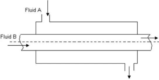
Heat exchanger is a device that efficiently transfers or exchange heats from a fluid to another fluid without any contact between those two [4]. Figure 2.1 shows the simplest heat exchanger.
Figure 2.1: Schematic of Heat Exchanger
6
2.2 Compact Heat Exchanger
The definition of CHE is based on heat exchanger definition but in CHE, compact is added. And so, based on heat exchanger definition the definition of CHE will be; a heat exchanger that is compact which means it has small volume, small size and also low in weight. CHE are typically used when a large heat transfer surface area per unit volume is desired or at least one of the fluids is a gas [5]. A CHE can reach an area density higher than 500m2/m3 with respect to 100 m2/m3 -
200 m2/m3 of the shell and tube heat exchanger [6]. There are generally two types of
CHE which are plate-fin type or tube-fin type [1]. Figure 2.2 shows the example of plate-fin type CHE.
7
CHE appliances that are commonly used are car radiator or automotive radiator. In this case of CHE, the heat exchanger is used to cool the engine as the engine is heated because of the combustion process. Because of the combustion process of the engine, the engine’s temperature will later increased and to avoid overheating of the engine, CHE is used where in this case, fluid in the CHE is commonly called as coolant and this coolant will move around the engine and cooled it down. The coolant is cooled because of the air flowing through the geometry of the CHE act as a cooling fluid to the fin array. Figure 2.3 shows the car radiator that use louvered fin CHE.
Figure 2.3: Car radiator that use louvered fin CHE [7]
Coolant will enter the tube from the coolant inlet tank and as the coolant moves through the tube, heat transfer happened between the coolant and air. As a result of this heat transfer process, the coolant will later being cooled down and exit to the coolant outlet tank.
2.3 Louvered Fin Compact Heat Exchanger
8
Figure 2.4: Example of louvered fin CHE [3]
When this louvered fin was firstly introduced, it was believed that increased heat transfer was due to added turbulence initiated by flow through the louvered array [3]. But this theory was later proved wrong by the visualization studies on scaled up louver design [3]. It was observed that as air passes through the louver, the flow resulted in two distinct flow directions to be classified: axial (or duct) directed flow and louver flow. Axial flow occurs when the flow maintains the directions of the inlet flow. Louver directed flow occurs when the flow was aligned parallel to the louver [3]. Figure 2.5 shows clearly the two directions indicated in the louvered fin cross section.
Figure 2.5: Louver directed flow and axial directed flow [3].
9
2.4 Evaluation Performance of Compact Heat Exchanger
There are generally two ways in evaluating the performance of CHE which are by numerical predictions using Computational Fluid Dynamic or by experimental measurement where direct experiment was done in order to obtain data needed for the performance calculation. For this research, CFD method is used in evaluating the performance of CHE. Software used for this simulation is Ansys CFX.
2.4.1 Computational Fluid Dynamic
CFD is a branch of fluid dynamics where it is use widely to solve and analyze problem that involve with fluid flow and heat transfer using numerical method and algorithm [8]. Supercomputer or computer that works together in parallel is used to solve millions of equation required to simulate interaction of fluid and gasses. However, whatever value we get from CFD is only approximate solutions until the results have been validated by experimental results. The basic of solving any CFD equations is by using the Navier-Stokes equations, which defines any single-phase fluid flow. These equations will be simplified later by removing terms describing viscosity to yield the Euler equation. Later, by removing terms describing vorticity it will yields full potential equations. Finally these equations can be linearized to yield the linearized potential equation [8].
2.4.2 Log Mean Temperature Different
![Figure 1.1: Louvered fin type CHE [2]](https://thumb-ap.123doks.com/thumbv2/123dok/651557.79459/17.595.224.411.164.308/figure-louvered-fin-type-che.webp)
![Figure 1.2: An Array of louvered fin with geometrical parameters [3]](https://thumb-ap.123doks.com/thumbv2/123dok/651557.79459/18.595.155.521.531.671/figure-array-louvered-fin-geometrical-parameters.webp)
![Figure 1.3: Schematic of louvered-fin design to be considered [2]](https://thumb-ap.123doks.com/thumbv2/123dok/651557.79459/19.595.142.512.176.342/figure-schematic-of-louvered-fin-design-to-considered.webp)
![Figure 2.3: Car radiator that use louvered fin CHE [7]](https://thumb-ap.123doks.com/thumbv2/123dok/651557.79459/22.595.179.497.258.420/figure-car-radiator-use-louvered-fin-che.webp)
![Figure 2.4: Example of louvered fin CHE [3]](https://thumb-ap.123doks.com/thumbv2/123dok/651557.79459/23.595.140.508.505.633/figure-example-of-louvered-fin-che.webp)
