UNIVERSITI TEKNIKAL MALAYSIA MELAKA
DEVELOPMENT OF CONTROLLER FOR FRONT
COVER ASSEMBLY STATION FOR FLEXIBLE
MANUFACTURING SYSTEM USING PLC
Thesis submitted in accordance with the partial requirements of the Universiti Teknikal Malaysia Melaka for the
Bachelor of Manufacturing Engineering (Robotic & Automation)
By
MOHD ZUWAIRY BIN ROSDI
DECLARATION
I hereby, declare this thesis entitled “Development Of Controller For Front Cover Assembly Station For Flexible Manufacturing System Using PLC ” is the result of my
own research except as cited in the references.
Signature : ……….
Author‟s Name : Mohd Zuwairy bin Rosdi
APPROVAL
This thesis submitted to the senate of UTeM and has been accepted as partial fulfillment of the requirements for the degree of Bachelor of Manufacturing Engineering
(Robotic And Automation). The members of the supervisory committee are as follow:
……… Supervisor
ACKNOWLEDGEMENTS
Alhamdulillah, I‟m grateful that by the power of Allah, Most Gracious, Most Merciful, I managed to complete this project. I also want to thank my parents, who taught me the value of hard work by their own example. Both of them are my source of inspiration that lead me to working hard in gaining knowledge. I also would like to share this moment of happiness with all my friends that had help me in completing this project in one way or another.
ABSTRACT
ABSTRAK
Sistem Pembuatan Fleksibel (FMS) telah diberi pengiktirafan sebagai satu revolusi industri dalam abad ke-21. Ianya digunakan secara universal untuk kaedah pengawalan sistem berautomasi, kawalan proses dan sistem pembuatan, dan pengawal automasi yang biasa digunakan dalam FMS adalah Kawalan Logik Boleh Aturcara (PLC). Geganti pengeluaran dibina dalam PLC direka dengan pelbagai sambungan dalaman sebagai tambahan kepada sambungan pengeluaran di sebelah luar. Untuk membangunkan pengawal automasi dan menghasilkan mekanisme pemasangan bingkai hadapan skrin LCD bagi projek ini, kawalan logik program SIMATIC S7 digunakan sebagai medium pengawal untuk mengawal stesen pemasangan. Program yang akan dibina berfungsi untuk mengawal turutan proses dan pergerakan perkakasan dalam proses pemasangan skrin LCD. Rajah tetangga dipilih sebagai bahasa pengaturcaraan untuk menghasilkan turutan dalam PLC. Terdapat empat fasa utama yang digunakan dan ditekankan melalui kaedah carta alir bagi memastikan objektif dapat dicapai. Proses pengaturcaraan kawalan bagi projek ini akan diusulkan sebagai keputusan, seterusnya susulan cadangan daripada pemerhatian dan analisis program mengakhiri laporan bagi pembangunan projek ini.
TABLE OF CONTENTS
1.1. Problem Statements ……….
1.2. Objectives/ Outcome ………
1.3. Scope ………
1 4 4 5
2.2.2.1 Ball Bearings………..
3.1.1 Requirement Planning Phase………. 3.1.2 Research of Project Phase……….. 3.1.3 Design of Project Phase………. 3.1.4 Implementation Phase………..
3.2 Project Flow Chart……… ………...
3.2.4 Project Implementation………
6. CONCLUSION AND RECOMMENDATION………...
6.1 Weaknesses and Strengths………
6.2 Recommendation and Suggestion……….
LIST OF FIGURES
Figure 1.1: Schematic of a PLC
Figure 2.1: Example of FMS in industry Figure 2.2: AC motor (Siemens motor) Figure 2.3: Rotor
Figure 2.4: Stator
Figure 2.5: Motor enclosure (Siemens motor) Figure 2.6: DC motor
Figure 2.7: DC motor operation Figure 2.8: Servo motor
Figure 2.9: Servo motor movement Figure 2.10: Stepper motor
Figure 2.11: Ball bearing Figure 2.12: Linear bearings Figure 2.13: Ball screw
Figure 2.14: Flexible coupling
Figure 2.15: Basic component of pneumatic system Figure 2.16: Valves
Figure 2.17: Pneumatic cylinders
Figure 2.18: Suction cup
Figure 2.19: Basic elements in PLC
Figure 2.20: PLC diagram
Figure 2.21: Example of Ladder diagrams
Figure 2.22: PLC operation diagram
Figure 2.23: Basic elements of a relay diagram
Figure 2.24: Condition and instruction in relay diagram Figure 2.25: Symbol of counter
Figure 2.26: Counter in ladder diagram Figure 2.27: Symbol of timer
Figure 2.28: Timer in ladder diagram Figure 3.1: Flow chart for planning stage Figure 3.2: Front Cover assembly station Figure 3.3: Flow of the sequence movement Figure 4.1: Housing of linear bearing Figure 4.2: Cover for ball bearing housing Figure 4.3: Mounting for motor B
Figure 4.4 : Ball bearing housing (X-axis) Figure 4.5: Linear bearing housing (X-axis) Figure 4.6: Wiring diagram of PLC
Figure 4.7: Wiring board for PLC Figure 4.8: PLC ladder diagram
Figure 5.1: Functional block diagram network 1 Figure 5.2: Functional block diagram network 2 Figure 5.3: Functional block diagram network 3 Figure 5.3: Functional block diagram network 4 Figure 5.3: Functional block diagram network 5 Figure 5.3: Functional block diagram network 6 Figure 5.3: Functional block diagram network 7 Figure 5.3: Functional block diagram network 8 Figure 5.3: Functional block diagram network 9 Figure 5.3: Functional block diagram network 10 Figure 5.3: Functional block diagram network 11 Figure 5.3: Functional block diagram network 12 Figure 5.3: Functional block diagram network 13
LIST OF TABLES
Table 4.1: List of inputs 71
Table 4.2: List of outputs 73
LIST OF ABBREVIATIONS
Programmable Logic Control Musculoskeletal Disorders Liquid Crystal DisplayTOF TMH TMS TMRAF RTO TMRA BCD AMC
- - - - - - - -
Timer Off Delay High Speed Timer Super High Speed Timer Accumulating Fast Timer Retentive Timer
Accumulating Timer Binary Code Decimal
CHAPTER 1
INTRODUCTION
In the middle of the 1960s, market competition became more intense. During 1960 to 1970 cost was the primary concern. Later quality became a priority. As the market became more and more complex, speed of delivery became something customer also needed. A new strategy was formulated: Customizability. The companies have to adapt to the environment in which they operate, to be more flexible in their operations and to satisfy different market segments (customizability). Thus the innovation of FMS became related to the effort of gaining competitive advantage.
First of all, FMS is a manufacturing technology. Secondly, FMS is a philosophy. "System" is the key word. Philosophically, FMS incorporates a system view of manufacturing. The buzz word for today‟s manufacturer is "agility". An agile manufacturer is one who is the fastest to the market, operates with the lowest total cost and has the greatest ability to "delight" its customers. FMS is simply one way that manufacturers are able to achieve this agility.
incredibly complex software. There were only a limited number of industries that could afford investing in a traditional FMS as described above.
Currently, the trend in FMS is toward small versions of the traditional FMS, called flexible manufacturing cells (FMC). Today two or more CNC machines are considered a flexible cell and two ore more cells are considered a flexible manufacturing system. Thus, a FMS consists of several machine tools along with part and tool handling devices such as robots, arranged so that it can handle any family of parts for which it has been designed and developed.
The manufacturing equipment on the shop floor is grouped into manufacturing cells with a programmable controller (most likely) providing direct monitoring, coordination, and control of activities that take place on the equipment within a cell.PLC has been gaining popularity on the factory floor as a programmable controller and will probably remain predominant for some time to come. Most of this is because of the advantages they offer such as cost effective for controlling complex systems, flexible and can be reapplied to control other systems quickly and easily, computational abilities allow more sophisticated control, trouble shooting aids make programming easier and reduce downtime and also reliable components make these likely to operate for years before failure.
rewired for the new application. This was inflexible and time consuming, it restricted the production scheduling of a factory and made changing of product difficult.
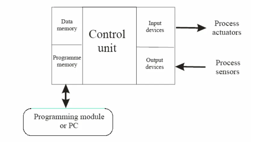
Figure 1.1: Schematic of a PLC
1.1 Problem Statements
In a small company, there are still some of the assembling processes that still being conducted manually. Manual assembling process can take a long time because human will usually be tired doing the same task over and over again. This will result to inefficient work condition. The repetition of these works over long period of time can cause the workers to experiencing lower back pain and in some cases of musculoskeletal disorders (MSDs). In some serious cases, this type of injury can cause the operator to be paralyzes.
Today we also see that the trend toward automation of production equipment is putting great demands on people. The manufacturers have worked to increase productivity, capability, reliability and flexibility by using technologies. In order to achieve these are making use more and more automation in manufacturing. The problem are typically industrial processes in manufacturing where the cost of developing and maintaining the automation system is high relative to the total cost of the automation, and where changes to the system would be expected during its operational life.
1.2 Objective / Outcome
The main objective of this project is to develop the programming which controls the sequences of operation for the assembly station using PLC. Additional objective of this projects are:-
a) To do modification in mechanical parts to get complete structure for assembly station.
1.3 Scope
In order to design successful FMS workstation system, scopes are required to assist and guide the development of the project. The scope should be identified and planned to achieve the objective of the project successfully on the time. The scopes for this project are:
Assembly station:
Learn the basic operation
Investigate the structure of input output and pneumatic components involved in this station.
Identified all connection and relationship between station and PLC.
PLC
Learn and familiarize the PLC program that will be use in this project.
Investigate and describe the function of each device such as the counter and pulse for motor driver.
Study the wiring and connection between input output and the PLC.
Study ladder diagram and block diagram function and learn how to interpret to input and output for assembly station.
Identified and learn how to minimize the program language to be a simple network program.
CHAPTER 2
LITERATURE REVIEWS
2.1 FMS
2.1.1 Introduction
2.1.2 History of FMS
At the turn of the century FMS did not exist. There was not a big enough need for efficiency because the markets were national and there was no foreign competition. Manufacturers could tell the consumers what to buy. Henry Ford is quoted as saying “people can order any color of car as long as it is black.” This was the thinking of many big manufacturers of the time. After the Second World War a new era in manufacturing was to come. The discovery of new materials and production techniques increased quality and productivity. The wars end open foreign markets and new competition. Now the market focused on consumer and not the manufacturer. The first FMS was patent in 1965 by Theo Williamson who made numerically controlled equipment. Examples of numerically controlled equipment are like a CNC lathes or mills which is varying types of FMS. In the 70‟s manufacturers could not stay to date with the ever-growing technological knowledge manufacturers competitors have, so FMS became mainstream in manufacturing. In the 80‟s for the first time manufacturers had to take in consideration efficiency, quality, and flexibility to stay in business (Maleki, 1991).
2.1.3 Benefits of Flexible Manufacturing
Below is a list of benefits for using FM systems:- Short-term Changes
a) Engineering changes, b) Processing changes,
c) Machine unavailability, and d) Cutting tool failure.
Long term Changes
a) Changing product volumes, b) Different part mixes, and c) New Product additions.
For many manufacturers and industrial companies, FMS is expensive to purchase and install. For the most part, to install FMS is a multimillion dollar investment. Besides the installation of the FMS the training of the people working on the FMS can be complex. So because of the cost of these systems the manufactures that use them are very specialized (Dunlap, 1984).
2.1.4 Development of FMS
Several actions must be decided on before you can have a FMS. These actions include. a) Selecting operations needed to make the product.
b) Putting the operations in a logical order. c) Selecting equipment to make the product. d) Arranging the equipment for efficient use.