Development of Ultra-Wideband (UWB)
Horn Antenna Using Approximation Method
M.A.Othman
1,2, M.Z.A.A.Aziz
1, N.Saysoo
1, A.R.Othman
11
Centre for Telecommunication Research and Innovation Fakulti Kej. Elektronik dan Kej. Komputer
Universiti Teknikal Malaysia Melaka 76100, Durian Tunggal, Melaka, Malaysia
2
Photonics and RF Engineering Group, Division of Optic and Electrical System Department of Electrical and Electronic Engineering
University of Nottingham, NG7 2RD, Nottingham, UK
[email protected],2, [email protected], [email protected], [email protected]
Abstract—This paper presents a design of an ultra wide-band
(UWB) horn antenna for microwave imaging radar system. The key purpose of the study is to design a horn antenna which is used in medical imaging system. The proposed antenna operates within 3.1-10.6 GHz as it is the band allocated for medical industry usage. The antenna known as a directional antenna which is supported by rectangular waveguide. The horn antenna is purposely chosen to design in order to increase the directivity of the antenna within 15-20 dB and achieve higher gain and wider bandwidth as possible. This horn antenna is capable to produce return loss as minimum as possible. The antenna is designed and simulated using CST Microwave Studio. The simulation results show that the pyramidal horn antenna structure exhibits low VSWR as well as good radiation pattern over 3.1-10.6 GHz frequency band.
Keywords: Ultra wide-band antenna, horn antenna, VSWR, microwave radar.
I. INTRODUCTION
As an emerging technology, Ultra Wide Band (UWB) communications system provides a very different approach to wireless technologies compared to conventional narrow band systems, which brings huge research interests in it. Because of this, UWB has many potential applications to be researched. One of the promising application areas is in medicine. Some unique features of UWB make it very suitable for medical areas [1]. Ultra-wideband (UWB) radio is an emerging technology with some unique attractive features which are combined with researches in other fields such as wireless communications, radar, and medical engineering fields. Formally before 2001, UWB's application is limited mainly in military areas. However, since 2002, Federal Communications Commission (FCC) has gradually allowed the commercial usage of these bandwidths, which makes it possible that every common people could benefit the UWB features. FCC regulate that the frequency for the UWB technique is from 3.1GHz to 10.6GHz in America [1].
It is known that the UWB pulse is generated in a very short time period (sub-nano second). So it has spectrum below the allowed noise level. This feature makes it possible to get
Gigabit per second (Gbps) speed by using 10GHZ spectrum. So UWB is suitable to be used for high-speed over short distances [2]. UWB is often deemed as a possible alternative to remote sensing and imaging. Compared with X-ray imaging, UWB radar probes use non-ionizing electromagnetic waves which proved to be harmless to human body. Moreover, the UWB radar has very low average power level and is very power efficient. Thus is suitable to be a potentially cost effective way of human body imaging, especially in real time imaging. By 1999, many works have begun for UWB medical applications in cardiology, obstetrics, breath pathways and arteries [3]. Besides, UWB has many other applications such as high resolution penetrating radar, hidden object detection system, EMC experiments, free-space time-domain (FTD) measurement systems and feed for reflectors [4].
There are a lot of commercialized UWB antennas in the market nowadays. The conical antenna suspended over a large metal ground plane is the preferred antenna for transmitting known transient electro-magnetic waves. This type of antenna is used by NIST as their reference standard transient transmitting antenna. This antenna radiates an E-M field that is a perfect replica of the driving point voltage waveform. TEM horns are the most preferred metrology receiving antenna for making a direct measurement of transient E-M fields [5]. The TEM horn antenna is basically an open-ended parallel plate transmission line. It is typically built using a taper from a large aperture at the receiving input down to a small aperture at the coax connector output. A monopole antenna is the most fundamental building block antenna for most antenna designs. It is the quarter wave whip antenna above an infinite ground plane. The monopole antenna is sometimes used as a simpler version of the conical antenna for transmitting UWB signals which are similar in wave shape to the driving point voltage. However, its radiated fields are not as uniform as those for the conical antenna. Its driving point impedance is not constant, but rises as a function of time. This leads to distortion of the radiated E-M fields [6].
The significant feature of UWB is the low electromagnetic radiation due to the low radio power pulse less than -41.3dB in
2012 IEEE Symposium on Wireless Technology and Applications (ISWTA), September 23-26, 2012, Bandung, Indonesia
indoor environment. The low radiation has little influence on the environment, which is suitable for hospital applications. Furthermore, the low radiation is safe for human body, even in the short distance, which makes it possible to apply UWB to the clairvoyant equipments.
A few types of design methods are identified from literature review as a milestone for the project. Typical examples of wideband antennas used for pulse radiation include resistively loaded monopoles, dipoles, bow-tie antennas, and various forms of horn antennas [7] - [11]. It has been noted that the bandwidth of horn antennas can be increased significantly by adding metallic ridges to the waveguide and flared sections [12]. Numerical and experimental investigations of pyramidal horn antennas with double ridges have been reported previously [13]. This type of antenna is commercially available with an operational frequency band of 1–18 GHz. However, the large dimensions and high cost of these antennas make them unsuitable for medical imaging applications.
II. METHODOLOGY
The antenna is designed using approximation method of gain. An approximation value of gain 15 dB is used to design the antenna as the gain determines the overall size of the horn antenna.
First of all, a rectangular waveguide should be design as to precede the basic horn antenna structure. In order to initiate the basic design, the feeding waveguide is chosen according to the frequency range of interest. The mid frequency is set to be 7 GHz. The inner dimension is chosen to be 1.372 x 0.622 inch2 which is closer to WR-137 that supports the frequency range of 5.85-8.20 GHz (C-Band). The aperture dimension a1 x b1 has
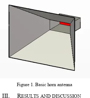
been calculated under the same length of E-plane and H-plane, which means under the equal beam width in E and H planes. According to the [14], the gain determined the length as well as the size of the antenna. The higher gain contributes to larger size of antenna. In that case, the gain 15 dB is selected approximately to keep the antenna dimensions small. Figure 1 below shows the design of basic horn antenna.
Figure 1. Basic horn antenna
III. RESULTS AND DISCUSSION
Once the design completed, the antenna is simulated through the CST software. The results of parameters that obtained from simulation are the frequency, return loss, voltage
standing wave ratio (VSWR), directivity, gain, bandwidth and radiation pattern. The results shown below are the most significant figure that obtain from simulation which determine the strength of the signal transmitted through the horn antenna.
Figure 2. Return loss vs frequency
The Figure 2 above refers to the S11 parameter which means
the return loss of the horn antenna. The amount of return loss from 3 GHz to 11 GHz is below -10 dB and it indicates that the strength of signal received during the transmission is stable enough to obtain a clear picture of data. In other words, almost 90% of signal transmitted through the antenna had been received with minimum loss. This is endorsed by the VSWR calculated during the simulation.
Figure 3. VSWR vs frequency
The Figure 3 above shows the amount of voltage standing wave ratio which is calculated through simulation. The value of VSWR shown is 1.84 which is less than 2 and it is considered fairly well for the signal transmission with lower attenuation.
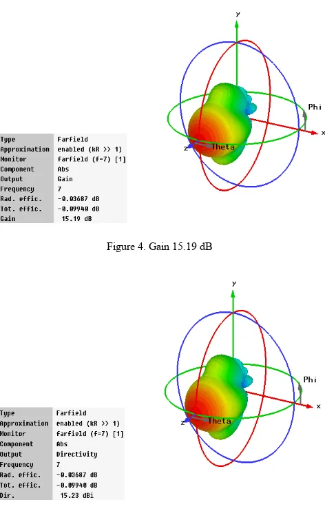
Antenna gain is the most important fundamental property of an antenna. An antenna has good matching but it will be useless if it does not radiate. An antenna gain is a measurement of how good an antenna radiate or receives power it is given or subjected to. Figure 4 shows the gain 15.19 dB of the horn antenna through simulation. It is increased by 0.19 dB from approximated gain with the efficiency of software simulation. The gain produced must be around 15 dB as to achieve the target of approximation and to ensure the size of the horn
This project have been sponsored by Universiti Teknikal Malaysia Melaka Short Term Grant - PJP / 2011 / FKEKK (38C) S935
2012 IEEE Symposium on Wireless Technology and Applications (ISWTA), September 23-26, 2012, Bandung, Indonesia
antenna is small. The gain 15.19 dB is good enough for the antenna that will be used in medical imaging system. The ability of the signal to penetrate into the human body is influenced by the power gain of the antenna.
Figure 4. Gain 15.19 dB
Figure 5. Directivity 15.23 dBi
The directivity refers to the region where the strongest emission of the signal radiated and the maximum gain produced. The directivity obtained from simulation is 15.23 dBi respected to isotropic antenna. The directivity is always proportional to the gain. As the gain increase the directivity also increases. The higher directivity exhibits the more stronger signal radiated through the aperture of the horn antenna.
Radiation pattern are graphical representation of electromagnetic power distribution in free space. This pattern also can be considered to be representative of the relative field strengths of the field radiated by the antenna. The figure above shows the radiation pattern of horn antenna which consists of main lobe, side lobes and back lobe. The magnitude of the main lobe obtained is 15.2 dBi while side lobe is -11.3 dB. It shows that the main lobe is much more larger than side lobes and back lobe. It means that more power are radiating through
main lobe compared to other directions. The narrower main lobe indicates that the higher intensity of radiation.
Figure 6. Radiation Pattern at 7 GHz
IV. CONCLUSION AND FUTURE WORKS
According to the results above, the designed horn antenna is considered stable and suitable to be operated within given frequency range of 3.1 – 10.6 GHz. The lower return loss and voltage standing wave ratio assures that the signal radiated is almost in equilibrium state. It means that the signal transmitted and the signal received is almost perfect with lower attenuation. The higher gain obtained proves that the antenna preferentially radiate in particular direction with higher radiated power. The higher directivity attained indicates the strengthen region where the maximum gain accumulated. In addition, the radiation pattern shown in polar form considered good with the main lobe is larger than side lobes and back lobe.
As for the future works, the horn antenna will be improved in terms of its structure. In order to support the given frequency range and to increase the gain and directivity, an exponential tapered ridges will be added inside the aperture of the horn antenna. Besides, the VSWR also able to be reduced by using the ridges inside the antenna. The lower VSWR improves the return loss and signal transmission. The ridges will be designed on both of the E-planes and H-planes inside the antenna. It will make sure the antenna propagate its signal more accurately and concentrated into one direction with strongest emission. As the radiation become stronger and narrower, the detection and reflection of an antenna will be more precise to be applied in medical imaging system.
The ridges are designed using the method explained in [14]. The author has been modified the antenna to be operated within 2 – 18 GHz by designing double ridges inside the antenna. The tapered part varies the impedance of the guide from 50 Ω at the feeding point to 377 Ω at aperture of the antenna. The impedance variation in the tapered part is as calculated by equation given below:
Z(y) = z0eky, (0 ≤ y ≤ L) (1) 2012 IEEE Symposium on Wireless Technology and Applications (ISWTA), September 23-26, 2012, Bandung, Indonesia
Where y is distance from the waveguide aperture and L is the axial length of the antenna opening. The k is calculated as follow:
k =
L
ln
(2)
where the Z0 and ZL are the characteristic impedances of
rectangular waveguide and free space respectively.
REFERENCES
[1] Ben Allen, Tony Brown, Katja Schwieger, Ernesto Zimmermann, Wasim Malik, David Edwards, Laurentvry, Ian Oppermann, “Ultra Wideband: Applications, Technology and Future perspectives”, International Workshop on Convergent Technologies (IWCT) 2005.
[2] Xu Yong, Lu Yinghua, Zhang Hongxin, Wang Yeqiu, " An Overview of Ultra-Wideband Technique Application for Medial Engineering", 2007 IEEE/ICME International Conference on Complex Medical Engineering(CME), Beijing, May 2007.
[3] T. E. McEwan, "Body monitoring and imaging apparatus and method," US Patent No.5,573,012, Issued on November 12, 1996.
[4] A. R. Mallahzadeh and F. Karshenas, “Modified TEM Horn Antenna For Broadband Applications”, Progress In Electromagnetics Research, PIER 90, 105-119, 2009.
[5] R. Johnk & A. Ondrejka, "Time-Domain Calibrations of D-Dot Sensors", NIST Tech. Note 1392, NIST, Boulder, CO, Feb. 1998.
[6] S. Ramo & J. Whinnery, Fields & Waves in Modern Radio, J. Wiley, New York, 2ed edition, 1962, pp. 406-408.
[7] T. T.Wu and R.W. P. King, “The cylindrical antenna with nonreflecting resistive loading,” IEEE Trans. Antennas Propagation, vol. AP-13, pp.369–373, May 1965.
[8] J. G. Maloney and G. S. Smith, “A study of transient radiation from the Wu-King resistive monopole FDTD analysis and experimental measurements,” IEEE Trans. Antennas Propagat., vol. 41, pp. 668– 676,May 1993.
[9] S. C. Hagness, A. Taflove, and J. E. Bridegs, “Three-dimensional FDTD analysis of a pulsed microwave confocal system for breast cancer detection: design of an antenna-array element,” IEEE Trans. Antennas Propagation, vol. 47, pp. 783–791, May 1999.
[10] D. W. van der Weide, “Planar antennas for all-electronic terahertz systems,” J. Opt. Soc. Amer. B, vol. 11, pp. 2553–2560, 1994.
[11] K. L. Shlager, G. S. Smith, and J. G. Maloney, “Accurate analysis of TEM horn antennas for pulse radiation,” IEEE Trans. Electromagnetic Compatibility, vol. 38, pp. 414–423, Aug. 1996.
[12] K. L. Walton and V. C. Sundberg, “Broadband ridged horn design,” Microwave J., vol. 4, pp. 96–101, Apr. 1964.
[13] B. M. Notaros, C. D. McCarrick, and D. P. Kasilingam, “Two numerical techniques for analysis of pyramidal horn antennas with continuous metallic ridges,” in Proc. IEEE Int. Symp. Antennas Propagation Dig., vol. 2, Boston, MA, 2001, pp. 560–563.
[14] Constantine.A.Balanis, “Antenna Theory: Analysis and Design”, John-Wiley and Sons Publication, 2005, pp -739
2012 IEEE Symposium on Wireless Technology and Applications (ISWTA), September 23-26, 2012, Bandung, Indonesia