DESIGN AND DEVELOP TES SPLIT UNIT OF AIR CONDITIONING SYSTEM
NOR EFFYZA BT ROSLAN
This Report Is Submitted In Partial Fulfillment of Requirement for the Bachelor
Degree
of Mechanical Engineering (Thermal Fluid)
Faculty of Mechanical Engineering
Universiti Teknikal Malaysia Melaka
“I admit to have read this report and it has followed the scope and quality in Partial
Fulfillment of Requirement for the Degree of Bachelor of Mechanical Engineering
(Thermal Fluid)”
Signature : ...
Supervisor Name : ENCIK. SAFARUDIN GHAZALI
HERAWAN
ii
AGREEMENT
“I agree that this report is my own work except for some summaries and information
which I have already stated”
Signature : ………
Name : NOR EFFYZA BT ROSLAN
Untuk Ibu Dan Ayah Tersayang…
Hanya Engkau Sahaja Ilham Hidupku…
Akan Ku Buktikan Kepadamu…
4
ACKNOWLEDGEMENT
First of all, I would like to express my gratitude to Universiti Teknikal Malaysia
Melaka (UTeM), for giving me this valuable opportunity to undergo “Projek Sarjana
Muda ”. Without this opportunity, I will never gain any experience and knowledge about
the works which related to mechanical engineering.
Thanks a lot also especially to my main supervisor Mr. Safarudin Ghazali
Herawan who always guides me and teaches me in this semesters. I really appreciate the
kindness of him in exposing me to the world of engineering, the duties and the
responsibilities as a lecturer even though they very busy with their own work.
I would also like to thank to all lecturers Faculty of mechanical engineering and
all staff and technicians, who give advice to me about the project that I done. Not
forgetting also to thank all friends who always keen to help when I faced any problems.
Thanks a lot also to Universiti Teknikal Malaysia Melaka (UTeM), because guide me
regarding to “projek Sarjana Muda ” from initial until end of the Project.
Lastly, I will always remember all the knowledge and this great that I gained
during undergo “projek Sarjana Muda ”. Without the helps from all of them, I believe
ABSTRACT
Nowadays, most of the building were used the air conditioning refrigeration
systems for a cooling down the temperature inside of the room. However, the air
conditioning refrigeration systems is using more electric consumption. In generally, cool
storage technology can be used to significantly reduce energy costs by allowing energy
intensive, electrically driven cooling equipment to be predominantly operated during
off-peak hours when electricity rates are lower. Thermal energy storage may refer to a
number of technologies that store energy in a thermal reservoir for later reuse. Five step
of methodology was used in experiment such as sketch the split unit system, prepare
material or components are needed, install the component, recheck the component and
run the system. Thermal energy storage had been created in order to saving energy
consumption especially on electric power. The result of electric consumption for thermal
energy storage is 0.3kW compare than conventional air conditioning which 1.232kW is
needed for operate the system. Coefficient of performance of air conditioning can be
determined by power use and capacity of ice in the storage. Where, value of coefficient
of performance will increase with increasing of power pump, rate capacity of air
6
ABSTRAK
Pada masa kini, kebanyakkan bangunan adalah menggunakan sistem
penyejukkan penyaman udara untuk menyejukkan suhu di dalam bilik. Bagaimanapun,
sistem penyejukkan penyaman udara menggunakan lebih tenaga elektrik. Secara
umumnya, teknologi penyimpanan tenaga sejuk boleh digunakan untuk mengurangkan
kos tenaga dengan membenarkan tenaga intensif, kelengkapan penyejukkan elektrik
dipandu menjadi lebih banyak beroperasi semasa waktu tidak sibuk apabila kadar
elektrik adalah rendah. Penyimpanan tenaga haba boleh dirujuk kepada nombor dari
teknologi iaitu penyimpanan tenaga dalam takungan haba untuk digunakan semula
kemudian. Lima cara dari langkah-langkah digunakan dalam eksperimen seperti lakaran
sistem pengasingan unit, penyediaan bahan atau komponen yang diperlukan, memasang
komponen, menyemak semula komponen dan sistem dijalankan. Penyimpanan tenaga
haba adalah dicipta supaya untuk menjimatkan penggunaan tenaga terutamanya kuasa
elektrik. Keputusan penggunaan elektrik untuk penyimpanan tenaga haba adalah 0.3kW
dibandingkan dengan penyaman udara biasa yang mana 1.232kW diperlukan untuk
sistem beroperasi. Pekali perlaksanaan dari penyaman udara boleh dikira dari kuasa
yang digunakan dan muatan ais dalam simpanan. Di mana, niai pekeli perlaksanaan akan
meningkat dengan peningkatan kuasa pam, kadar muatan dari penyaman udara dan
TABLE OF CONTENTS
CHAPTER TITLE
AGREEMENT
PAGE
ii
DEDICATION iii
ACKNOWLEDGEMENT iv
ABSTRACT v
ABSTRAK vi
TABLE OF CONTENTS vii
LIST OF TABLES xi
LIST OF FIGURES xii
LIST OF SYMBOLS xiv
CHAPTER 1 INTRODUCTION 1
1.1 Background of Study 1
1.2 Objective 2
1.3 Scope 2
8
CHAPTER 2 LITERATURE REVIEW 4
2.1 Introduction TES 4
2.2 Physical Principal TES 5
2.3 TES System 7
2.4 TES Design 7
2.5 Type of TES 9
2.5.1 Sensible Heat 9
2.5.2 Liquid Storage Media 11
2.5.3 Solid Storage Media 13
2.6 Air Conditioning 14
2.7 Air Conditioning System and Application 16
2.7.1 Functions of Air Conditioning System 17
2.8 Split System 19
2.9 Refrigerant and Heat Pump 22
2.10 Coefficient of Performance (COP) and 24
Power Consumption
2.11 Inside Design Condition 25
2.11.1 Cold Storage 26
2.11.2 Industrial Air Conditioning 26
2.11.3 Comfort Air Conditioning 26
CHAPTER 3 METHODOLOGY 27
3.1 Study procedure 27
3.2 Experiment Procedure 28
3.2.1 Sketch the split unit system 29
3.2.2 Prepare material or
components are needed 29
3.2.3 Install the components 30
3.2.4 Recheck the components 30
3.2.5 Run the system 31
3.3.1 Storage 32
3.3.2 Motor and Pump 32
3.3.3 Evaporator 33
3.3.4 Chiller water 34
3.3.5 Glycol 34
3.3.6 Condenser 35
3.37 Piping system 36
3.3.8 Thermocouples 36
3.4 Properties of Moist Air 37
3.4.1 Psychometric Properties 37
3.4.2 Specific Humidity or humidity Ratio 37
3.4.3 Relative Humidity 38
3.4.4 Enthalpy of Moist Air 39
3.4.5 Wet Bulb Temperature (WBT) 40
3.4.6 Humid Specific Heat 42
3.5 Psychrometry of Air-Conditioning Process 43
3.5.1 Mixing Process 43
3.5.2 Mixing with Condensation 45
3.5.3 Basic Process in Conditioning of Air 47
3.5.4 Total Heat Process 48
3.5.5 Sensible Heat Factor (SHF) 49
CHAPTER 4 RESULT AND ANALYSIS 52
4.1 Experimental Data 52
4.2 Experimental Result 55
4.3 Sample Calculation 56
4.3.1 Coefficient of Performance 56
4.3.2 Power Consumption 60
4.3.2.1 Conventional Air Conditioning System 60
4.3.2.2 Thermal Energy Storage 61
10
4.3.4 Psychrometric Properties 63
CHAPTER 5 DISCUSSION 65
5.1 Comparison Experiment 1 and Experiment 2 65
5.2 Coefficient of Performance 66
5.3 Power of Consumption 66
5.4 Psychrometric 67
CHAPTER 6 CONCLUSION 68
6.1 Conclusion 68
6.2 Recommendation 69
REFERENCES 70
APPENDIX A APPENDIX B APPENDIX C APPENDIX D
LIST OF TABLE
TABLE TITLE PAGE
2.1 Properties of Liquid Media for Sensible Heat Storage 12
2.2 Solid Media Properties for Sensible Heat Storage 14
3.1 Properties of Thermal conductivity 36
4.1 Experimental Result 55
4.2 Summarize of power consumption 61
xii
LIST OF FIGURES
FIGURE TITLE PAGE
2.1 Examples of material suitable for thermal storage 6
2.2 Type of thermal energy storage 9
2.3 Diagram of a typical air conditioner 15
2.4 Direct system of air cooling 18
2.5 Indirect system of air cooling 18
2.6 Classification of air conditioning system 19
2.7 Inside a Basic Window Air Conditioner 20
2.8 Split System Air Conditioning 21
2.9 Basic components of a refrigeration system and typical 22
operating conditions
2.10 The objective of a refrigerator is to remove QL from the 23
cooled space
3.1 Study procedure 27
3.2 Experiment Procedure 28
3.3 Flow diagram of simple mechanical refrigeration performance 29
3.4 Position of component 30
3.5 TES Split System 31
3.6 Condition of component in storage 32
3.8 Evaporator 33
3.9 Chiller water or brite ice 34
3.10 Glycol 35
3.11 Condenser 35
3.12 Graph of change of state of water Vapor in air flowing 41
over a wet Bulb Thermometer
3.13 Flow of air over the Wick-Covered bulb of a Wet 42
Bulb Thermometer
3.14 Adiabatic mixing of air streams 45
3.15 Mixing Process on Psychorometric Chart 45
3.16 Adiabatic mixer with Condensation 46
3.17 Mixing process with Condensation. 46
3.18 Basic Psychrometric Processes 48
3.19 Total Heat Process 50
4.1 Graph of temperature against time for experiment 1 53
4.2 Graph of temperature against time for experiment 2 54
4.3 Graph of COP versus Time 56
4.4 Conventional and thermal energy storage air conditioning 63
14
LIST OF SYMBOLS
ρ Density
Cp Constant Pressure
K Thermal Conductivity
α Thermal Diffusivity
ω Specific Humidity
ma mass
m Specific mass flow rate
φ Relative humidity
V Volume
T Absolute Temperature
υυ Specific volume
P Pressure
µ Dynamic viscosity, head coefficient, Degree of saturation
h Enthalpy
A Area
kd Mass transfer coefficient of water vapor
hfg ' Enthalpy of vaporization
QL Latent heat transfer
QS Sensible heat transfer
Q Heat transfer rate
W Work
COP Coefficient of Performance
1
CHAPTER 1
INTRODUCTION
1.1 Background of Study
Nowadays, refrigerator system is most popular used at many home in this world
compare than Thermal Energy Storage System (TES). Air conditioning was used for
cooling down the temperature in the room, and the same time could heat the room
depend on the situation. However, power usage per unit KW per hour (kW/h) is big and
than need more energy to generate it.
Refrigerated air conditioning is similar to commercial refrigeration because the
same components are used to cool the air such as evaporator, compressor, condenser and
metering device. These components are assembled in several ways to accomplish the
same goal, refrigerated air to cool space.
In Split System air conditioning the condenser is located outside, remote from
the evaporator, and uses interconnecting refrigerant lines. The fan to blow the air across
the evaporator may be included in the heating equipment, or a separate fan may be used
1.2 Objectives
Consist of several objectives regarding to the title of this project. The objective
for this project is:
1. To design Thermal Energy Storage (TES) Split unit air conditioning.
2. To calculate the cooling load and coefficient of performance (COP).
3. To determine the power consumption of Thermal Energy Storage (TES)
Split unit air conditioning.
1.3 Scope
Scope of this title is:
1. To produce Split unit for thermal energy storage system.
2. Literature review based on the Journals, article, and other references.
3. To describe about components is needed in thermal energy storage system.
4. To make comparison between conventional air conditioning system and
thermal energy storage air conditioning system for power consumption and
psychrometric properties.
5. To get coefficient of performance (COP) of thermal energy storage (TES)
3
1.4 Problem Statement
Central air conditioning can be the largest electrical load in a home during the
summer months. It is also used at times when the demand for electricity is high in other
sectors as well, contributing to a system wide peak for which generation, transmission
and distribution systems must be designed to accommodate. The high demand also
drives up the real-time cost for power, which is not normally seen by the consumer or
recovered by the utility. This effect puts central air conditioning systems under intense
scrutiny for ways to make it more efficient and reduce its impact on the system peak.
Many utilities, including have had rebate programs promoting the replacement of older
systems with newer, higher efficiency units. Residential air conditioners are rated with a
“seasonal” energy efficiency ratio (SEER) that is based on the system’s steady state and
transient performance at an outside temperature of 89.6°F or 32oC. This Project tends to
design their systems to maximize the SEER rating, leaving the consumer uninformed as
to the performance of the system at the high ambient temperatures that drive the peak. In
some cases, the performance of a new unit at high outside temperatures may not be
significantly better than the system it is replacing, and will not contribute much to
reducing the system peak. The focus of this study is on the components that make up a
central air conditioning system; whether there are less costly upgrades that can be made
to improve system performance, and which produces the greatest effect for the smallest
investment. Several studies have shown that the easiest and best performance upgrade is
to make sure the system is operating as designed (e.g. the refrigerant charge is correct,
and the airflow through the system is not restricted by a dirty filter or evaporator coil, or
by closed registers). Unfortunately, air conditioners are frequently not performing
optimally due to improper installation or infrequent maintenance. Some reports have
indicated that the type of expansion device used in the system can have an effect on the
performance, particularly if the system is operating under off-design conditions.
The goal of this study was to further investigate the performance differences that
exist with the choice of expansion device, and whether a retrofit of this component
CHAPTER 2
LITERATURE REVIEW
2.1 Introduction TES
Thermal energy storage may refer to a number of technologies that store energy
in a thermal reservoir for later reuse. They can be employed to balance energy demand
between on day and night time. The thermal reservoir may be maintained at a
temperature above (hotter) or below (colder) than that of the ambient environment. The
principal application today is the production of ice, chilled water, or eutectic solution at
night, which is then used to cool environments during the day.
The need of thermal energy storage may often be linked to the following cases:
• There is a mismatch between thermal energy supply and energy demand,
• When intermittent energy sources are utilized, and
• For compensation of the solar fluctuation in solar heating systems.
Possible technical solutions to overcome the thermal storage need may be the following:
• Building production over-capacity,
• Using a mix of different supply options,
5
• Only summer-time utilization of solar energy,
• Short or long-term thermal energy storage.
In traditional energy systems, the need for thermal storage is often short-term and
therefore the technical solutions for thermal energy storage may be quite simple, and for
most cases water storage. There are three main physical ways for thermal energy
storage: sensible heat, phase change reactions and thermo chemical reactions. Storage
based on chemical reactions has much higher thermal capacity than sensible heat but are
not yet widely commercially viable. Large volume sensible heat systems are promising
technologies with low heat losses and attractive prices.
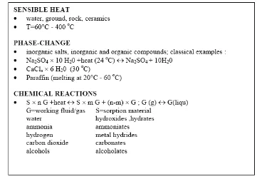
2.2 Physical Principal TES
When a thermal storage need occurs, there are three main physical principles to
provide a thermal energy function:
• Sensible heat
The storage is based on the temperature change in the material and the unit
storage capacity [J/g] is equal to heat capacitance × temperature change.
• Phase-change
If the material changes its phase at a certain temperature while heating the
substance then heat is stored in the phase change. Reversing, heat is dissipated
when at the phase change temperature it is cooled back. The storage capacity of
the phase change materials is equal to the phase change enthalpy at the phase
change temperature + sensible heat stored over the whole temperature range of
• Chemical reactions
The sorption or thermo chemical reactions provide thermal storage capacity. The
basic principle is: AB + heat A+B; using heat a compound AB is broken into
components A and B which can be stored separately; bringing A and B together
AB is formed and heat is released. The storage capacity is the heat of reaction or
free energy of the reaction.
The storage systems based on chemical reactions have negligible losses whereas
sensible heat storage dissipates the stored heat to the environment and need to be
[image:22.612.143.504.312.563.2]isolated.
Figure 2.1: Examples of material suitable for thermal storage
7
2.3 TES System
There are many technologies available for TES, but in this guide only ice storage
systems are considered. Chilled water storage is also very popular today; however,
because these systems generally don’t use glycol solutions, they are beyond the scope of
this guide.
The two most common types of ice storage are “ice on pipe” systems (also
known as "ice on coil" systems) and ice encapsulated in plastic containers. The ice on
pipe systems consist of coils of plastic or metal tubing immersed in a tank of water. A
chilled glycol and water solution is circulated through the tubes to build ice on the
outside of the tubes during the off-peak hours. When air conditioning is needed the same
solution is circulated through the tubes to melt the ice and provide chilled glycol
solution for building cooling. The second type of system works in the same fashion
except the glycol solution is circulated through a tank filled with plastic containers of
water. The ice forms in the containers and is later melted by the same glycol solution
when cooling is needed.
2.4 TES Design
The operating strategy depends on the objectives of the system design and,
ultimately, on capital and operating costs. The operating strategy may vary with time
due to seasonal weather variations or increased loads resulting from changes or additions
to the facility.
A storage medium for thermal energy either changes temperature-sensible energy
storage-or changes phases. Water or water-antifreeze solutions are the most common
storage. Eutectic salts are employed only in phase-change storage. Solids are used only
in sensible storage, usually in applications requiring small storage capacities.
In order to reduce tank size and cost, storage in liquids is usually accomplished
in stratified tanks rather than in separate tanks for warmer and cooler fluids.
Stratification means that warmer liquid floats on top of cooler liquid. This may be
achieved by using inlet and outlet diffusers as long as the temperature of the liquid in
storage does not traverse the neutral buoyancy point.
Phase-change storage for cooling can be implemented in a variety of ways, all of
which require circulating water or an antifreeze solution through the evaporator of a
refrigeration machine, or chiller. Storage systems include freezing ice on arrays of tubes
inside tanks, freezing ice or eutectic salts contained in capsules suspended in tanks, or
storing slurry comprised of very small ice particles suspended in a water-antifreeze
solution in a tank.
Stored thermal energy is lost over time due to the temperature difference
between the storage medium and its surroundings. The loss offsets energy savings and
should be taken into consideration. Insulation slows the rate of energy loss.
Mixing and heat transfer through the storage medium causes additional
thermodynamic losses, particularly for stratified sensible storage. However, recent
experience shows that both heated and cooled TES are capable of economically reducing