PC BASED OF MOTORIZED BALL VALVE POSITION
MOHD FADZLEE BIN AZMI
This Report is submitted in Partial Fulfillment of Requirements for The Degree of Bachelor in Electrical Engineering (Power Electronic and Drive)
Faculty of Electrical Engineering Universiti Teknikal Malaysia Melaka
“I hereby declared that I have read through this report and found that it has comply the partial fulfillment for awarding the degree of Bachelor of Electrical Engineering
(Power Electronic and Drive).”
Signature : ………
Supervisor’s Name : PN AIN AIN NUR BINTI HANAFI
“I hereby declared that this report entitle “ Pc Based of Motorized Ball Valve Position” is the result of my own research except as cited in the references. The report has not been accepted for any degree and is not concurrently submitted in candidature of any other degree.”
Signature : ………
Name : MOHD FADZLEE BIN AZMI
To my beloved mother and father, Mrs Salasiah Binti Ismail and Mr. Azmi Bin Yahya and family who provided me with love, guidance, enthusiasm, and support emotionally and financially throughout this long journey called my college career.
ACKNOWLEDGEMENT
In the name of Allah, The Most Gracious, The Most Merciful. Peace be upon the Messenger of Allah, Prophet Muhammad S.A.W, his companions (r.a) and followers until the end day.
First of all, I want to thanks my beloved mom and dad, whom keep prays for me, gives me freedom and show understanding to me as a student because their loves keep me moving forward.
Thanks to my supervisor for this final project, Mrs Ain Ain Nur binti Hanafi whom shares knowledge and idea so that I will keep on the right track which leads to this project. I also owe a great debt to Mohd Zaim bin Azmi as my Visual Basic instructor for his advices and contributions in this project.
Last but not least,to all my friends,thanks for all your supports.
ABSTRACT
This project is to design and develop a motorized valve position using computer interface. The purpose of control the valve is to control flow in the valve .The position of the valve is estimated using timer in visual basic programming and show in the interface using the scrollbar. The technique uses the capabilities of the computer's parallel port to provide an 8-bit input. The scope of this project is to control and upgrade a 2-way motorized ball valve into a multi position motorized ball valve. The software Microsoft Visual Basic is used as user interface.
ABSTRAK
TABLE OF CONTENTS
3 HARDWARE DEVELOPEMENT
3.1 Introduction 21
3.2 Valve 21
3.2.1 Valve flow characteristic 22
3.3 Motorized ball valve 24
3.3.1 Motorized ball valve opening and closing 25 3.3.2 Motorized ball valve user wiring 26 3.3.3 Motorized ball valve specifications 28
3.4 Relay board circuit 28
3.4.1 Relay board output circuit operation 29
3.5 Power supply 31
3.5.1 Components for power supply circuit 32 3.5.2 Components for interface circuit 32
3.6 Parallel port interface 33
4 SOFTWARE DEVELOPEMENT
4.1 Introduction 35
4.2 Program for user Interface 35
4.3 Program for valve control 38
4.3.1 The valve control graphical user interface 39 4.3.2 The valve control program flow chart 40 4.3.3 The valve control program operation 41
4.4 Hardware interface program 45
4.4.1 Declaring hardware Interface 45 5 RESULT AND DISCUSSION
5.2.2 Discussion for experiment 2 50
5.3 Experiment 3 51
5.3.1 Result of experiment 3 51
5.3.2 Discussion for experiment 3 52
LIST OF FIGURES
3.5 Motorized ball valve circuit wiring connection 273.6 Motorized ball valve wiring 27
3.7 Relay board 29
3.8 The relay board circuit 30
3.9 Power supply circuit simulation 31
3.10 Power supply ( 9-12vdc ) 31
3.11 Connection between parallel port, relay board 33 and motorized ball valve
5.2 Image captured by oscilloscope for the 47
LIST OF TABLES
TABLE TITLE PAGE
2.1 Motorized Valve AE-C Specifications 6 2.2 Hydraulic Valve AE-D Specifications 7
2.3 SPP signal definition 9
2.4 The resistor colour code 19
3.1 Motorized ball valve specification 28
3.2 Components for power supply circuit 32
3.3 Components for interface circuit 32
5.1 Result for experiment 1 47
5.2 Result for experiment 2 49
5.3 Result for experiment 3 (1) 51
5.4 Result for experiment 3 (2) 51
LIST OF APENDICES
APPENDIX TITLE
PAGE
A Motorized ball valve datasheet 60 B Relay circuit 76
CHAPTER 1
INTRODUCTION
1.1
Introduction
As technology progressed and the need for greater external connectivity increased, the parallel port became the means by which users could connect higher performance peripherals. In this project, parallel port is used as a medium of interfacing the software and the motorized valve. The reason of using parallel port in this project is because of its maximum data transfer rate which is around 150 kilobytes per seconds and it is extremely software intensive. But it has a distance limitation of only 6 feet for external cables[1].
This project is to control the position of 2-way motorized ball valve. It is also to upgrade the 2-way motorized ball valve into a multi position valve. The purpose of control the valve position is to control flow and pressure in the valve. The position of the valve is estimated using timer in visual basic programming and show in the graphical interface using a scrollbar.
This report discusses the design and development of the motorized valve positioner using computer interfacing. The discussion includes software and hardware development. The designing and developing procedure is simplified in the Project Development Flowchart shown in figure 1.1.
Figure 1.1: Project Development Flowchart. Project Review
Hardware design Software design
1.2
Project Overview
The purpose of this project is to design and develop a motorized valve positioner at a lower cost by using Visual Basic 6.0 as user interface and hardware interface. The progresses are divided into two parts. The first part is the valve and the second part is the controller of the valve.
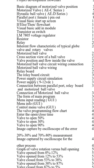
The valve used in this project is a motorized ball valve. PC is used as a controller for the valve. Software is used as user interface and hardware interface. The software used is Visual Basic 6.0. The basic diagram of the motorized valve positioner is shown in figure 1.2.
.
Figure 1.2: Basic Diagram of Motorized Valve Positioner Interfacing. Computer (Parallel Port) Relay Board Circuit
1.3
Project Objectives
The objectives of this project are as follows:
i) To upgrade a 2-way motorized ball valve into a multi position motorized ball valve.
ii) To estimate the position of the motorized ball valve using timer in Visual Basic 6.0.
iii) To develop a program using Visual Basic 6.0 that will drive the input of the parallel port
iv) To develop a low cost relay board circuit
1.4
Scope
The scope of this project is to control and upgrade a 2-way motorized ball valve into multi position motorized ball using Visual Basic.
1.5
Expected result
CHAPTER 2
LITERATURE REVIEW
2.1
Introduction
This chapter covers the study on the method used to develop this project. The method used to transmit the data is by using parallel port (parallel communication port) where it is interfaced by using Visual Basic 6.0.
2.2 Projects review
Figure 2.1: Motorized Valve (AE-C Series )
2.2.1 Motorized Valve (AE-C Series )
Description
It has spring return function and manual override Tab. Valve's actuator can be installed after valve body has been installed onto pipe. The valves are resistant to high moisture conditions, and feature a removable head. AE Series valves are available for low pressure steam applications.
2.2.2 Hydraulic ball valve (AE-D series)
Description
The AE-D series 2-position hydraulic valves are used in domestic and small commercial applications to control the flow of hot and/or cold water or glycol solution up to 50% concentration. These 2-Way valves are designed for ON-OFF control and can be piped for diverting or mixing valve applications for
Operating Voltage 220-240VAC50/60Hz
Rated Power 5W
Nominal Pressure 1.6Mpa Close-off Pressure 0.3Mpa
Applied Media Chilled water, hot water
domestic hot water service, in central heating and/or cooling systems; or for individual room temperature control (fan coil, radiator or convector applications).
Table2.2: Hydraulic ball valve (AE-D series) Specifications
2.3
Parallel Port
Parallel port is an inexpensive and yet powerful platform for implementing projects dealing with the control of real world peripherals. The parallel port provides eight TTL outputs, five inputs and four bidirectional leads and it provides a very simple means to use the PC interrupt structure [2]. Parallel port consists of three port addresses; data, status and control port. These addresses are in sequential order. That is, if the data port is at address 0x0378, the corresponding status port is at 0x0379 and the control port is at 0x037a.
2.3.1 Parallel Port Background
2.3.2 Parallel Port Overview
The parallel port, as implemented on the PC, consists of a connector with 17 signal lines and 8 ground lines. The signal lines are divided into three groups:
• Control (4 lines)
• Status (5 lines)
• Data (8 lines)
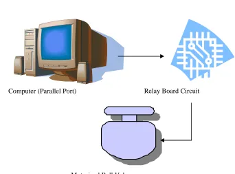
Data register is connected to Data lines, Control register is connected to control lines and Status register is connected to Status lines. The registers are virtually connected to the corresponding lines. So what ever the user write to these registers, will appear in corresponding lines as voltages, Of course, they can measure it with a multimeter. And if there is voltages connect to the parallel port can be read from these registers (with some restrictions)[1] . For example, if the user write '1' to Data register, the line Data0 will be driven to +5v. Therefore, it can be programmatically to turn on and off any of the data lines and Control lines. Figure 2.3 shows the parallel port pin assignments.
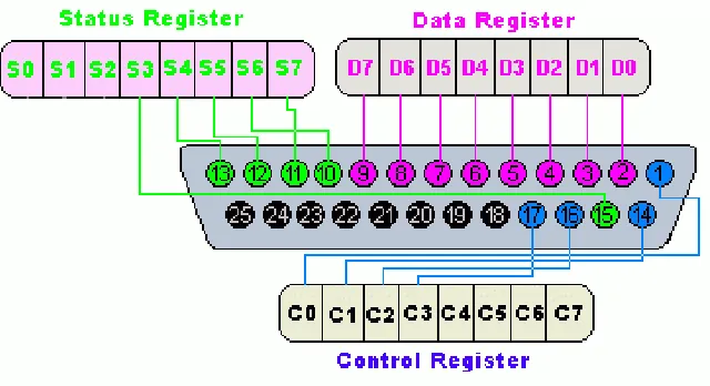
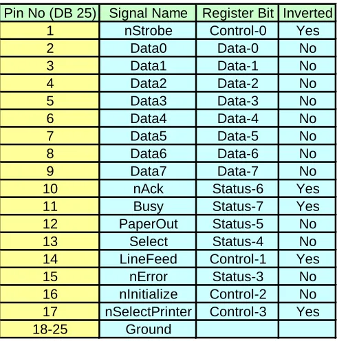
The details of parallel port signal lines are given in table 2.3 below:
Table 2.3: SPP Signal Definition.
Pin No (DB 25) Signal Name Register Bit Inverted
1 nStrobe Control-0 Yes
Table 2.3 identifies each of these signals and gives their Standard Parallel Port (SPP) definitions.
Pin 1 signal is an active low signal which indicates that the valid data is on the data lines.
Pin 2 until Pin 9 are the data lines.
Pin 10 is a low asserted pulse used to indicate that the last character was received.
Pin 11 is a high signal asserted by the printer to indicate that it is busy and cannot take data.
Pin 12 indicates that paper is empty.
Pin 13 asserted high to indicate that the printer is online.
Pin 15 is asserted low to indicate that some error condition exists.
Pin 16 is an active low signal. It is used to reset the printer.
Pin 17 is an active low signal which is used to indicate to the printer that it is selected.
Pin 18 until Pin 25 are grounded.
The signals within these groups are assigned to specific bits within the registers that make up the hardware/software interface to the parallel port. The parallel port is mapped into the I/O space of the PC. The registers consist as a contiguous block of 3 registers starting from the parallel port's base address. These ports are commonly referred to as the LPT ports and have the familiar I/O base addresses of 3BCh, 378h and 278h. Newer implementations of the parallel port, that support the advanced modes of IEEE 1284 standard, use 8 to 16 registers and are located at I/O addresses 378h or 278h, or are re-locatable, as in the case of a Plug and Play compliant parallel adapter[3,1].
2.3.3 Connection of The Parallel Port
2.4
Visual Basic 6.0
Visual Basic is one of the most exciting developments in programming for many years. Visual Basic is the next generation of BASIC and is designed to develop user-friendly programs.
Visual Basic Version 6.0 requires the Microsoft Windows operating system. Although we don’t need to be an expert user of Microsoft Windows, we do need to know the basics before we can master Visual Basic. We need to be comfortable with manipulating mouse, window and a few short key. However, there is no better way to master Microsoft Windows than to write applications for it and that is what Visual Basic is all about.
2.4.1 Theory on Visual Basic 6.0
Figure 2.4: Visual Basic Start Up Screen.
Visual Basic was designed to be usable by all novice or expert. The language is designed to make it easy to create simple applications, but can be used to develop fairly complex applications as well. Programming in VB is a combination of visually arranging components on a form, specifying attributes and actions of those components, and possibly writing additional lines of code for more functionality. Since default attributes and actions are defined for the components, a simple program can be created without the programmer having to write many lines of code. Performance problems were experienced by earlier versions, but with faster computers this has become less of an issue[6].