i
STATISTICAL ANALYSIS FOR FRONT END RF RECEIVER DESIGN
MOHD FIRDAUS BIN MUSTAFFA
This report is submitted in partial fulfillment of requirements for the award of
Bachelor of Electronic Engineering (Telecommunication Electronics)
With Honours
Faculty of electronic and Computer Engineering
University Technical Malaysia Melaka
UNIVERSTI TEKNIKAL MALAYSIA MELAKA
FAKULTI KEJURUTERAAN ELEKTRONIK DAN KEJURUTERAAN KOMPUTER
BORANG PENGESAHAN STATUS LAPORAN PROJEK SARJANA MUDA II
Tajuk Projek : STATISTICAL ANALYSIS FOR FRONT END RF RECEIVER DESIGN
Sesi
Pengajian : 2005/2009
Saya MOHD FIRDAUS BIN MUSTAFFA mengaku membenarkan Laporan Projek Sarjana Muda ini disimpan di Perpustakaan dengan syarat-syarat kegunaan seperti berikut:
1. Laporan adalah hakmilik Universiti Teknikal Malaysia Melaka.
2. Perpustakaan dibenarkan membuat salinan untuk tujuan pengajian sahaja.
3. Perpustakaan dibenarkan membuat salinan laporan ini sebagai bahan pertukaran antara institusi
pengajian tinggi.
4. Sila tandakan ( √ ) :
SULIT*
(Mengandungi maklumat yang berdarjah keselamatan atau kepentingan Malaysia seperti yang termaktub di dalam AKTA RAHSIA RASMI 1972)
TERHAD* (Mengandungi maklumat terhad yang telah ditentukan oleh
organisasi/badan di mana penyelidikan dijalankan)
TIDAK TERHAD
Disahkan oleh:
__________________________ ___________________________________
(TANDATANGAN PENULIS) (COP DAN TANDATANGAN PENYELIA)
Alamat Tetap:50 PERSIARAN TAWAS BARU 22, KG TERSUSUN TAWAS TAMBAHAN, KG TAWAS 30010 IPOH
ii
I hereby declare that this report is the result of my work except for quotes as cited in
the references.”
Signature
: ………
iii
“I hereby declare that I have read this report and my opinion this report is sufficient in
terms of the scope and quality for the award of Bachelor of Electronic Engineering
(Telecommunication Electronics) With Honours”.
Signature
: ……….
iv
v
ACKNOWLEDGEMENT
Alhamdulillah
Praise to Allah S.WT The Most Gracious, The Most Merciful, there is no power no
strength save in Allah, The Highest and The Greatest, whose blessing and guidance have
helped me through the process of completing this project. Peace and blessing of Allah be
upon our prophet Muhammad S.A.W who has given light to mankind.
My deepest gratitude goes to my supervisor Abdul Rani b Othman at for all the
knowledge, motivation and support that he had given me in completing this report. Lots
of love from deepest of my heart goes to my family especially my parents whom always
given me their love and warm support.
I sincerely and almost thank all of my teachers, lecturers and all of my friends for
helping directly or indirectly for this project.
vi
ABSTRACT
vii
ABSTRAK
viii
TABLE OF CONTENTS
CHAPTER TITLE
PAGES
PROJECT TITLE
i
STATUS REPORT FORM
ii
STUDENT DECLARATION
iii
SUPERVISOR DECLARATION
iv
DEDICATION
v
ACKNOWLEDGEMENT
vi
ABSTRACT
vii
CONTENT
ix
LIST OF TABLE
xiii
LIST OF FIGURE
xiv
1
INTRODUCTION
1
1.1
Project Background
1
1.2
Problem Statement
3
1.3
Objectives
3
1.4
Scopes
3
1.5
Methodology
4
ix
1.7
Conclusion
4
1.8
Report Structure
5
2.
LITERATURE REVIEW
6
2.1
Literature Review
6
2.2
Introduction to Wireless LAN (WLAN)
7
2.3
Advantages of WLAN
8
2.4
RF Front End Receiver
9
2.5
Review of Front End RF Receiver
10
2.6
Low Noise Amplifier/ Power Amplifier
13
2.7
Cascaded Receiver System
14
2.8
Receiver Nonlinear Performance
18
2.8.1 Gain Compression
18
2.8.2 Intermodulation Distortion
21
2.8.3 Dynamic Range
29
3
REASEARCH METHODOLOGY
32
3.1
Understanding the project
33
3.2
RF Front End Receiver design overview
33
3.3
Component Selection
34
3.4
Design Calculation
34
x
3.4.2 Noise Figure Calculation
35
3.4.3 IIP3 (Third Order Intercept Point) Calculation
36
3.4.4 Gain Compression
37
3.4.5 Dynamic Range
37
3.5
Design Simulation
38
3.5.1 Gain, Noise Figure, and Power Simulation
38
3.5.2 P1dB Gain Compression Simulation
39
3.5.3 Intermodulation Distortion (IMD) Simulation
42
3.6
Result Discussion
43
4
PROJECT’S RESULT AND DISCUSSION
45
4.1
Component Selection
46
4.2
Design Calculation
47
4.3
Design Simulation
47
4.3.1 Gain Simulation Result
47
4.3.2 Power Simulation Result
49
4.3.3 Noise Figure Simulation Result
50
4.3.4 P1dB Gain Compression Simulation
51
4.3.5 Intermodulation Distortion Simulation
54
xi
5
CONCLUSION
56
5.1
Conclusion
56
5.2
Future Work
57
xii
LIST OF TABLES
NO
TITLE
PAGE
2.1
Comparison between WLAN and Bluetooth
7
2.2
Summary of receiver review
13
3.1
DCR RF Parameters to meet the 802.11a WLAN standard
requirement
36
4.1
Calculation Result
47
4.2
Gain Simulation Result
48
4.3
Power Simulation Result
49
4.4
Noise Figure Simulation Result
51
xiii
LIST OF FIGURES
NO
TITLE
PAGE
1.1
Example DCR block Diagram
2
2.1
Block Diagram of WLAN System
8
2.2
Block Diagram of Front End Receiver
10
2.3
Cascaded Receiver System (Cascaded Noise Temperature)
15
2.4
Cascaded Receiver System (Cascaded Noise Figure)
16
2.5
Ideal Two-Port Pout Versus Pin Characteristic
19
2.6
Two-Port Gain Versus Input Power Level
20
2.7
Receiver Circuits and Intermodulation Distortion
22
2.8
Output Power Pout for One Fundamental Frequency Signal
Versus Input Power Pin
24
2.9
Fundamental Po and Third-Order Distortion Pd Output Powers
Versus Input Power Pin
24
2.10
Typical Output Spectrum of a Two-Port Receiver Network
27
2.11
Cascaded Receiver Networks
28
2.12
Dynamic Range
30
3.1
Block Diagram of front end Receiver
33
3.2
Receiver simulation diagram
38
xiv
3.4
Noise Figure Simulator
39
3.5
Power Simulator
39
3.6
Gain Compression Diagram
40
3.7
Gain Compression Simulator
41
3.8
Intermodulation Distortion Diagram
42
3.9
Intermodulation Simulator
42
3.10
Project Flow
44
4.1
Gain Simulation Graph
49
4.2
Power Simulation Graph
50
4.3
Noise Figure Simulation Graph
51
4.4
Gain Compression Graph
52
4.5
Output spectrum at 1 dB Gain Compression Point
53
4.6
Gain versus Output Power
53
1
CHAPTER 1
INTRODUCTION
1.1 Project Background
Telecommunication is the extension of communication over a distance. The
elements of a telecommunication system are a transmitter, a medium and possibly a
channel imposed upon the medium and a receiver. The transmitter is a device that
transforms or encodes the message into a physical phenomenon, the signal. The
receiver has a decoding mechanism capable of recovering the message within certain
limits of signal degradation. In telecommunication, antenna is the best example to
describe this system. Antenna is designed to transmit or receive a signal/radio wave.
In this report, it discussed more about receiver. RF front end is a generic term for
everything in a receiver that sits between the antenna and the intermediate frequency
(IF) stage. Usually, the receiver circuit is combining with the transmitter circuit
where it called transceiver. There are many type of front end receiver in the
2
reflectional receiver, homodyne detection, low IF receiver, tuned radio frequency
receiver, and superheterodyne receiver. To design a good front end receiver circuit,
some of specifications must be taken. The front end receiver must be good image
rejection, lower complexity and fewer components. Because of that a suitable
architecture of the receiver must be consider to design this front end receiver
circuit.[1].
The direct conversion principle has been well known as a demodulation
method, especially for an AM signal, under the name of ‘‘synchrodyne” or
“homodyne”[2]. An example of such efficient receiver architecture is a direct
conversion receiver as presented in [3]. The main feature of direct conversion
receivers is the down-conversion of the radio signal to baseband without any use of
intermediate frequencies.
The 802.11a wireless local-area-network (WLAN) system, which uses
orthogonal frequency division multiplexing (OFDM) [4], offers different
communication data rates (through 6 to 54 Mbps) in the 5-GHz band. The principle
of OFDM is to split high-rate data streams into a number of lower rate streams that
are transmitted simultaneously over a number of subcarriers. To implement an
802.11a WLAN receiver, a direct conversion receiver (DCR) is more suitable than a
heterodyne receiver. A typical Direct Conversion Receiver (DCR) block diagram is
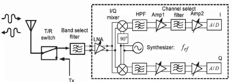
[image:18.612.134.516.519.654.2]shown in Figure 1.1.
3
In this paper, a direct conversion receiver for 5.8 GHz (WLAN) system is
presented, which is good image rejection, lower complexity, less component count
and low noise figure.
1.2 Problem Statements
The major problems in this project are to choose suitable architecture for the
receiver, optimize and design the suitable receiver for the specified requirement. The
inefficient simulation technique in design tools is another challenge in getting
accurate simulation result.
1.3Objectives
The main objective in this project is to develop and optimize Front-End direct
conversion receiver at 5.8 GHz.
1.4 Scopes
The scope of the research work comprises as follows:
a) RF components such as low noise amplifier, RF amplifier, power divider and
filter is selected to fulfill RF receiver architecture.
b) RF budgets such as gain, noise figure and IP3 are calculated and analyzed
according to designed RF components.
c) The selected direct conversion receiver is then modeled in the ADS2005A
software based on designed components. The DCR model is simulated for
4
1.5 Methodology
The method includes:
a) RF components for the receiver are chosen. RF budgets for the RF receiver
design are calculated according to the parameters of the selected components
in data sheet.
b) The RF receiver is modeled by using ADS2005A software. The RF receiver
models are then simulated for system characteristic such as gain compression
and third input intercept point (IIP3). This followed by system performance
analyses according to IEEE802.11a standard[4] where the effects of RF
distortions on the system performance are analyzed.
1.6 Expected Outputs
At the end of this project, the front-end direct conversion receiver is expected
to be successfully developed for WLAN application. As the final result, front-end
receiver will obtain the good sensitivity, gain, maximum receiver strength, low noise
figure, IIP3, P-1dB and Dynamic Range.
1.7 Conclusion
In this project, a direct conversion RF front-end receiver for 5.8 GHz
(WLAN) system will be presented, which is good image rejection, low power
consumption, lower complexity, less component count and low noise figure and
5
1.8 Report Structure
This report was divided into five chapters. The first chapter is focusing on the
introductions of the project. The introduction consist of the project brief introduction,
objective of the project, the project statement, scope of work, project methodology
and the report structure.
The second chapter is about the literature review. This chapter is focusing on
the documentation of the theory that related in designing receiver. The reviews of
previous case study are also included in this chapter,
The third chapter is mainly about the research methodology. All the progress
and work flow are describe in this chapter.
The fourth chapter is about the project progress focusing on the result of the
simulation. All the data that were obtain during this semester will be documented in
this chapter. The full project results are shown.
The final chapter is focusing on the discussion and conclusion of this report.
These include the entire result and its justification. Some suggestion on improving
6
CHAPTER 2
LITERATURE REVIEW
2.1 Literature Review
This chapter develops some basic principles used in the analysis and design
of Front End Receiver. The most important design considerations in front End
Receiver are Gain, Noise Figure, Sensitivity, and IMD (Intermodulation Distortion ).
To ensure the designed circuit fulfills performance requirement and could be install
as a practical component in the future, one of the popular standard followed by the
market product, which is developed by Institute of Electrical and Electronic
Engineering (IEEE), is taken as the major requirement that design circuit should
7
2.2 INTRODUCTION TO WIRELESS LAN ( WLAN)
Wireless technology has been available for a long time and it is only until
recent few years that wireless LAN (WLAN) becomes popular. WLAN has
continued to grow at incredible rate. Due to the convenience, availability, and cost of
wireless hardware, there is an explosive growth in WLAN deployment and
manufacture of WLAN hardware. It is therefore necessary to have organizations such
as FCC, IEEE, the Wi-Fi Alliance and WLANA to remove barrier of operations
between solutions.[5]
A wireless LAN is a data transmission system designed to provide
location-independent network access between computing devices by using radio waves rather
than a cable infrastructure. In the corporate enterprise, wireless LANs are usually
implemented as the final link between the existing wired network and a group of
client computers, giving these users wireless access to the full resources and services
of the corporate network across a building or campus setting. The widespread
acceptance of WLANs depends on industry standardization to ensure product
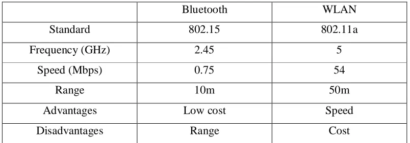
compatibility and reliability among the various manufacturers. Table 2.1 shows the
[image:23.612.125.527.568.709.2]comparison between WLAN and Bluetooth.[5]
Table 2.1 : Comparison between WLAN and Bluetooth
Bluetooth WLAN
Standard 802.15 802.11a
Frequency (GHz) 2.45 5
Speed (Mbps) 0.75 54
Range 10m 50m
Advantages Low cost Speed
8
Figure 2.1: Block Diagram WLAN system
2.3 ADVANTAGES OF WLAN
What are the concrete benefits of WLAN over wired networks? While the
most obvious is mobility, there are advantages also in building and maintaining a
wireless network. Let us look at the benefits more closely:
a) Mobility - Mobility is a significant advantage of WLANs. User can access
shared resources without looking for a place to plug in, anywhere in the
organization. A wireless network allows users to be truly mobile as long as
the mobile terminal is under the network coverage area.
b) Range of Coverage - The distance over which RF and IR waves can
communicate depends on product design (including transmitted power and
receiver design) and the propagation path, especially in indoor environments.
Interactions with typical building objects, such as walls, metal, and even