A SMART – AGRI ROBOT IN AGRICULTURE SECTOR
TEE KOK LIANG
This report is submitted partial fulfillment of the requirement for the award of Bachelor of Computer Engineering With Honours
Faculty of Electronic and Computer Engineering Universiti Teknikal Malaysia Melaka (UTeM)
UNIVERSTI TEKNIKAL MALAYSIA MELAKA
FAKULTI KEJURUTERAAN ELEKTRONIK DAN KEJURUTERAAN KOMPUTER
BORANG PENGESAHAN STATUS LAPORAN PROJEK SARJANA MUDA II
Tajuk Projek: A SMART – AGRI ROBOT IN AGRICULTURE SECTOR Sesi Pengajian: 2010/ 2011
Saya TEE KOK LIANG
(HURUF BESAR)
mengaku membenarkan Laporan Projek Sarjana Muda ini disimpan di Perpustakaan dengan syarat- syarat kegunaan seperti berikut:
1. Laporan adalah hakmilik Universiti Teknikal Malaysia Melaka.
2. Perpustakaan dibenarkan membuat salinan untuk tujuan pengajian sahaja.
3. Perpustakaan dibenarkan membuat salinan laporan ini sebagai bahan pertukaran antara institusi pengajian tinggi.
4. Sila tandakan ( √ ) :
(Mengandungi maklumat yang berdarjah keselamatan atau
SULIT*
TERHAD*
TIDAK TERHAD
________________________________
(TANDATANGAN PENULIS)
Alamat Tetap: TN 95-5, JLN 10 TMN SRI
NANING SPG 4, 78000 ALOR GAJAH
MELAKA.
Tarikh: 2 MAY 2011
kepentingan Malaysia seperti yang termaktub di dalam AKTA RAHSIA RASMI 1972)
(Mengandungi maklumat terhad yang telah ditentukan oleh organisasi/badan di mana penyelidikan dijalankan)
Disahkan oleh:
___________________________________
(COP DAN TANDATANGAN PENYELIA)
iii
“I hereby declare that this report is the result of my own except for quotes as cited in
the references”
Signature : ………
Author : TEE KOK LIANG
iv
“I hereby declare that i have read this report and in my opinion this report is
sufficient in terms of the scope and quality for the award of Bachelor of Electronic
Engineering (Computer Engineering) with Honours”.
Signature : ………..
Supervisor Name : ENGR. MUZAFAR BIN ISMAIL
v
ACKNOWLEDGEMENT
This project cannot be developed without the support of many people. My
first acknowledgement goes to my project supervisor, ENGR. Muzafar Bin Ismail
who taught and guides me for this project. He also got teach me the way to produce a
good thesis and presentation slides during this period. I would also like to
acknowledge the support and ideas of my friends Victor Voon Chun Howe, Lee Wen
Yuh, Chang Boon Hai and Wong Kok Hong.
Beside that, I would also like to acknowledge to my parents who are giving
me moral and finance support for completed the project. To the technicians of PSM
lab of UTeM, I am also very appreciated to their co-operation during I am used the
lab equipments.
Because so much goes into a project like this, we probably forgot to thank
some very deserving people and for that we apologize. Please know in your hearts
that we are grateful and very aware that a project like this is the result of lots of hard
work and, without a doubt, the blessing of God.
vi
ABSTRACT
This project provides the opportunity for the researcher to have a deeper
understanding on the robot that used in agriculture industry. The project will come
out a small prototype car with a tank that can store a liquid like fertilizer or
pesticides. This project also will focus on the software and hardware design.
On the first chapter of the thesis, I will introduce about the smart- agri robot
in agriculture industry. In this chapter, it have consist of several sub- title which have
include the problem statement, objective, scope of work, motivation of the work and
will ending with project methodology. For the chapter 2, it is consist of literature
review. For this chapter, it will covered on the control circuit and theoretical that I
will use in this project. Besides that, it also have include some theoretical of the main
components such as PIC microcontroller 16F877A, IR sensor and some technical
knowledge which will covered into this chapter.
All of this technical knowledge such as the important of protective diodes and
interfacing relay to microcontroller for protecting the circuit. The next chapter which
is chapter 3, it is covered about the methodology for designing the project. For the
following chapter of this project will be chapter 4. In this chapter, I will explain more
on the operation and processes that will undertake in this project. The final chapter
vii
ABSTRAK
Projek ini adalah memberi kesempatan bagi penyelidik untuk mendalami
pemahaman yang lebih luas atas robot yang boleh digunakan dalam sektor pertanian.
Projek ini juga akan dicipta dengan kereta prototaip ya kecil serta tangki yang boleh
menyimpan air ataupun cecair seperti baja dan racun serangga. Projek ini akan
menfokuskan pada perisian software dan juga hardware. Ia terbahagi kepada lima
bab secara keseluruhannye dan diakhiri dengan cadangan untuk projek dan
kesimpulan. Pada bab 1, ia akan memperkenalkan tentang fungsi robot pintar di
sektor pertanian. Dalam bab ini, ia terdiri daripada beberapa sub-tajuk yang meliputi
laporan masalah, tujuan, ruanglingkup kerja, motivasi kerja dan akan berakhir
dengan metodologi projek.Untuk bahagian bab 2, ia terdiri daripada kajian literatur.
Dan ia akan diterangkan dalam bahagian litar kawalan dan teori yang akan saya
gunakan dalam projek ini. Selain itu, ia juga telah merangkumi beberapa teori pada
komponen utama seperti mikrokontroler PIC 16F877A, sensor IR dan beberapa
pengetahuan teknikal yang akan diterangkan dalam bab ini. Pengetahuan teknikal
seperti penting dari dioda pelindung dan relay interfacing ke mikrokontroler bagi
melindungi litar-litar projek.Pada bahagian seterusnya akan disambung dengan bab
3, ditutupi tentang metodologiuntuk mendesain projek. Bagi bab berikutnya, iaitu
bab 4, ia akan menerangkan dengan lebih jelas mengenai operasi dan proses yang
akan mengambil tindakan dalam projek ini. Untuk bab terakhir untuk laporan ini,
saya akan memberi cadangan projek untuk penambahbaikkan pada projeck tersebut
viii
LIST OF FIGURES
NO TITLE PAGE
2.1 The relay circuit symbol and mechanical structure of relay 7
2.2 The circuit of protection diodes for relays 7
2.3 The voltage regulator physical stucture 8
2.4 The physical appearance of the voltage regulator 8
2.5 A microcontroller based system 9
2.6 (a) The physical appearance of the PIC 16F877A, 10
(b) USB ICSP PIC programmer. 10
2.7 The standard pin configuration for PIC16F877A 40- pin header box 11
2.8 PIC16F877A bubles diagram 14
2.9 (a) A Pierce oscillator configuration that suitable for use with crystals
and ceramic resonators 15
(b) A simple discrete RC oscillator 15
2.10 The schematic diagram illustrate the clock oscillator 16
2.11 The physical view of 8Mhz crystal oscillator 17
2.12 The block diagram of the speed controller 18
ix
2.14 The physical appearance of the LM324 19
2.15 The transmitted signal between two IR sensor 20
2.16 Two packages IR sensor (3mm or 5mm) 21
2.17 The physical and mechanical view of the ULN 2803 21
2.18 The connection of relay and microcontroller by using ULN 2803 22
2.19 The physical view and pin configureation of H-bridge motor driver 23 3.1 The main page of the PIC C compiler 25 3.2 The PICKit2 – User Interface 26
3.3 The main page of Proteus 7 (ISIS) 27 3.4 The main page of Proteus 7 (ARES) 27
3.5 The examples of 3D visualization in “ARES” 28 3.6 The Gantt chart for PSM 1 29 3.7 The Gantt chart for PSM 2 29 3.8 The flow chart of the project implementation 31
3.9 The flow chart of operation Smart- Agri robot 32 3.10 The sequence of work by the Smart- Agri robot 33 3.11 The flowchart of circuit troubleshooting 34 4.1 The schematic diagram of microcontroller PIC16F877A 37
4.2 The reflection of the emitter and detector IR 45
4.3 The top view of pin configuration of Op- Amp (LM324) 46
4.4 The condition when IR is not incident upon the Rx 47
4.5 The condition when IR is in incident upon the Rx 47
x
4.7 The full H-Bridge circuit in reverse condition 49
4.8 The full H-Bridge circuit in forward condition 49
4.9 The PWM signals of varying duty cycles 51
4.10 The schematic of the PIC microcontroller 52
4.11 The 3D visualization of the PIC microcontroller 53
4.12 The schematic of the Voltage regulator 53
4.13 The 3D visualization of the voltage regulator 54
4.14 The schematic of the motor driver (L298N) circuit 54
4.15 The 3D visualization of the PIC microcontroller 55
4.16 The schematic of the IR sensor circuit 55
4.17 The top view of the IR sensor circuit 56
4.18 The front view of the Smart- Agri Robot 56
4.19 The top view of the Smart- Agri Robot 57
4.20 The side view of the Smart- Agri Robot 57
5.1 The GP2D12 infrared distance sensor 59
5.2 The remote control transmitter 60
xi
LIST OF TABLES
NO TITLE PAGE
2.1 The PIC16F877A pins description 11
2.2 The function of modules in PIC16F877A 13
2.3 The values of capacitor range that used in variant types of oscillator 16
xii
LIST OF AMBREVIATIVES
A/D - Analog To Digital
DC - Direct Current
EEPROM - Electrically Erasable Programmable Read-Only Memory
Emf - Electromotive Force
GND - Ground
I/O - Input/Output
I2C - Inter-Integrated Circuit
IC - Integrated Circuit
ICSP - In Circuit Serial Programming
IR - Infrared Radiation
LCD - Liquid crystal display
LED - Light Emitting Diode
LIN - Local Interconnect Network
NC - Normally Close
xiii
PCB - Printed Circuit Board
PIC - Programmable Integrated Circuit
PSP - Parallel Slave Port
PWM - Pulse Width Modulation
SPI - Serial Peripheral Interface
SSP - Synchronous Serial Port
TTL - Transistor- transistor Logic
xiv
LIST OF APPENDIXS
NO TITLE PAGE
1 Datasheet PIC16F87XA 64
2 Datasheet L298 66
xv
TABLE OF CONTENTS
CHAPTER TITLE PAGE
ACKNOWLEDGEMENT v
ABSTRACT vi
ABSTRAK vii
LIST OF FIGURE viii
LIST OF TABLE xi
LIST OF AMBREVIATIVES xii
LIST OF APPENDIXS xiv
TABLE OF CONTENTS xv
I INTRODUCTION 1
1.1 Problem Statement 2
1.2 Objective 2
1.3 Scope of works 3
1.4 Motivation of the works 3
1.5 Project methodology 3
1.5.1 Project planning 4
1.5.2 Literature review 4
xvi
II LITERATURE REVIEW 5
2.1 Introduction 5
2.2 Control circuit 6
2.3 Components And Equipment 2.3.1 Relay 6
2.3.1.1 Protection diodes for relays 7
2.3.2 Voltage Regulator 8
2.3.3 Microprocessor 16F877A 9
2.3.4 The advantages of PIC16F877A 10
2.3.5 Crsystal clock oscillator 15
2.3.5.1 Speed controllers by using the Pulse Width Modulation 17
2.3.6 Op- Amp (LM324) 18
2.3.7 IR LED emits infrared radiation 19
2.3.8 ULN 2803 21
2.3.9 Interfacing relay to microcontroller 22
2.3.9.1 Back emf 22
2.3.10 H- Bridge Motor Driver (L298N) 23
III PROJECT METHODOLOGY 24
3.1 Introduction 24
3.2 Collection Data 24
3.3 Project Planning 28
xvii
3.5 The flow chart of the operation Smart- Agri robot 32
3.6 Circuit Troubleshooting 33
IV RESULTS AND DISCUSSION 35
4.1 Introduction 35
4.2 Operational of PIC16F877A microcontroller 36
4.2.1 Operation of the circuit 36
4.2.1.1 Programming (coding) of the project 38
4.3 The operation of IR sensor 44
4.3.1 Operation of the IR sensor 44
4.4 IR sensor controlller (Op-Amp LM324) 45
4.5 Operation of Dual H- Bridge motor driver (L298N) 48
4.6 Operation of Pulse Width Modulation (PWM) 50
4.6.1 Setting up PWM in PIC16F877A 51
4.7 Schematic & 3D visualization of the hardware 52
4.8 Prototype picture of the Smart-Agri Robot 56
V CONCLUSION AND RECOMMENDATION 58
5.1 Project recommendation 59
5.1.1 Recommendation for the IR sensor 59
5.1.2 Recommendation for interface between robot and the software 59
5.2 Conclusion 61
REFERENCES 62
1
CHAPTER I
Introduction
The inspiration of this project came from the fully functional insects that needed to be eliminating in agriculture sector. Nowadays, robotics is one of the fastest growing in engineering fields. The robots are design to remove the human factor from labor intensive or dangerous work. The microcontroller is the brain of the robot that will receives data from various sources to control the movement of the robot in order to accomplish a task. This Smart-Agri robot is used in agricultural industry. Therefore, for applying this concept, I will design a prototype vehicle that can replace humans in the process of poison plants on a large scale.
2
1.1 Problem statement
The agriculture culture is an important field in Malaysia, it was essence of development movement in Malaysia, without agriculture industry perhaps Malaysia are going to face famine crisis. If we still reliance Malaysia on external agriculture industry, we will in trouble to produce more output in this sector. This is also to avoid the basic supply of necessities lack in the market. However, the frequent on industrial development will face some problem like the shortage of labor, highest labor salary, weather imbalance, and technology usage restriction in agriculture sector. As such modern technology, it usage are necessary to extend more agricultural products in a wide range. It also can realize the desire of the government to be success in agriculture’s sector. Therefore, the application of sophisticated technology must be use to maximize the agricultural products in this country. It also can realize the government's desire to develop modern sector agriculture in this country.
1.2 Objective
The objectives of this Smart- Agri robot is to reduce the burden of farmers or consumer in agriculture sector. Besides that, this project will create the talent of student to apply their knowledge in this final year project. The objectives and goals of this project are:
i. To improve the efficiency of the logistics system, this is because all fertilization process will spray out with schedule and the Agri-robot could determine the rate of the fertilization that needed by the plant.
ii. Due to all the workplaces are implicated with phytocide and insect, it also can mitigate the accident’s rate at the workplaces.
3 iv. To reduce the mistake in process of poisoning and fertilization, because
theis Smart- Agri robot did not have the emotional like human.
1.3 Scope of works
This project will focus on hardware and software for this smart robot. In this project, I will design it with a tank which can store a liquid like fertilizer or pesticides the plant. It have been designed with the combination of the five main controller circuit. These five main components that I am using in this project which are includes:
• the programmable integrated circuit (PIC16F877A) which function as main brain of the project,
• H-Bridge motor driver (L298N) is used as the motion control of the smart robot is control,
• Infrared Radiation sensor circuit used to detect the track of the Smart- Agri robot and position of the plants.
• Relay controller circuit which is used to control the voltage of the water dispenser
• Finally, by using this smart robot, all the process of fertilizing and pesticides will work effectively.
1.4 Motivation of the works
To reduce the burden of farmer and settle up the problem of farmer in agriculture sector.
4
1.5 Project methodology
In this part, I have cover three main things to finish my project which are project planning, literature review and finishing part of the project. The below will be the main topic and sub topics that will be further elaborated in the report.
1.5.1 Project planning
• Understanding the concept and theory of the project
• Prepare Gantt Chart for guidelines and progress of the project
1.5.2 Literature review
• Search some suitable and practical circuits
• List down and identify the suitable components that using in the project.
• Design a prototype circuit boards and assembling
• Test and do analysis to the circuits
1.5.3 Finishing
• Testing of final assembly circuit in operation, application record the results
• Presentation of the project
5
CHAPTER II
LITERATURE REVIEW
2.1 Introduction
The idea to create "Agri-Mobile" is the result of our study on the problems faced by farmers today, which is about the poison work that are not done properly. Therefore, I have do some research on several books of the electronic circuit books, websites, e-books and journals from the internet. After that, I start to plan the work on how to integrate the circuits in this project.
6
2.2 Control circuit
Control circuit is the most important part in this project, this is to make sure that the project can be function well as the planned. In this project, I have chosen some control circuit such as, Microcontroller, speed controller and motor driver circuit. All of this control circuit are use to make sure that the circuit can operate and perform well in future.
2.3 Components and equipment
Electronic components are the most important appliance in an electronic circuit. Components or circuit findings are create and defined by performance characteristics of a component. Components are produced with its own functions and operated in accordance with the resolution made. The components that will use in this project are the microprocessor, resistor, capacitor, relay etc. There are also a variety of tools used such as soldering iron, suckers, and others.
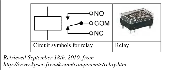
2.3.1 Relay
A relay is functioning as an electrically operated switch. The current flowing through the coil of the relay will create a magnetic field, which attracts a lever and changes the switch contacts. The relay’s switch connections are usually label as NC (normally close), NO (normally open) and COM (Common). The current will flows through a switch and an electromagnetic coil to the ground.
7 in de- energized position. When the control circuit switch is closed, the current flows to the relay and energized the coil.
Retrieved September 18th, 2010, from
[image:24.595.130.506.155.294.2]http://www.kpsec.freeuk.com/components/relay.htm Circuit symbols for relay Relay
Figure 2.1: The relay circuit symbol and mechanical structure of relay.