i
“I hereby declare that I have read through this report entitle “Leap Motion – Controlled robotic arm” and found that it has comply the partial fulfillment for awarding the degree of Bachelor of Electrical Engineering (Mechatronic Engineering)”
Signature : ...
Supervisor’s Name : ...
LOI WEI SEN
...ii
LEAP MOTION – CONTROLLED ROBOTIC ARM
LEE JUN WEI
A report submitted in partial fulfillment of the requirements for the Degree of
Mechatronic Engineering
Faculty of Electrical Engineering
UNIVERSITI TEKNIKAL MALAYSIA MELAKA
iii
I declare that this report entitle “Leap Motion –Controlled robotic arm” is the result of my own research except as cited in the references. The report has not been accepted for any degree and is not concurrently submitted in candidature of any other degree.
Signature : ...
Name : ...
LEE JUN WEI
...iv
To my beloved Mother and Father
Thank you for your incessant support and encouragement. Your sacrifices and loves have helped me to achieve this accomplishment.
Dear Lecturers and Supervisors
Thank you for your continuous support, knowledge and guidance.
Dear Friends
v
ACKNOWLEDGEMENT
First and foremost, I would like to take this chance to thank my beloved supervisor Mr. Loi Wei Sen for giving the support mentally and physically, by sharing his expertise, knowledge and experience with me. He has always provides me with guidance on how my project should work and gives me new idea to be implemented, as well as solutions for some difficult problems. Never forget the good advices I got from Mr. Lim Wee Teck, Ms. Nur Maisarah binti Mohd Sobran and Ms. Arfah binti Ahmad to do a better report. Nevertheless, as my first panel, Dr. Ahmad Zaki has guided me about my hardware as Dr. Zaki is major in robotics field.
I am highly indebted to pioneers, Tham Yu Jiang and Ali Mutasim who have provided me with the valuable guidance and knowledge which very friendly to share although distance is not allow to meet, and I appreciated it with all of my heart.
vi
ABSTRACT
vii
ABSTRAK
ix
3.2.3 Make Connection between the Leap Motion Controller and the Robotic Arm 12 Arm and Test the reliability of the Robotic Arm 18 3.4 Experiment 19
3.4.1 Experiment 1: Error of the Servomotor 19 3.4.2 Experiment 2: Accuracy’s Reliability on the Waist Experiment 22 3.4.3 Experiment 3: Precision of the Robotic Arm by Repeatability Test 24
3.4.4 Validity of the Experiment 26
3.4.5 Reliability of the Experiment 26 3.5 Cost and Budget 27
3.6 Gantt Chart 28
4 RESULT AND DISCUSSION 29
4.1 SolidWorks Drawing 29
x
4.4.1 Restrict Certain Inputs to Prevent Physical Damage 33
4.4.2 Mathematical Functions 34
4.4.3 Inverse Kinematics Equations 34
4.4.4 Finger Distance (of Two Fingers only) Controls the End Effector 35
4.7.1 Experiment 1: Error of the Servomotor 45 4.7.1.1 Error of the Servomotor after Calibrated Value Added 45 4.7.2 Experiment 2: Accuracy’s Reliability on the Waist Experiment 49 4.7.3 Experiment 3: Precision of Robotic Arm by Repeatability Test 54
4.8 Completion of the Robotic Arm 56 4.8.1 User Interfaces 57
xi
CHAPTER TITLE PAGE
5 CONCLUSIONS AND RECOMMENDATIONS 59
5.1 Conclusion 59
5.2 Recommendations and Suggestions 60
REFERENCES 61
xii
LIST OF TABLES
TABLE TITLE PAGE
3.1 Cost and budget of material 28 4.1 Average servomotor angles compared to programmed angles 43 4.2 Percentage of relative error of the servomotor from 0 ̊ to 180 ̊ 44 4.3 Average servomotor angles compared to programmed angles 46 4.4 Percentage of relative error of the servomotor from 0 ̊ to 180 ̊ 47 4.5 Waist of the robotic arm’s servomotor angles before introduced the
calibrated value 50
4.6 Waist of the robotic arm’s servomotor angles after introduced the
calibrated value 52
xiii
3.11 The Cartesian coordinate of the Leap Motion controller 21
xiv
4.9 Gripper open small 37
4.10 Hand move right 37
4.11 Hand move left 38
4.12 Wrist supination 90 ̊ 39
4.13 Wrist pronation 90 ̊ 39
4.14 Wrist extension 90 ̊ 39
4.15 Wrist flexion 90 ̊ 40
4.16 Shoulder and elbow at initial position 41
4.17 Wire connection on Arduino Uno 41
4.18 Servomotor error angles from 0 ̊ to 180 ̊ 48 4.19 Servomotor at 90 ̊ before include calibrated value 48 4.20 Servomotor at 90 ̊ after included calibrated value 49 4.21 Servomotor error angles from -200mm to 200mm 53
4.22 Position of the samples 55 4.23 Completion of Robotic Arm Prototype 56
xv
LIST OF SYMBOLS
xvi
LIST OF APPENDICES
APPENDIX TITLE PAGE
A Survey 65
B Project and Robotic Arm Prototype Flow Chart 67
C Gantt Chart 69
D SolidWorks Base Drawing 70
E SolidWorks Base Cover Drawing 71
F SolidWorks Middle Drawing 72
G Program Controlling Robotic Arm in JavaScript Language 73
1
CHAPTER 1
INTRODUCTION
1.1 Motivation
Numerous robots have been developed and used in factories, plants and hazardous environments. They supported human workers and significantly reducing the risk of accidents. In the future, it is expected that robots expanded their work space not only to produce and hazardous environments, but also for the home and office environments to support their daily activities [1]. By combining the advantages of human perception and recognition skills with consistent and accuracy robots, a human-robot collaboration system can enhance target identification rate and reduce the complexity of robotic systems [2, 3].
2
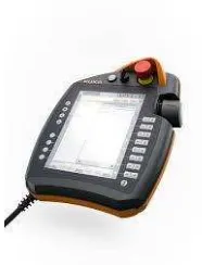
Figure 1.1: ABB Teach Pendant Figure 1.2: KUKA Teach Pendant
Figure 1.3: FARA Teach Pendant
However, there are one device that has movement, voice and gesture recognition that hit the market last year 2010, called Kinect. It is released by Microsoft and is applicable for Windows and Xbox for gaming purposes. However, the price for a piece of Kinect is RM 465 internet price. In contrast, the Leap Motion controller is just cost RM 250 including shipment fee. Moreover, it is easy to use by just using the hand gesture rather than Kinect sensed the body movement to control. Thus, it is cheap and very convenient for the developers to explore. In conclusion, there is a huge potential for developers to expand this future to other audience who are excited to discover the potential of this Leap Motion controller created by the developers. As saying goes, “get your application into millions of hands or even more fingers”.
3
all those clicks and taps and drags and drops. The Leap Motion Controller sensed our hands and fingers and also followed every move it make. Our hands and fingers are allowed to move in the wide open space between the controller and the hardware.
The hardware for this project is a Leap Motion controlled robotic arm. The uses of robotic arm can be expanded to greater fields such as for the disabilities, in robotic industries, chemical laboratories, and accomplished tasks where human unable to reach. All this fields needed accuracy and precision to do the tasks, and Leap Motion has very fine system, with the servo actuated robotic arm able to perform such tasks given. Controlling a robotic arm using joysticks or buttons might be difficult, but using the natural and understandable movements and gestures, task is easily performed.
Objective of the Leap Motion is used because it is a new technology of controller able to bring the future in the whole new level of controlling. This will further expand well acceptance usage in robotic fields, despite its small in size, precise and it is a revolutionary way to control an object.
1.2 Problem Statement
In the industries, or in the laboratory which needed to handle stuff with care used robotic arm. The most likely issue that operator of the controller found out difficulties in using those control panels, manual book might be as thick as a textbook. Conventional controller also led to performing task slowly as the confusing buttons and joystick which is not synchronize with the way of the operator could imagine. Moreover, this kind of conventional controller need more time to adapt to the use of the buttons and joysticks to able to do task smoothly.
4
1.3 Objective
The main objectives of the project are embarked as below:
1. To develop Leap Motion gesture controlled robotic arm hardware. 2. To construct an algorithm using JavaScript to control the robotic arm.
3. To integrate a Leap Motion controlled robotic arm structure for pick and place purpose.
4. To analyze the accuracy and precision of the robotic arm and to improve its accuracy and pick and place performance.
1.4 Scope
5
6
CHAPTER 2
LITERATURE REVIEW
2.1 Introduction
Figure 1.1 above showed an ABB robotic arm controller. The joystick is the controller the movement of the ABB robotic arm. It is a conventional controller in the market now days. While the Figure 2.2 shows a black glove which is another controller to control a device or a machine. The robot controlling is done by Fusion of Hand Positioning and Arm Gestures using data glove [4]. It is necessary to wear the glove, thus limits it freedom although the precision is high. The weakness is that proper light and camera angle are required for capturing hand gesture correctly. An Electromyographic (EMG) signals are a famous way of collect the data from human arm motion by the movement of muscle in the most research [5]. A technique is needed to handle the light source and viewing angle to capture efficiently hand gesture [4]. But despite having all these available assisting tools, improvement for the aids assisting controller are still much needed.
7
2.2 Dark Glove with Colored Cues
The name of the robot is CRS A-460 with three-fingered gripper but is a manipulator graphic model simulator. The real time hand gesture able to guide the robotic arm in gripping gestures in the simulator. This robotic arm has six degree of freedom and it is operated with electric DC servo motors. Furthermore, to control the robotic with hand gestures is to wear a dark glove marked with colored clues on the dark glove. For the tracking the colored cues on the dark glove to capture images in sequence in real time, a single camera is used. The limitation is limited the operator’s freedom on need to wear a glove [6].
2.3 Simple Video Camera
8
2.4 A Camera
Camera also has another alternative method to control a robotic arm where consist of four-axis servo motor handmade used for the operation. There are two control modules robotic arm. The first is to compare all the pre-stored data in the database Template Matching Algorithm. Next is to find where the fingertips are and count the number of the same, use the Signature Signal. Both methods have short in the calculation, making it suitable for continuous frame capture sequence. To control the robotic arm gripper, local features used to provide hand gesture while global features hand position is 3D dimension. As for this case, the application of the robot hand control the robotic arm is followed the same path of the human hand. One limitation is that the shoulder position must be configured to the system manually before starting the system.
The experiment is tested under the same conditions light source light is on the left and in the corner at the hands of their fans. This type of source positions always because shadows on the object observed [7].
2.5 Kinect