UNIVERSITI TEKNIKAL MALAYSIA MELAKA
ENGINEERING DESIGN ANALYSIS ON 5KG PAYLOAD
GRIPPER FOR COMAU ROBOT
This report submitted in accordance with the requirements of the Universiti Teknikal Malaysia Melaka (UTeM) for the Bachelor Degree of Engineering Manufacturing
(Robotic and Automation) with Honours.
By
BONG KUAN FUNG
UTeM Library (Pind.1/2007)
UNIVERSITI TEKNIKAL MALAYSIA MELAKA
BORANG PENGESAHAN STATUS LAPORAN PSM
JUDUL:
ENGINEERING DESIGN ANALYSIS ON 5KG PAYLOAD GRIPPER FOR COMAU ROBOT
SESI PENGAJIAN: Semester 2 2008/2009
Saya BONG KUAN FUNG mengaku membenarkan laporan PSM / tesis (Sarjana/Doktor Falsafah) ini disimpan di Perpustakaan Universiti Teknikal Malaysia Melaka (UTeM) dengan syarat-syarat kegunaan seperti berikut:
1. Laporan PSM / tesis adalah hak milik Universiti Teknikal Malaysia Melaka dan
penulis.
2. Perpustakaan Universiti Teknikal Malaysia Melaka dibenarkan membuat salinan
untuk tujuan pengajian sahaja dengan izin penulis.
3. Perpustakaan dibenarkan membuat salinan laporan PSM / tesis ini sebagai bahan
pertukaran antara institusi pengajian tinggi. kepentingan Malaysia yang termaktub di dalam AKTA RAHSIA RASMI 1972)
DECLARATION
I hereby, declared this report entitled “ENGINEERING DESIGN ANALYSIS ON
5KG PAYLOAD GRIPPER FOR COMAU ROBOT” is the result of my own
research except as cited in the references.
Signature : ………
Author’s Name : BONG KUAN FUNG
APPROVAL
This report is submitted to the Faculty of Manufacturing Engineering of UTeM as a partial fulfillment of the requirements for the degree of Bachelor of Manufacturing Engineering (Robotic and Automation) with Honours. The members of the supervisory committee is as follow:
………
i
ABSTRACT
ii
ABSTRAK
Pencengkam merupakan penggunaan utama bagi tangan robot seperti mana pencengkam tersebut akan disambungkan pada penghujung sesebuah tangan robot untuk aplikasi tertentu bagi robot tersebut. Penggunaan gripper adalah luas dalam pelbagai operasi industri seperti pemindahan barangan, pemasangan, dan pengendalian dalam process pembuatan. Terdapat berbagai teknologi cara mekanisme untuk gerakkan tangan robot yang memberi kuasa bagi pergerakkan pencengkam. Contohnya, hidraulik, pneumatic, dan elektrik motor system adalah mekanisme penggerak yang umum digunakan. Dalam projek ini, analisis rekabentuk kejuruteraan terhadap 5kg muatan gripper untuk Comau robot akan dijalankan.
Analisis ‘finite element’ akan dilaksanakan bagi simulasi pesongan komponen
gripper apabila dikenakan muatan. Analisis tersebut penting bagi penentuan rekaan parameter. Selain itu, simulasi pergerakan ataupun dikenali sebagai ‘motion
simulation’ juga akan dijalankan. Sistem tersebut memberi paparan grafik dan
iii
DEDICATION
iv
ACKNOWLEDGEMENT
There are many people who deserve thanks for the contributions they have made to this project. Firstly, I would like to express my endless grateful to my Final Year
Project’s Principal Supervisor, Encik Khairol Anuar Bin Rakiman. He directed and
instructed me through every phase of the project, and his guidance has been invaluable. He also spent time and effort helping to resolve new issue by giving advice and suggestion as the project developed and checking the report a number of times.
vii
4.3 Combination Solution Principles to Fulfill the Overall Function 40 4.4 Technical Rating Rt and Economical Rating Re 42
4.5 Selection Suitable Combinations 45
4.6 Improvement Base on Solution Variants 47
viii
5.6.1.1 Moment Inertia of Holder with Jaws 67
5.6.1.2 Force Acting on Robot Mount 69
5.6.1.3 Force Acting on Gripper Mount 70
5.6.1.4 Force Acting on Bracket 70
6.1 Further Improvement Works and Suggestion 85
ix
APPENDICES
x
LIST OF TABLES
Table 2.1. Summarize of part characteristics and associated end
effector solutions. 14 Table 2.2a. Lower Power Actuator Principles. 20 Table 2.2 b. Comparison between common actuators. 21
Table 4.1 Existing griper parts and function. 39
Table 4.2 Combination scheme for different solution principle. 41
Table 4.3 Technical rating for variants. 43
Table 4.4 Economic rating for variants. 43
Table 4.5 Operation sequence for existing gripper design. 50 Table 4.6 Operation sequence for new gripper’s jaw design. 52
Table 5.1 New gripper parts and function. 60
Table 5.2 Parts quantities and weights. 61
Table 5.3 Cylinders characteristic and specification. 64
Table 5.4 Evaluation on cylinders. 65
Table 5.5 Result of base design analysis. 77
xi
LIST OF FIGURES
Figure 2.1. Types of gripper action. 6
Figure 2. 2. External griping action. 8
Figure 2.3. A classification of the basic end effectors types. 8
Figure 2.4. A noncontact end effector for acquiring and transporting delicate wafers. 9
Figure 2.5. Compliant pneumatic gripper executes a gentle wrap grasp. 10 Figure 2.6. A gripper with pivoted fingers designed. 11
Figure 2.7. Two-finger servo gripper with force sensing and changeable fingertips. 12
Figure 2.16. (a) Adjustable jaw with laminated plate cams. (b) Flexibility of jaw stacks arrangement. (c) Gripping odd shaped work piece. 29
Figure 2.17. Magnetic gripper, handling ferromagnetic workpieces. 30
Figure 2.18. Type of vacuum gripper. 30
xii
Figure 3.1 Flow of Work for Design and Analysis Process. 34
Figure 4.1 Existing gripper design. 38
Figure 4.2 Comparison of the technical and economic rating of the
concept variants. 44
Figure 4.3 Selection of combinations of solution principles (variants). 46
Figure 4.4 Optimization on gripper’s jaw. 51
Figure 4.5 Bottom view of gripper’s jaw arrangement. 52 Figure 4.6 Optimized gripper operates with roller conveyor. 53
Figure 4.7 Holder. 54
Figure 4.8 Rubber pad. 55
Figure 5.1 Conceptual design. 57
Figure 5.2 Forces acting on gripper. 62
Figure 5.3 Rotation of holder. 67
Figure 5.4 Force acting on robot mount. 69
Figure 5.5 Force acting on gripper mount. 70
Figure 5.6 Force acting on bracket. 70
Figure 5.7 Force acting on support. 70
Figure 5.8 Force acting on base. 71
Figure 5.9 Force acting on holder. 71
Figure 5.10 Force acting on slider. 72
Figure 5.11 Force acting on jaw. 72
Figure 5.12 Force acting on rod. 72
Figure 5.13 Forces acting at the base. 73
Figure 5.14 Stress occur on base due to applied forces. 74 Figure 5.15 Displacement changes due to applied forces. 75 Figure 5.16 Strain analyses due to applied forces. 76
xiii
1
CHAPTER 1
INTRODUCTION
1.1 Overview
According to dictionary of McGraw-hill˄2003˅, gripper is define as a component of robot that grasp an object, generally through the use of suction cups, magnets, or articulated mechanism. Gripper provides the capacity to do a wide variety of manipulative task. Robotic hand or gripper is the integral part in most of the robot application. A robot arm itself can serve no purpose until a load or a tool is suspended from or attached to it. The robotic application in assembly and material handling is growing more rapidly in industrial environment. Thus, design of robotic gripping mechanism always becomes the key element for a specific operation.
2
The gripper is the mechanical interface between the robot and the work and the device with which the robot performs its programmed handling functions. Correctly selecting the gripper for an application is essential to the success of the application. Arthur G. Erdman (1986) explained that gripper selection is a may not be an easy task since there are wide variety of gripper types and configurations and many different factors to consider. Information on the factors which are relevant to the selection process is incomplete and tends to be qualitative. The material available and ease or manufacturing is also an important consideration.
In this study, a robot gripper that has been design by the previous students is required be to fully analyses for its physical properties when handling load. Solid Work will be use as the analysis software for finite element analysis to the gripper. Finally, the gripper has to go through workspace testing by using simulation software to observe its performance in real time working situation.
1.2 Problem Statement
The design analysis of robotic gripper is highly complex and environment dependent. To deal with complexity, the entire design project has to be broken down into several sub problems which are then treated independently as optimization problem. However, the constraints are generally dependent on each other. Its also appear that more than one constraint have to be minimize simultaneously. It may require minimize weight of gripper and the stability of the grasp.
3
Often, very little time is spent in optimal kinematics structure design in the early stages of a design process. D. T. Pham (1988) describes that a time pressures sometimes force engineers to repeat topologies that have worked in similar application in the past rather than try to create better design. It is always encourages to follow the previous design unless the design analysis really proven that it was not good. Thus, modification and optimization are requires to upgrade the design to achieve a better performance.
Generally, a physical prototype is necessary to truly test a hand’s ability to perform tasks, but this can be quite costly and design changes are not easy to make. Thus it would need a simulation system that able to load a gripper hand design, to interact with it and perform grasps of objects, and to visualize and evaluate the space of performance and error that might occurs.
1.3 Objectives
The objective of this project is to design analysis the existing design gripper to perform a pick and place operation for 5kg payload boxes. Below are important objective has to be achieved:
a) Analysis on existing design
4
1.4 Scope
The scope is focused on related aspect in this project so that the objectives are able to accomplish. Scope on this project will cover up the below task:
a) Improvement on existing design or drawing.
5
CHAPTER 2
LITERATURE REVIEW
2.1 Overview on Gripper
A gripper is a device that grasps, retains and eventually releases a workpiece. It can hold, tighten, handle and release an object just like a human hand. It can be attached to a robot or be part of a fixed automation system. Because this component handles the workpiece, the gripper must be selected and applied carefully. The design and construction of highly dexterous robot hands has been a major research and development objective for at least the past two decades. It was inspired by the well-known Utah/MIT robot hands during the 1980’s explained by S .C. Jacobson (1986).
6 2.2 Gripper Operation
Consider an object grasped at a contacts, it is generally assumed that all contacts are point contacts and idealizations such as a line or surface contact can be approximated by two ore more point contacts. Each point contact can be modeled as either a frictionless point contact, a frictional point contact, or a soft contact. A frictionless contact is defined as a contact in which the finger can only exert force along common normal at the point of contact. A frictional contact is contact that can transmit both a normal force and a tangential force at the point of contact. While soft contact also allows the finger to exert a pure torsion moment about common normal at the point of contact.
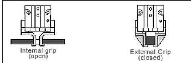
2.3 Gripping Action
2.3.1 Internal Gripping
In some applications, the object geometry or the need to access the exterior of the object will require that the object is held from the center. In this case the opening force of the gripper will be holding the object. Figure 2.1 below shown an internal and external grip.
7
2.3.2 External Gripping
This is the most popular method of holding objects, it is the most simplistic and it requires the shortest stroke length. When the gripper jaws close, the closing force of the gripper holds that object.
External gripping action can be classified into two categories as shown in Figure 2.1.
2.3.2.1 Friction Gripping (Force Closure)
Friction gripping relies totally on the force of the gripper to hold the part. They are the easiest to fabricate and may require more force to hold the object. This is especially useful for objects that do not have flat surfaces. Parts can be removes by forces applied from any direction. The coefficient of friction between the workpiece and the gripper fingers can vary greatly depending on the material and surface finish. For consistency in sizing purpose, the recommended coefficient of friction always is 0.25. Force closure is also known as frictional contact since it transmits both a normal force and a tangential force at the point of contact.
2.3.2.2 Retention or Encompassing Gripping (Form closure)