UNIVERSITI TEKNIKAL MALAYSIA MELAKA
DESIGN AND ANALYSIS OF ROBOT
GRIPPER FOR 10 KG PAYLOAD
Report submitted in accordance with partial requirements of the Universiti
Teknikal Malaysia Melaka for the Bachelor of Manufacturing Engineering
(Robotics & Automation)
By
Samson Khoo Hock Chye
i
DECLARATION
I hereby declare that this report entitled “DESIGN AND ANALYSIS OF ROBOT
GRIPPER FOR 10 KG PAYLOAD” is the result of my own research except as
cited in the references.
Signature :
Author’s Name : DESIGN AND ANALYSIS OF ROBOT GRIPPER FOR 10 KG PAYLOAD
APPROVAL
This report is submitted to the Faculty of Manufacturing Engineering of UTeM as a partial fulfillment of the requirements for the degree of Bachelor of Manufacturing Engineering (Robotics and Automation). The members of the supervisory committee
are as follow:
………..
iii
ABSTRACT
ABSTRAK
Projek Design and Analysis of Robot Gripper for 10 kg Payload in terbahagi kepada dua bahagian utama. Bahagian pertama projek ini berkenaan dengan cadangan projek manakala bahagian kedua adalah berkenaan dengan implimentasi projek. Laporan ini menerangkan tentang kombinasi kedua-dua bahagian tersebut, dimana ia mengandungi lima bab, bermula dengan pengenalan, kajian ilmiah, metodologi, keputusan, perbincangan, dan berakir dengan kesimpulan. Bab pertama menerangkan skop dan objektif projek dan keputusan yang dijangka. Objektif utama projek ini adalah untuk merekabentuk dan menganalisa Robot Gripper yang boleh mengangkat bebean 10 kg. Manakala, bab kedua menerangkan tentang kajian ilmiah mengenai proses merekabentuk dan menganalisa Robot Gripper. Bab ketiga pula menerangkan tentang cara-cara projek ini dilaksanakan. Projek ini bergantung sepenuhnya kepada penggunaan program SolidWorks untuk menganalisa dan merangsang pergerakan
v
DEDICATION
ACKNOWLEDGEMENTS
This report inevitably involves many helping hands. First of all, I am extremely grateful and thanks to my supervisor, Mr. Khairol Anuar B. Rakiman, for all the guidance and critics given to me directly or indirectly, and also his scarification in time to teach and explain to me without a word of complains.
vii
List Of Abbreviations, Symbols, Specialized Nomenclature .………..……xiii
1. INTRODUCTION…………..……….1
1.1Introduction ……….1
1.2Objective ………….………2
1.3Scope ………..……….2
2. LITERATURE REVIEW ………...…....4
2.1Introduction ……….………4
2.2Industrial Robot……….………...6
2.3Gripper Types ………..6
2.4Driving Force for Gripper………..11
2.4.1 Electrical System ………..11
2.4.2 Pneumatic ……….12
2.4.2.1Pneumatic Valve Consideration ………12
2.4.3 Vacuum ………13
2.4.4 Hydraulics ………14
2.5Theory of Gripper Design ……….14
2.5.1 Process and Environment ……….15
2.5.3 Payloads ………...18
2.5.3.1Payload Force Analysis ……….19
2.5.3.2Grip Force Requirement ………21
2.5.4 Gripper Design Procedure ………24
3. METHADOLOGY ………...……26
4. RESULTS AND DISCUSSION ………...……...32
4.1 Preliminary Design ………...32
4.3.4. Final Material Selection ……….………39
4.4 Stress Analysis ………..………41
4.5 Actuator Selection ………..………...48
4.6 Gripper’s Specification ……….………50
4.7 Gripper’s Working Condition ………...51
5. CONCLUSION ………...…………..55
ix APPENDICES
A Engineering Drawing For Gripper B-1 Stress Analysis For Base
B-2 Stress Analysis For Main Structure Bar B-3 Stress Analysis For Holding Bar B-4 Stress Analysis For Control Bar
LIST OF FIGURES
2.1 Parallel Jaw Gripper 7
2.2 Angular Jaw Gripper 8
2.3 Four-bar Linkage Jaw Gripper Type 10
2.4 Multiple Jaw Chuck Type 10
2.5 Four-way Valve Connection 13
2.6 Process Flow Chart 16
2.7 Typical Robot End Arm 18
2.8(a) Payload Force and Moment for X-Z plane 20
2.8(b) Payload Force and Moment for X-Y plane 20
2.9 Encompassing Grip 23
3.1 Methodology Flow Chart 28
4.1 Dimensions of Standard Commercial Rice Bag 33
4.2 The Sketch Development of Gripper Design 34
4.3 Final Design of Gripper 35
4.4 Components of Press Bar 36
4.5 Restrain Location for Holding Bar 41
4.6 Load Location for Holding Bar 42
4.7 Stress for Holding Bar 43
4.8 Displacement for Holding Bar 44
4.9 Deformation Shape for Holding Bar 45
4.10 Design Check for FOS 46
4.11 Pneumatic Actuator in Extended Position 49
4.12 Pneumatic Actuator in Retracted Position 49
4.13 Gripper Approaching Rice Bag 51
4.14 Gripper Grasping Rice Bag 52
4.15 Gripper in Close Condition 53
xi
LIST OF TABLES
2.1 Summary of Gripper Types 9
3.1 Project Planning for PSM 1 30
3.2 Project Planning for PSM 2 31
4.1 Item Number and Part Name 36
4.2 Material and Its Estimated Assembly Weight 38
4.3 Material and Its Yield Strength Value 39
4.4 Gripper’s Component and Its Material 40
4.5 Stress Value for Holding Bar 43
4.6 Displacement Value For Holding Bar 44
4.7 Summary of Stress Analysis for Gripper 47
LIST OF ABBREVIATIONS, SYMBOLS, SPECIALIZED
NOMENCLATURE
GM - General Motors DC - Direct Current PSM - Projek Sarjana Muda kg - Kilograms
mm - Milimeters lb - Pounds lbf - Pounds x Feet
N - Newton
N/m2 - Unit for yield strength of material, 2
Meter Newton
UTeM - Universiti Teknikal Kebangsaan Malaysia Melaka FOS - Factor of Safety
1
CHAPTER 1
INTRODUCTION
1.1
Introduction
A robot gripper is an end-effector or sometimes called end-of-arm tooling that is used on industrial robots for material handling, e.g. grasping, holding, lifting, moving and controlling materials. Robot grippers are very important tools because without it, industrial robot cannot be used in material handling applications.
Robot grippers are meant to replace human hands because they are very good for repetitive cycles, handling heavy loads, and operate under extreme temperatures and environments where human hands cannot operate. Since robot grippers are usually custom designed for its particular applications, this project will discuss in detail about the design of a robot gripper specifically designed for pick and place application of a standard commercial 10 kg rice bag.
1.2
Objective
The main objective of this project is to design and perform analysis on a robot gripper specifically for the use of material pick and place application. This robot gripper will be handling rice bags with the load of 10 kg. This is objective can be achieved with the aid of simulation software. On top of that are some additional objectives that are related to this project:
a) To conduct research on the topic that is related to this project.
b) To implement the knowledge gained from the research to design a robot gripper that is able to pick and place rice bags with 10 kg load. c) To conduct full finite analysis of the design.
d) To produce complete assembly drawing of the robot gripper. e) To run simulation on the gripper’s working condition.
1.3
Scope
Since designing a robot gripper is a vast and wide title, the scope for this project has been scaled down so that the project’s objectives can be achieved. First and foremost, this project will cover:
a) Design of a robot gripper that is able to pick and place standard commercial 10 kg rice bags from conveyor to stacking pallet for stacking purposes. b) Finite analysis of the design such as movement analysis and material stress
for the load that the gripper will handle. This is done with the help of design software such as CATIA or SolidWorks.
c) Producing a complete engineering drawing for the final assembly of the robot gripper.
3
Stated above are the scopes that are covered in this project. As for the robot gripper, there are certain requirements that this gripper needs to meet. They are:
a) The gripper must be able to pick and place standard commercial 10 kg rice bags with general size of approximately 51 cm x 40 cm x 9 cm (L) x (W) x (H).
b) The gripper must be strong enough to pick and place the commercial rice bags but it must also be gentle so that it will not puncture or cause damage to those bags in the process.
c) The gripper must be designed so that it can be attached to COMAU SMART NS ROBOT ARM model robot that is available in the Manufacturing Faculty’s Lab.
CHAPTER 2
LITERATURE REVIEW
2.1
Introduction
This chapter describes the literature review that is done to gain more information on this project. The beginning part of this chapter explains the history of Industrial Robots and types of robots that are available. This will be followed by information pertaining robot grippers or end effectors. Finally, information on gripper design consideration will be available at the end of this chapter.
An industrial robot is officially defined ISO [1] as an automatically controlled, reprogrammable, multipurpose manipulator programmable in three or more axes. The modern concept of industrial robotic manipulators was only introduced in late 1950s by G. C. Devol (U.S. Patent 2988237) and later joined by J. Engelberger to start up Unimation Inc. They are the originators of the first industrial robot by Unimation Inc. in the 1959. The first installation of the Unimate robot for loading/unloading a die-casting machine at GM was in 1961 [2].
5
There are many types of industrial robots that are being used in industries nowadays. A simple example is an industrial robot manipulator with six degrees of freedom. It has the features of a human chest, upper arm, forearm and wrists respectively [3]. Therefore, it can be said that robots are designed to emulate human hand. The only difference is that it is much bigger compared to human hand.
Same as humans, industrial robots needs some sort of device so that it can interact with the world around it in a form of grasping, manipulating parts and so on. This device is called robot gripper or sometimes called end effectors or end-of-arm tooling [5]. End effectors should not be considered as accessories, but as a major component in any industrial robot application. Proper selection and design of end effectors can make the difference between success and failure in many process applications, particularly when one includes reliability, efficiency, and economic factors. End effectors consist of the fingers, the gripper, and the wrist.
According to the Robotic Industry Association, there are currently over 118,000 robots being used in the United States alone. The industry has seen significant growth over the past five years, having record sales in 1999 and 2000 with new unit sales exceeding one billion dollars in the year 2000 [6].
Since cost of grippers may be as high as 20% of a robot’s cost, depending on the application and part complexity [7], no wonder robotic grippers are a $ 31M industry [6]. Engineers and designers are striving very hard to keep the cost of robotic grippers as low as possible. Therefore, developing a multipurpose gripper is not a good solution because it involves exaggerated cost. This is one of the main reasons why grippers are design for specific application only. This is to ensure that simple design can be produced, thus cutting the initial cost for an automation system.
2.2
Industrial Robot
All common commercial industrial robots are serial-link manipulators, usually with no more than six kinematically coupled axes of motion. By convention, the axes of motion are numbered in sequence as they are encountered from the base up to the wrist. The first three axes account for the spatial positioning motion of the robot. Their configuration determines the shape of the space through which the robot can be positioned. Any subsequent axes in the kinematic chain generally provide rotational motions to orient the end of the robot arm and are referred to as wrist axes. There are two primary types of motion that a robot axis can produce in its driven link, either revolute or prismatic. It is often useful to classify robots according to the orientation and type of their first three axes [3], [8], [9], [14].
Robot component consists of:
7
The most commonly used grippers are finger grippers. These grippers generally have two opposing fingers or three fingers like a lathe chuck. The fingers are driven together such that once gripped any part is centered in the gripper. This gives some flexibility to the location of components at the pick-up point. Two finger grippers can be further split into parallel motion or angular motion fingers.
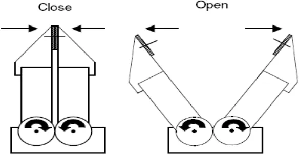
Angular jaw gripper open and close around a central pivot point, moving in an arcing motion. An angular gripper is used when there is a need to get the tooling out of the way. The advantage for an angular gripper falls on its simple design and only requires one power source for activation. However, it has several disadvantages including jaws that are not parallel and a changing centre of grasp while closing.
Meanwhile, parallel jaw gripper moves in a motion parallel in relation to the gripper’s body. A parallel gripper is used for pulling a part down inside a machine because the fingers fit into small areas better. An advantage of parallel type gripper is that the centre of the jaws does not move perpendicular to the axis of motion. Thus, once the gripper is centred on the object, it remains centred while the jaws close. Space constraints might lead to the use of parallel over angular [4], [10], [11], [12], [13]. Figure 2.1 and Figure 2.2 shows the Parallel Jaw and Angular Jaw Gripper.
Figure 2.1: Parallel Jaw Gripper
Figure 2.2: Angular Jaw Gripper
9
Table 2.1: Summary of Gripper Types
Type Application/Ideal
Magnetic Sheet metal Electro-magnet picks-up ferrous objects
Magnetic field
Needle Fabrics Sharp pins
extend/retract at opposing angles
Cam
Expansion Glassware Inflatable bladder expands inside cavity
Air pressure
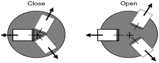
Figure 2.3: Four-bar Linkage Jaw Gripper Type
Meanwhile, the second type is the multiple jaw/chuck style. The gripper’s jaws operated similarly to a machine tool multi-jaw chuck as seen in lathe machine chuck. This gripper is suitable for holding round and rod-like objects. The disadvantage however for this type of gripper is that its design caused it to become heavier and its limited to certain application only [10].