i „I approve that I have read this thesis thoroughly and in my opinion, this thesis has fulfilled the criteria covering all the aspects of scope and quality and satisfied to be
awarded for Bachelor of Mechanical Engineering (Design and Innovation).‟
Signature :………
Supervisor :………
MOHD SYAFIQ BIN AHMAD ROSELI
This report is written as a partial fulfillment of terms in achieving the award for Bachelor of Mechanical Engineering (Design and Innovation)
Faculty of Mechanical Engineering Universiti Teknikal Malaysia Melaka
ii “I admit that this report is all written by myself except for the summary and the article which I have stated the source for each of them.”
Signature :……….
Writer :……….
iii DEDICATION
iv ACKNOWLEDGEMENT
In this great opportunity, I would like to thank Allah for providing me strengths to finish up this project and finally it was completed. Here, I would like to acknowledge and appreciate all those people who helped and guided me till this phase of this project.
In a particular, I would like to express my gratitude to my supervisor, Mr Mohd Rizal B. Alkahari for giving me a chance to do the project under his guide and attention. I also would like to thank all of my colleagues whether in UTeM or not for their contribution in sources, journal and a whole lot of studying tools provided by them. I am gratified to the Head of Department of Mechanical Engineering (Design and Innovation) and the members of the staff at the University the constant encouragement and the valuable inputs from time to time throughout the completion of this report.
In this semester where PSM subject had take place, I had gain a lot of valuable experience and knowledge that cannot be learnt inside a classroom only. Teamwork and endurance with an addition of creativity is a must in getting through the real life of an engineer and that is what I had learnt throughout all the completion of this PSM report and it will be forever be kept as a message deep in my heart and my mind.
v ABSTRAK
vi ABSTRACT
vii TABLE OF CONTENT
TITLE PAGES
DECLARATION i-ii
DEDICATION iii
ACKNOWLEDGEMENT iv
ABSTRAK v
ABSTRACT vi
CONTENT vii
LIST OF TABLE x
LIST OF FIGURE xii
LIST OF APPENDICES xiv
CHAPTER 1 INTRODUCTION 1
1.1 Problem Statement 2
1.2 Objective 2
1.3 Scope 2
CHAPTER 2 LITERATURE REVIEW 3
2.1 Introduction 3
2.2 Assembly Evaluation Method (AEM) 4
2.2.1 The Evaluation Procedure 5
2.2.2 The Hitachi‟s AEM Method Example 7
2.3 The Lucas Method 8
2.4 The Boothroyd – Dewhurst Method 9
2.4.1 Procedure of DFMA 10
2.4.2 DFMA Software 16
2.4.2.1 DFA Software 17
viii 2.4.3 Boothyord – Dewhurst DFMA Example 19
2.5 Application of DFMA 24
2.5.1 Directed Technologies, Inc. (DTI) 24
2.5.2 Texas Instruments 26
2.6 The Firefighting Machine 28
CHAPTER 3 METHODOLOGY 30
3.1 Introduction 30
3.2 Project Outline 31
3.2.1 Literature Review 32 3.2.2 Selection Design 32 3.2.3 CAD Drawing (Detail Design) 32 3.2.4 Manual DFMA Analysis Approach 33 3.2.5 Computer Aided DFMA Analysis 35
Approach (DFA and DFM software)
3.2.6 Comparison 35
CHAPTER 4 MANUAL DFMA ANALYSIS APPROACH 36
4.1 Introduction 36
4.2 Analysis of the Current Design (Manual) 36 4.2.1 Assembly Flow Chart 38 4.2.2 The Process and Material Selection 39 4.2.3 Theoretical Part Count and 50
Symmetrical Analysis Table
4.2.4 Handling and Insertion Time 54 4.2.5 Costing (Current Design) 76 4.3 Analysis of the Improvement Design (Manual) 78 4.3.1 Assembly Flow Chart 79 4.3.2 Theoretical Part Count and 81
ix 4.3.3 Handling and Insertion Time 85 4.3.4 Costing (Improved Design) 100
CHAPTER 5 COMPUTER AIDED DFMA ANALYSIS 102 APPROACH
5.1 Introduction 102
5.2 Analysis of the Current Design (Software) 102 5.2.1 Design for Manufacture (DFM) 103
Concurrent Costing
5.2.2 Design for Assembly (DFA) 108 5.3 Analysis of the Improved Design (Software) 111 5.3.1 Design for Manufacture (DFM) 111
Concurrent Costing
5.3.2 Design for Assembly (DFA) 113
CHAPTER 6 DISCUSSION 115
6.1 Introduction 115
6.2 Comparison between DFMA Manual and 115 DFMA Software
6.3 Parts Count 117
6.4 Part Removed 119
6.5 Improved Part 122
CHAPTER 7 CONCLUSION AND RECOMMENDATION 128
7.1 Conclusion 128
7.2 Recommendation 129
7.3 References 130
x LIST OF TABLES
NO. TITLES PAGE
2.1 For One Hand Manual Handling 13
2.2 For One Hand with Grasping Aids Manual Handling (second) 13
2.3 For Two Hand Manual Handling 14
2.4 For Two Hands or Assistance Required For Large Size 14 2.5 Manual Insertion (Part Added But Not Secure) 15 2.6 Manual Insertion (Part Secure Immediately) 15 2.7 Manual Insertion (Separation Operation) 16 2.8 Evaluating the design efficiency of Piston 21 2.9 Evaluating the design efficiency of the re-designed piston 23 2.10 Results of DFMA redesign of reticle assembly 28 3.1 Table for computation of Design efficiency 34 4.1 Fire Fighting Machine Body Theoretical Part Count 50 4.2 Fire Fighting Machine Strut Theoretical Part Count 52
4.3 Symmetrical Analysis 53
4.4 Handling and Insertion Time 55
4.5 Costing of fire fighting machine current design 76 4.6 Fire Fighting Machine Body Theoretical Part Count 81 4.7 Fire Fighting Machine Strut Theoretical Part Count 83
4.8 Symmetrical Analysis 84
4.9 Handling and Insertion Time 86
xi 6.3 The number of current parts and new parts 117
6.4 Description of parts removed 119
xii LIST OF FIGURES
NO. TITLES PAGES
2.1 The Hitachi‟s AEM procedure 5
2.2 Assemblability evaluation and improvements 7
2.3 The Lucas DFA procedure 9
2.4 Typical steps taken in a DFMA study using DFMA software 10
2.5 Example the value of α and β are calculated. 12
2.6 Example DFA software applications. 17
2.7 Example DFM software applications. 18
2.8 A piston-assembly design 20
2.9 An improved piston design 22
2.10 Exploded view of a fuel cell stack 24
2.11 Illustration of the manufacturing process for creating the gas 25
diffusion layer (GDL) 2.12 Original design for reticle assembly for thermal gunsight 26
2.13 An Improved Piston Design 27
2.14 The Firefighting Machine 28
2.15 Fire Fighting Machine Classification 29
3.1 Process Flow Chart 31
4.1 Assemble drawing before Improvement 37
4.2 Fire Fighting Body and Fire Fighting Strut 37
4.3 Assembly Chart for Fire Fighting Machine Body 38
4.4 Assembly Chart for Fire Fighting Machine Strut 39
4.5 Process for Cutting, Bending, Welding 40
4.6 Process for Cutting, Stamping, Bending 41
4.7 Process for Cutting and Bending 42
xiii
4.9 Process for Cutting 44
4.10 Process for Injection Molding 45
4.11 Process for Cutting, Metal Forming 46
4.12 Process for Powder Metallurgy 47
4.13 Process for Welding 48
4.14 Process for Inspection and Attach 49
4.15 Assemble drawing after Improvement 78
4.16 Fire Fighting Body and Fire Fighting Strut after Improvement 78 4.17 Assembly Chart for Fire Fighting Machine Body 79 4.18 Assembly Chart for Fire Fighting Machine Strut 80
5.1 Step in DFM Concurrent Costing 103
5.2 Library Operations 104
5.3 Result for Nozzle Header 105
5.4 DFA classification 108
xiv LIST OF APPENDICES
NO. TITLES
A Manual Handling Table Manual Insertion Table
B Analysis Total Current Design Analysis Total New Design
C Assembly (Current Design) Assembly (New Design)
CHAPTER 1
INTRODUCTION
Design for Manufacture (DFM) is a systematic approach that allows engineers to anticipate manufacturing costs early in the design process, even when only rough geometries are available on the product being developed. Design for Manufacture provides guidance in the selection of materials and processes and generates piece part and tooling cost estimates at any stage of product design. DFM is a critical component of the DFMA process that provides manufacturing knowledge into the cost reduction analysis of Design for Assembly.
life. The fireman needs to fast response to the situation without danger they own life. Therefore Fire Fighting machine have been develop at certain country to encounter this problem. In future, this machine may develop in large quantity. It may take a lot cost and time causes by certain complex part in that machine. Current number of part in this machine 61parts (part that same shape and dimension is classified as one part), so that the number of parts need to reduced. Here DFMA method will apply to this machine to encounter this problem. So by the reducing the number of part, it will easier during the manufactured.
1.2 OBJECTIVE
The objectives for the project are:
To improve current design of fire fighting machine utilizing DFMA approach To reduce overall cost of fire fighting machine through design improvement
1.3 SCOPE
There are several scopes for this project which is:
To conduct literature review of Fire Fighting technology and DFMA application. To apply Design for Assembly (DFA) and Design for Manufacturing (DFM) methodologies on Fire Fighting Machine.
CHAPTER 2
LITERATURE REVIEW
2.1 Introduction
In the 1960‟s and 70‟s, various rules and recommendation were proposed in order
to help designer consider assembly problems during the design process. Many of these rules and recommendations were presented together with practical examples showing how assembly difficult could be improved. However, it was not until the 1970‟s that numerical evaluation method were developed to allow design for assembly studies to be carried out on existing and proposed design.
The first evaluation method was developed at Hitachi and was called the Assembly Method (AEM). This method is based on the principal of “one motion for one
part.” For more complicated motions, a point-loss standard is used and the ease of
assembly of the whole product is evaluated by subtracting points lost. The method was originally developed in order to rate assemblies for ease of automatic assembly.
in United Kingdom. Unlike the Boothroyd Dewhurst method, the Lucas method is based on a “point scale” which gives a relative measure of assembly difficulty. Lucas DFA method definitely based on the parts count analysis stage with is known as terms “functional analysis”.
Starting in 1981, Geoffrey Boothroyd and Peter Dewhurst developed a computerized version of the DFMA method which allowed its implementation in a broad range of companies. For this work they were presented with many awards including the National Medal of Technology. [6]
2.2 Assembly Evaluation Method (AEM)
The Assimilability Evaluation Method (AEM) is developing by Hitachi as a result of trying to develop an automatic assembly system for tape recorder mechanism. After years of improvement, Miyakawa (1990) presented the „new‟ Assembly Evaluation Method from Hitachi. The improvements were e.g. the improvement assembly cost estimate accuracy for individual parts. This methodic formally known as Hitachi‟s AEM.
The method does not distinguish manual, automatic or robotic assembly. The reasons are the method is most beneficial when used in early conceptual stage and the manufacturing methods not decide yet.
design quality.
ii. Estimate assembly cost ratio, “K”.
[image:20.612.145.468.258.493.2]Used as relative index that compared the redesign to the estimated assembly cost of original design.
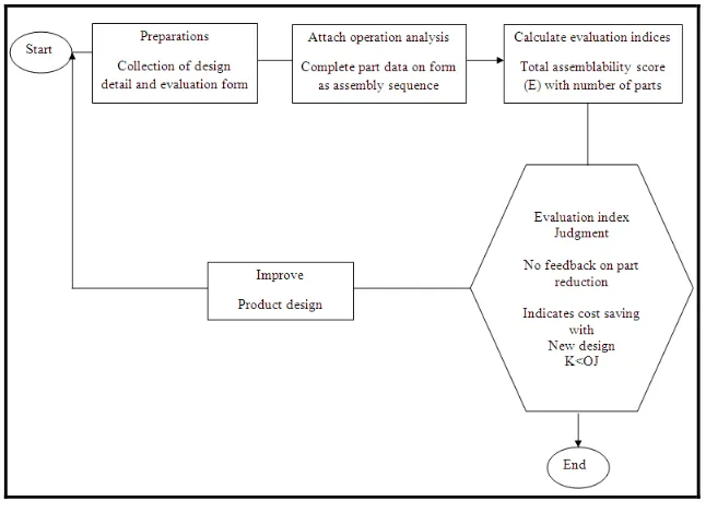
Figure 2.1: The Hitachi‟s AEM procedure
(Source: http://www.ami.ac.uk/ami4813_dfx/u03/s01/index.asp)
2.2.1 The Evaluation Procedure
The Hitachi AEM procedures are as per following sequence:
i. The analysis start by determine and categorized the assembly task sequence according by standard operation, that approximately 20 standard assembly task.
coefficients and subtracted from the best score.
iv. The totals then divided by the total number of parts. This may be able to consider a measure of design efficiency where a score of 100 would represent a perfect design.
v. Then the cost ratio, k is estimated continuously by compared to current assembly cost ratio with new design.
improvement of part.
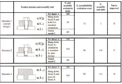
Figure 2.2: Assemblability evaluation and improvements (Source: Redford Alan, J. Chal, 1994)
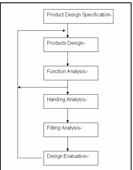
(DFA) of Boothyord Dewhurst Inc. (BDI), it is the result of the cooperation of Lucas Organization and the University of Hull in U.K. Now, the logic of Lucas DFA has been integrated in the engineering analysis software “TeamSet”. Lucas DFA separates the product design process into three stages: FA (Function Analysis), HA (Handing Analysis) and FA (Fitting Analysis). The relations of these three stages are shown as Figure 2.3.
Before the manufacturing and assembly process, the PDS (Product Design Specification) occurs which change the requirements of the customs into engineering specifications. After that, the design engineers perform the design job according to this information. This is a kind of process to change the engineering specifications into the real design and meanwhile, all the requirements should be satisfied. The Function analysis in Lucas DFA theory is to separates all the parts of the product into the essential parts and the non essential parts that employs very similar adjustment standard used by DFA.
Following the function analysis, comes the analysis of handing. Same as the function analysis, Lucas DFA separated the handing analysis into the automatic handing analysis and the manual analysis. During the fitting analysis, the sequence of parts assembly will be determined first, and then according to the assembly flow chat, analyze the gripping and the fitting process. After finishing the whole DFA analysis process mentioned above, the inadequate of the design will be highlighted, the revisal job occurs at this time. [10]
Figure 2.3: The Lucas DFA procedure (Source: Xiaofan Xie, 1995)
2.4 The Boothroyd – Dewhurst Method
Boothyord Dewhurst method design for manufacture and assembly is the well-known DFMA method that applicable for industry. The Boothyord-Dewhurst DFMA develops by Geoffrey Boothyord and Peter Dewhurst since 1982. The methods generally applied in industry particularly U.S industry. The methodology is well known for the industry especially US industry. The term “DFMA” is actually a trademark for Boothyord Dewhurst Inc. (BDI) the companies have created and develop the DFMA concept that used for their product development, the DFMA software system.