SUPERVISOR DECLARATION
" I hereby declare that the quality of the dissertation written is sufficient for the award of Bachelor of Mechanical Engineering (Design & Innovation)"
Signature Supervisor Date
' セ|@
.
: ...
: Siti Nurhaida binti Khalilキセᄋᄋᄋᄋ
ᄋᄋᄋᄋᄋᄋᄋᄋ@
: ...
_ZMNiNANlセNセMセMMMᄋᄋᄋᄋᄋᄋᄋᄋᄋ
ᄋ ᄋ@
DESIGN AND FABRICATION MODULAR PRODUCT WITH THE
INCORPORATION OF DIY ASSEMBLY METHOD: LAZY CHAIR
NUR 'AIN BINTI AZMI
This report is submitted as a partial fulfillment of the requirements for the
award Bachelor of Mechanical Engineering (Design & Innovation)
Faculty of Mechanical Engineering
Universiti Teknikal Malaysia Melaka
DECLARATION
"I hereby declare that the work in this dissertation is my own except for summaries and quotations which have been duly acknowledge"
Signature Author Date
/'
: ...
セ@
... .: Nur 'A in binti Azmi
':l_q Jl!N 2.0\4...
©
Unlverlltl Teknlkal Malaysia MelakllD edicated with love,
To my parents,
Azmi bin Hj. Arshad and Roziah binti Hj. Mustapha,
To my sister,
Nur Asyikin binti Azmi.
To all my friends.
IV
ACKNOWLEDGEMENT
Apart from the efforts of myself, the success of this project depends largely on the encouragement and guidelines of many others. I would like to take this
セーーッイエオョゥエケ@ to express my gratitude to the people who have been helping and
supporting me throughout the successful completion of this project.
First and foremost, I would like to thank my supervisor, Ms. Siti Nurhaida binti Khalil for the valuable guidance and advice right from the beginning of this project until the very end. Her willingness to motivate and encourage me contributed tremendously to my project and without her, this project would not have materialized.
I would like to express my greatest appreciation to my beloved parents, Azmi bin Hj. Arshad and Roziah binti Hj. Mustapha. I cannot thank them enough for their support, faith and loves towards me upon completing my project. They are the reasons for me to complete this project.
Last but not least, special thanks to Marliati Ghazali, Myn Samsuddin, Fariha Azmi, Nik Zubaidi and to all my friends who have been constantly helping and supporting me throughout the completion of this project. I am grateful with their helps and their contributions were vital for this project. Not to forget, thank you for the friendships.
v
ABSTRACT
VI
ABSTRAK
Objektif projek ini adalah untuk mengkaji aktiviti - aktiviti yang direka bentuk yang terlibat didalam proses mereka bentuk konsep modular produk yang baru bagi 'Kerusi Malas' dan fabrikasi sebuah prototaip dengan skala I :2 menggunakan bahan mampan. Modular produk yang baru ini juga harus menggabungkan konsep pemasangan 'DIY' . Projek ini bermula dengan memilih sebuah kerusi malas sebagai penanda aras dan idea-idea untuk reka bentuk konsep yang baru dapat dihasilkan. Carta morfologi digunakan sebagai salah satu kaedah untuk menghasilkan beberapa konsep rekabentuk yang baru. Kaedah pemlihan konsep yang digunakan adalah kaedah Pugh. Konsep reka bentuk yang dipilih akan dianalisis menggunakan kaedah DFMA untuk melakukan perbandingan dengan reka bentuk kerusi malas yang sedia ada. Analisis DFMA adalah salah satu cara atau aplikasi yang digunakan untuk mengurangkan bilangan bahagian atau komponen yang perlu dipasang menjadi satu produk dan meningkatkan kadar pemasangan yang mudah. DIY adalah bahagian yang paling penting dan cara pemasangan yang terbaik akan dipilih menggunakan kaedah pemilihan konsep yang ada di dalam Reka bentuk Kejuruteraan. Kaedah pemasangan DIY diaplikasikan di dalam reka bentuk ini adalah untuk member kesenangan kepasa para pengguna untuk memasang tanpa memerlukan bantuan manual. Hasil daripada projek ini adalah menghasilkan sebuah konsep modular produk yang baru untuk 'Kerusi Malas' bagi mengatasi beberapa masalah yang wujud dengan reka bentuk yang sedia ada.
Vll
TABLE OF CONTENT
CHAPTER CONTENT PAGE
DECLARATION 11
DEDICATION lll
ACKNOWLEDGEMENT lV
ABSTRACT v
ABSTRAK Vl
TABLE OF CONTENT Vll
LIST OFT ABLES Xl
LIST OF FIGURES Xll
LIST OF APPENDICES XlV
CHAPTER l INTRODUCTION l
1.1 Background
1.2 Objective 2
1.3 Scope 2
1.4 Problem Statement 3
1.5 Methodology 3
1.6 Outline of Report 3
1.7 Conclusion Remarks 5
CHAPTER2 LITERATURE REVIEW 6
2. 1 Modular Product 6
2.1.1 Defmitions 7
Vlll
2.1.3
Modular Architectures9
2.1.4
Modular Product Development II2.2
Do It Yourself (DIY) Method12
2.3
Design for Manufacture and Assembly14
(DFMA)2.4
Chair18
2.4.1
History of Chair18
2.4.2
Chair Seats19
2.4.3
Standards and Specifications19
2.4.4
Accessories21
2.5
Materials22
2.5.1
Softwood22
2.5.2
Plywood23
2.5.3
Stainless Steel24
2.5.4
Flexible Polymer Foam26
2.6
Threaded Fasteners28
2.6.1
Screw29
2.6.2
Bolt & Nut30
2.7
Conclusion Remarks31
CHAPTER3
METHODOLOGY
323.1
Introduction32
3.1.1
Benchmark34
3.1.2
Ideas I Sketches35
3.1.3
Generate Concept Design35
3.1.4
Concept Design Selection35
3.1.5
Product Architecture37
3.1.6
Configuration Design38
3. 1.7
Parametric Design38
3.1.8
Detail Design38
3.1.9
Prototype & Testing39
3.2
Flow of Design Process40
3.2.1
Defme Problem41
3.2.2 The House of Quality Configurations
3.2.3 Product Design Specification
3.2.4 Gather Information 3.2. 5 Product Decomposition 3.2.6 Morphological Chart
3.3 Conclusion Remarks
CHAPTER4 CONCEPT GENERATION
4.1 Introduction
4.2 Concept Design 1
4.3 Concept Design 2
4.4 Concept Design 3
4.5 Concept Design for Join Method
4.6 Conclusion Remarks
CHAPTER 5 CONCEPT DESIGN SELECTION
5.1 5.2 5.3
Introduction Pugh M ethod Pugh Method Chart
5.3. 1 Pugh Method: Lazy Chair Design 5.3.2 Pugh Method: Join Method
5.4 Conclusion Remarks
CHAPTER 6 DETAIL DESIGN
6.1 6.2 6.3 Detail Drawing Exploded Drawing Prototype
CHAPTER 7 RESULT & DISCUSSION
7.1 Result
7.1.1 DFA Analysis
7.2
7.3
7.1.1.2. DFA Analysis ofNew Design
7.1.2 DFM Analysis
Discussion
7.2.1 DFAAnalysis Result 7.2.2 Limitations and Strengths
7 .2.3 New Design of Lazy Chair
Conclusion Remarks
CHAPTER 8 CONCLUSION & RECOMMENDATION
8. 1
8.2
Conclusion
Recommendation
REFERENCES
APPENDICES
©
Unlverlltl Teknlkal Malaysia Melakll63
76
77
77
78
79
79
80 80
81
82
85
xu
[image:12.577.102.534.187.752.2]LIST OF FIGURES
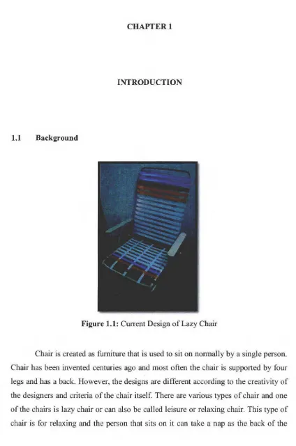
Figure 1.1: Current Design ofLazy Chair
Figure 2.1 : Designs of a drawer (Huang 2000) ... ... 7
Figure 2.2: Examples of Modular Product (Holtta-Otto 2005) ... l 0 Figure 2.3: Examples of Integral Product (Holtta-Otto 2005) ... l 0 Figure 2.4: DFMA approach ... 14
Figure 2.5: Example of DFM Concurrent Costing Software ... 15
Figure 2.6: Example of Design for Assembly software ... 16
Figure 2. 7: Chair design for comfort ... 20
Figure 2.8: Softwood description ... 22
Figure 2.9: Plywood description ... 23
Figure 2.10: Example's of stainless steel chair ... 24
Figure 2.11: Examples of seats made of flexible polymer foam ... 26
Figure 2.12: Wood screw ... 29
Figure 2.13: Bolt & Nut ... 30
Figure 3.1: Flowchart of Projek Srujana Muda ... 33
Figure 3.2: Existing design of lazy chair as benchmark ... 34
Figure 3.3: Example of Pugh Method selection method for a kettle ... 36
Figure 3.4: An overview of product architecture methodology ... 37
Figure 3.5: CATIA Software ... 39
Figure 3.6: Flow of Design Process (G. E. Dieter 2009) ... 40
Figure 3.7: CES EDUPACK 2011 ... 45
Figure 3.8: Example of Nickel alloys information from CES EduPack ... 46
Figure 3.9: Product Decomposition of existing design of Lazy Chair.. ... 4 7 Figure 4.1: Concept design 1 ... 49
Figure 4.2: Concept design 2 ... 50
Xlll
Figure 5. 1: Concept 2 as the final concept design ... 55 Figure 5.2: Final concept for join method which Concept 2 & Concept 3 ... 56
XIV
LIST OF APPENDICES
Appendix Al: Estimated Handling Time Table ... 86
Appendix A2: Estimated Insertion Time Table ... 87
Appendix A3: Axis of Orientation Chart ... 88
Appendix B 1 : Detail drawing ... 89
Appendix B2: Exploded drawing of Lazy Chair ... 90
Appendix B3: Exploded drawing ofThreaded Fasteners ... 91
Appendix C I : ISO view of Lazy Chair I ... 92
Appendix C2: ISO view of Lazy Chair 2 ... 92
Appendix C3: ISO view of Lazy Chair 3 ... 93
Appendix C4: ISO view of Lazy Chair 4 ... 93
Appendix Dl : Prototype of Lazy Chair 1 ... 94
Appendix D2: Prototype of Lazy Chair 2 ... 94
Appendix D3: Prototype of Lazy Chair 3 ... ... .. 95
Appendix D4: Prototype of Lazy Chair 4 ... ... .. 95
Appendix E l : Flow Chart for PSM I & 2 ... 96
Appendix F l: Gantt Chart for PSM 1 ... 97
CHAPTER I
INTRODUCTION
1.1 Background
Figure 1.1: Current Design of Lazy Chair
Chair is created as furniture that is used to sit on normally by a single person.
Chair has been invented centuries ago and most often the chair is supported by four
legs and has a back. However, the designs are different according to the creativity of
the designers and criteria of the chair itself. There are various types of chair and one
of the chairs is lazy chair or can also be called leisure or relaxing chair. This type of
chair is for relaxing and the person that sits on it can take a nap as the back of the
[image:15.577.103.527.104.744.2]2
chair is inclined and gives comfort to the user. It differs from other chairs because of the slant angle of the back of the chair.
Lazy chair in this project is design to counter several problems from its original design in terms of assemble the product. Using the modular product concept, a new concept design will be produced to overcome the problems. In general, modular product can be defined as an assembly with reduced parts, less complicated and easy to assemble. Modularization is a concept that offers competitive advantage to overcome complexity. Instead of manufacture a product with plenty of parts and mechanical fasteners, design a product using simple blocks which is easy to manufacture and use less joining method. The customers will be more satisfied and pleased with the easiness of assemble the product (Lupton 2006).
When the customers assemble the product themselves, the terms used for that act is Do It Yourself (DIY) method. DIY is an act of building or modifying without the help of any expertise and instead do it independently. Usually products with DIY assembly method will provide a manual for the customers to follow and DIY products are easy to assemble and use low cost tools (Howell2010).
1.2 Objective
To study the activities in designed involved in designing of a new modular product concept for " Lazy Chair" and fabrication of a prototype of scale l :2 using sustainable material. The modular product also has to incorporate "DIY" assembly method.
1.3 Scope
l. To propose few concept designs of modular product.
3
1.4 Problem Statement
The existing design of lazy chair does not imply the DIY concept. The chair already builds and joints completely and the buyers have to bring the chair in one piece. The chair inclination level can be adjusted according to the user's wish. The tricky part is that both of the rum rest must be moved simultaneously in order to change the inclination level. New modular conceptual design of lazy chair with the incorporation of DIY method will be produced at the end of this project to overcome problems of existing design.
1.5 Methodology
Methodology generally is a guideline for solving problems. In this project, there are several methods used to complete the design of new product. From the frrst steps until the end, the methods are represents in flow chart to make it easy to understand.
1.6 Outline of Report
Chapter 1 - Introduction
This chapter contains the background, objectives, scope and problem statement of the project. This chapter also reviews generally about the methods used in this project.
Chapter 2 - Literature Review
This chapter reviews the details of subjects cover in this project. The frrst subject is modular product and followed by DIY assembly method, DFMA, chair, materials and Screw, Bolt and Nut.
4
Chapter 3 - Methodology
This chapter contains the methods used in completing the project. The flow chart of this project is included in this phase and the details of each methods used is discussed.
Chapter 4 - Concept Generation
This chapter shows several of the concept designs generated from the previous morphological chart (In Chapter 3). The descriptions of each concept designs are also stated in this chapter.
Chapter 5 - Concept Design Selection
This chapter reviews the method used in selecting the best concept design. There are several methods that can be used, but in this project, the author chose Pugh Method as the concept design selection method.
Chapter 6 - Detail Design
5 Chapter 7 - Result & Discussion
This chapter discussed in details the results from the DFA and DFM analysis done manuaJly and the outcomes of this project.
Chapter 8 - Conclusion
This chapter will conclude all the results and fmdings that have been completed.
1. 7 Conclusion Remarks
In this chapter, the author reviews about the objectives, problem statements and scopes of this project. The author also reviews the outline of this report in general which consists of 8 chapters including this chapter. The background and history of the lazy chair are also discussed in this chapter generally as the details will be further discussed in the next chapter.
CHAPTER2
LITERATURE REVIEW
This chapter will discuss further on the project. The first subject to be discussed is modular product. The topics covered are the defmitions and advantages of modularity. This chapter also will discuss about the Do It Yourself assembly method, Design for Manufacture and Assembly and about the chair itself
2.1 Modular Product
[image:20.577.92.531.61.382.2]7
(a) (b)
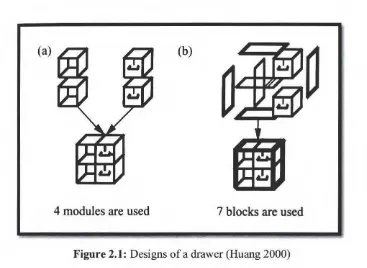
[image:21.577.136.503.51.319.2]4 modules are used
7 blocks are used
Figure 2.1: Designs of a drawer (Huang 2000)
2.1.1 Definitions
[image:21.577.116.517.308.744.2]Modularity is a common but unexplored thread among all areas of life-cycle engineering. It has become very famous in studies recent years though it has existed for at least 30 years. Modular products tend to have fewer components for assembly and therefore cheaper to assemble. Modularity has no specific definitions and in fact according to (Gershenson 2003), there is no agreement on the definition of modularity. Modular product can be defined in many ways and shown below in Table 2.1 are some examples of the definitions:
Table 2. 1: Definitions of Modular Product Authors
Pabl and Beitz
Ulrich and Tung
Definitions
Modular products refer to products, assemblies and components that fulfill varwus functions through the combination of distinct building blocks (Pahl 1988)
Defme modularity m terms of two characteristics of product design (Ulrich
Erixson and Kusiak
Chun Che Huang
1991):
1. Similarity between the physical
and functional architecture of the
design.
2. Minimization of incidental
interactions between physical
components.
Define modularity as a tool to decrease
assembly and manufacturing costs in
product families and manufacturing
systems (Erixson 1996).
The terms modularity in products is used
to describe the use of common units to
create product variants (Huang 2000).
8
In general, modular product is an assembly with reduced parts, less
complicated and easy to assemble. Due to the functional independence it creates,
modularization has been called the goal of good design (John K. Gershenson 1999).
2.1.2 Advantages of Modular Product
Modularity has a lot of advantages and benefits, as an example, modularity
allow the designer to control the degree to which changes in processes or
requirements affect the product. According to Ulrich and Tung (Ulrich 1991 ), they
described the benefits of modularity as:
l. Greater product variety. A modular product design can be partitioned
technically and variations in functional components can be substitutes
into modular architecture to create product variations based on
different combinations (Eggen 2003).
2. Economies of scale. Since each module will usually be produced in a
9
3. Ease of product updating. A modular product is decomposed into
modules; only certain modules need to be replaced. And for same
reason, upgrades, updates, maintenance and disposal are simpler.
4. Increased product variety. The use of modules means that a great
product variety can be achieved using different combination of
modules.
5. Reduced order lead-time. Since modules are manufactured in
relatively large scale, the production can be organized so as to reduce
manufacturing lead time.
6. Ease of design and testing. As the component is produced in modules,
the design is simple and for testing purpose, the components can be
tested individually.
Designing a modular product can gives the result of product cost and
development time higher or lower. If the designs are simple needs simpler
manufacturing process, the cost can be low but if the designs are complicated and
needs a lot interfaces between the modules, the cost may be higher. The development
time is often lower once the design is split into modules, where the design teams can
work in parallel on the different modules.
2.1.3 Modular Architectures
There are two types of product architecture; modular architecture and integral
architecture. An integral architecture includes a complex mapping from functional
elements to physical components (John K. Gershenson 1997). In the other hand,
modular architecture has a one-to-one mapping. Modular architecture allows a design
change to be made to one module without requiring a change to other modules for
the product function properly (Eggen 2003).
10
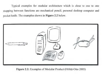
Typical examples for modular architecture which is close to one to one mapping between functions are mechanical pencil, personal desktop computer and pocket knife. The examples shown in Figure 2.2 below.
Figure 2.2: Examples of Modular Product (Ho ltUi-Otto 2005)
In the other hand, typical examples of integral architecture where it is hard to determine what part of a product performs which function are an old fashioned pencil, a laptop and a hunting knife. The examples shown in Figure 2.3 below.
[image:24.577.107.527.56.361.2] [image:24.577.111.523.413.602.2]<I
- '"1u0