i DESIGNING AND FABRICATION MODULAR PRODUCT WITH
THE INCORPORATION OF DIY ASSEMBLY METHOD (SHOE RACK)
NIK ZUBAIDI BIN NIK MAHMOOD
A thesis submitted in partial fulfillment of the requirement for the
Bachelor of Mechanical Engineering
Faculty of Mechanical Engineering (Design & Innovation) Universiti Teknikal Malaysia Melaka
ii DECLARATION
“I declare that this report entitle “Designing and Fabrication Modular Products with the Incorporation of DIY Assembly Method (Shoe Rack)” is the result of my own research except as cited in the references. The report has not been accepted for any degree and is
not concurrently submitted in candidature of any other degree”
iii Especially for my beloved mother
Nik Zakiah Binti Nik Idris
Also my beloved siblings Nik Zarina Binti Nik Mahmood Nik Zuhara Binti Nik Mahmood Nik Zakimah Binti Nik Mahmood
iv ACKNOWLEDGEMENTS
Praise and glory to Allah S.W.T, God of all creation and greetings and salutations we bring forth to our Prophet Muhammad S.A.W for overseeing this final year project with constantly guiding towards completion.
The author wishes and expresses the greatest appreciation to Miss Siti Nurhaida Bin Khalil as supervisor of this final year project. With their dedication and guidance, the project is able to be completed on time. Therefore, special thanks to them for the opportunity given and for the efforts towards the completion of this final year project.
The author wants to expresses his gratitude to the beloved family especially my mother for their support and commitment in the completion of this final year project.
Last but not least, the author would like to thank to the colleagues and to everyone parties who had been giving their hands either directly or indirectly to make this project a success and will be remember forever. The author also hopes that this project will be of benefit to the others that related to the Design and Innovation field, InsyaAllah.
v ABSTRACT
vi ABSTRAK
vii TABLE OF CONTENTS
CHAPTER TITLE PAGE
TITLE i
DECLARATION ii
DEDICATION iii
ACKNOWLEDGEMENT ix
ABSTRACT v
ABSTRAK vi
LIST OF TABLES ix
LIST OF FIGURES
LIST OF ABBREVIATION
1 INTRODUCTION
1.1 Background 1
1.2 Objective 3
1.3 Scope 3
viii
2 LITERATURE REVIEW
2.1 Introduction 5
2.2 Engineering Design Process 6
2.2.1 Conceptual Design 7
2.2.1.1Concept Generation 7 2.2.1.2Concept Selection 8 2.2.1.2.1 Pugh Concept Selection Method 8
2.2.2 Embodiment Design 10
2.2.2.1 Product Architectures 10 2.2.2.1.1 Modular Product 11 2.2.2.1.2 Modularity 13 2.2.2.2 Configuration Design 13 2.2.2.3 Parametric Design 14
2.2.3 Detail Design 15
2.3 Do it yourself (DIY) method 15
2.4 Design for Manufacturing and Assembly (DFMA) 17
3 METHODOLOGY
3.1 Introduction 19
3.2 Define Problem 21
3.2.1 Benchmark 21
3.2.2 The House of Quality (HoQ) 22 3.2.3 Product Design Specification (PDS) 24 3.2.4 Gathering information 26 3.2.5 Component Decomposition 27
3.3 Concept Generation 28
3.4 Concept Selection 29
3.5 Product Architecture 31
3.6 Configuration Design 32
ix 3.6.2 Analyzing Configuration Designs 32 3.6.3 Evaluating Configuration Designs 33
3.7 Parametric Design 33
3.8 Detail Design 34
3.9 Prototyping and Testing 35
3.10 Conclusion Remark 35
4 RESULT AND DISCUSSION 36
4.1 Introduction 36
4.2 Define Problem 36
4.2.1 Benchmarking 37
4.1.1.1 Benchmark Product
4.1.1.2 Part Analysis on Benchmark Product 4.1.1.3 Engineering Characteristic of Benchmark Product
4.2.2 The House of Quality (HoQ) 41 4.2.3 Product Design Specification (PDS) 43
4.3 Concept Generation 45
4.3.1 Concept Design 1 46
4.1.2 Concept Design 2 47
4.1.3 Concept Design 3 48
4.4 Concept Design Selection 49
4.1.4 Pugh Method 49
4.5 Product Architecture 50
4.6 Configuration Design 52
4.6.1 Standard Part 53
4.6.2 Selection of Materials 54
4.7 Parametric Design 54
x
4.8 Detail Design 56
4.8.1 DFA Analysis 61
4.9 Prototype 68
4.10 Conclusion Remark 69
5 CONCLUSION AND RECOMMENDATION 70
REFERENCES 71
xi LIST OF TABLES
NO TITLE PAGE
2.1 Example Pugh Method Evaluation Chart 9
2.2 Definition from author 13 2.3 Comparison between DFM and DFA 17 3.1 Example of PDS for Shoe Rack 25 4.1 House of Quality on Shoe Rack 42 4.2 PDS of modular shoe rack with DIY assembly method 44 4.3 DFA for body of benchmark 64
4.4 DFA for drawer of benchmark 65
4.5 DFA for body of new design 66
xii LIST OF FIGURES
NO TITLE
PAGE
1.1 Example of closed Shoe Rack 1
2.1 Engineering Design Process 6
3.1 Flowchart of the project 20
3.2 Example of House of Quality 22
3.3 CES EDUPACK 2011 Software 26
3.4 Example of overview information from CES EduPack 27 3.5 Product Decomposition of existing design of Shoe Rack 27
3.6 The flow of process brainstorming 29
3.7 Example of Pugh Method selection method 30 3.8 Flow chart of product architecture methodology 31
3.9 Software CATIA V5 34
4.1 Benchmark of Shoe Rack 38
4.2 The shoe rack divided two divisions 39
4.3 The body part of shoe rack 39
4.4 The drawer part of shoe rack 40
4.5 The basic measurement of Benchmark 41
4.6 Product component decomposition of shoe rack 46
4.7 Concept Design 1 46
4.8 Concept Design 2 47
4.9 Concept Design 3 48
4.10 The new concept of shoe rack 50
4.11 Combination two type of shoe rack 50
ii
4.13 The part body of shoe rack 52
4.15 The drawer part of shoe rack 53
4.16 The Philips screw type 53
4.17 Basic properties of MDF 55
4.18 Final concept design for shoe rack (close) 56 4.19 Final concept design for shoe rack (open) 56
4.20 Exploded view for shoe rack 57
4.21 Part 1 (Upper and Lower part) 57
4.22 Part 2 (left and right part) 58
4.23 Part 3 (Lanes board) 58
4.24 Part 5 (Back Cover part) 58
4.25 Part 3 (Drawer) 59
4.26 Part 4 (plywood part) 59
4.27 Part 6 (Connecter part) 59
4.28 Comparison with Benchmark and new concept 60 4.29 Alpha and beta rotational symmetries 61
4.30 Handling Time Table 62
4.31 Insertion time 63
4.32 Prototype product 68
4.33 The drawer part 68
iii LIST OF ABBREVIATION
DFMA = Design for Manufacturing and Assembly
DIY = Do It Yourself
PDS = Product Design Specification
HOQ = House of Quality
CATIA = Computer Aided Three-Dimensional Interactive Application
V5 = Version 5
V6 = Version 6
R20 = Release 20
DFM = Design for manufacturing DFA = Design for assembly
QFD = Quality Function Deployment CAD = Computer Aided Design
1 CHAPTER 1
INTRODUCTION
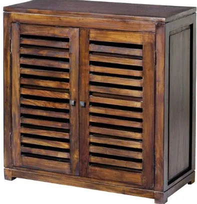
[image:16.612.260.457.345.549.2]1.1 BACKGROUND
Figure 1.1: Example of closed ‘Shoe Rack’
2 technology the invention of this new design of shoe rack is born to be placed on the doors of various household environments, or even hung on small wall spaces. The household problem of putting away shoes is currently solved by various types of furniture, always requiring a certain space, or with designs to be hung to doors, where the main elements for putting away footwear.
This shoe rack basic designed form of a box, but every year the design is constantly changing with more updates design at cheaper price using various materials and can be more easily used, it also does not focus on one form but has variety of aesthetic design and easy assembly. Shoe racks are used to look neat and tidy in every home, office or any place in order to be placed outside and in a place according to their requirements. Hence, all these problems can be solved by putting the shoes carefully at the right place, as well as the problem of dust on shoes and the smell can be addressed using a closed shoe racks.
3 1.2 OBJECTIVE
This project is aimed to study the activities involved in design process for modular product concept for ‘Shoe Rack’ and fabrication of a prototype of the scale 1:2 using sustainable material. The modular product also has to incorporate DIY assembly method. DFMA of a product development and modular design concept also using in this project.
1.3 SCOPE
The scope of studies for this project is to focus on the implementation of modular design concept on close ‘Shoe Rack’ then DFMA method will be apply to the design for developing process. The final product then will be integrated with ‘DIY’ method. After using these three methods, the detailed design concept selected will be developed using software CATIA V5R20.
1.4 PROBLEM STATEMENT
Basically, there are a lot of aspects need to be considered when designing the closed ‘Shoe Rack’. Design of the furniture is essential to ensure that it can easily be adapted for space layout. One major problem that can be seen in the ready-made design configuration of advanced shoe rack can’t be changed with the environment.
5 CHAPTER 2
LITERATURE REVIEW
2.1 INTRODUCTION
This chapter will discuss more about this project using the three concepts. The first topic to be discussed is modular products in embodiment design section. These topics also include definition and the advantages of using these concepts. The second concept will discuss the concept of "Do it yourself’ (DIY) and also the concept of ‘Design for manufacturing and assembly’ (DFMA) for this product design.
6 2.2 ENGINEERING DESIGN PROCESS
Engineering design process has been described as a potential design flow of new products that will suitable the needs of the target user. Product development starts with determining what the requirements that a product must meet the definition of the first and the whole product development process, where the understanding of any problems that occur is essential to achieve the best solution [2].
[image:21.612.129.533.382.653.2]The engineering design process can be used to achieve several different outcomes. However, the emphasis in this project is on product design because it is an area in which many engineers will apply their design skill. The design process is a sequence of events and set of guidelines that helps define a clear starting point that takes the designer a product. There are two sections in design process which is the conceptual design and embodiment design [2].
7 2.2.1 Conceptual Design
Conceptual design is the process by which the design is initiated, carried to the point of creating a number of possible solutions, and narrowed down to a single best concept. Conceptual design is the phase that requires the greatest creativity, involves the most uncertainty, and requires coordination among many function in the business organization. The following are the discrete activities that consider under conceptual design [1].
Furthermore, to be taken in the early stages of product concept to gather information related to the literature is the product itself. Relevant information to perform engineering design is a kind of a lot and come in several forms other than written words. Some examples are coming from the customer surveys and feedback, specifications and drawings for the previous version of the product, and so many resources that are more relevant. By placing the information gathering steps of problem definition and concept generation step, we can find the information required to implement the concept of creative solutions.
2.2.1.1 Concept Generation
This concept generation method is a step in the development of the product as an alternative design concept generated, evaluated, and selected. Terms of design concepts can be defined as an alternative that includes a minimum of principles, the embodiment of abstract and geometric [2].
8 2.2.1.2 Concept Selection
After several concepts have been identified, the best concept will be used in this product. Among the methods used in this project to choose the specification is the Pugh method. This method can choose the product concept based on the criteria and specifications required in a new product [2]. This method is most effective if all the engineering design ideas implemented and agreed compared with only one method.
2.2.1.2.1 Pugh Concept Selection Method
The Pugh method can be performed by the following process: 1. Choose the comparison criteria
2. Select the alternative to be compared 3. Generate score
9
ROW CRITERIA CONCEPT
A B C D
1 CRITERIA A + + +
D
A
T
UM
2 CRITERIA B = - +
3 CRITERIA C - + -
4 CRITERIA D = = =
5 CRITERIA E + = -
6 CRITERIA F - + +
7 CRITERIA G = = =
8 CRITERIA H + + =
9 CRITERIA I - + -
10 CRITERIA J = = +
PLUSES 3 5 4 0
[image:24.612.124.533.91.645.2]MINUSES 3 1 3 0
![Figure 2.1: Engineering Design Process [2]](https://thumb-ap.123doks.com/thumbv2/123dok/569002.67295/21.612.129.533.382.653/figure-engineering-design-process.webp)
![Table 2.1: Example Pugh Method Evaluation Chart [2]](https://thumb-ap.123doks.com/thumbv2/123dok/569002.67295/24.612.124.533.91.645/table-example-pugh-method-evaluation-chart.webp)
