ii
I hereby declare that I have read this thesis and my opinion this thesis is sufficient in term of scope and quality for the award of the bachelor of Mechanical Engineering
(Thermal-Fluid)
iii
I hereby the author, declare this report entitle “EVAPORATIVE ROOF COOLING
SYSTEM USING WATER FOR HOUSEHOLD APPLICATION is my own except
for quotations and summaries which have been duly acknowledgement”
iv
CONTENT
CHAPTER LIST PAGE
DECLARATION ii-iii
ACKNOWLEDGEMENTS xi
ABSTRACT xii
ABSTRAK xiii
LIST OF TABLE vii
LIST OF FIGURE viii
1 INTRODUCTION 1.1 Introduction 1
1.1.2 House Heat Factor 1
1.2 Problem Statement 2
1.3 Objective 4
1.4 Scope 4
1.5 Expected Result 4
2 LITERATURE RIVIEW 2.0 Literature Review 6
2.1 Cooling in House 6
2.2 Roof Evaporative Cooling 8
2.2.1. Roof Evaporative Cooling System 9
v
2.2.1.2 Roof Ponds 10
2.2.1.3 Ponds Beneath the Building 11
2.2.1.4 Moving Water Films 11
2.3 Thermal Comfort 12
2.4 Determine of Thermal Comfort Temperature 13
2.4.1 Environmental Factors 13
2.5.2 Individual Factors 13
2.5.3 Individual Factors 2 14
2.5.3.1 Factors Reducing Clothing Insulation 14
2.5.4 Thermal Comfort Indices and Standards 15
2.5.6 Comfort Standard 17
2.6 Solar Radiation 19
2.7 Climate Effect of Solar Radiation 19
3 METHODOLOGY 3.0 Methodology 20
3.1 Scale Model House 20
3.2 System Principles 22
3.3 System Design 23
3.4 System Operation 23
3.5 The Main Elements for This Evaporative Device 24
3.6 The Advance Element 24
vi
4 RESULTS AND DISCUSSION
4.1 The Laminar Flow 27
4.2 Model of House 28
4.3 Experiment Result 29
4.4 Water Consumption 31
4.5 Temperature Controller 32
5 CONCLUSION AND RECOMMENDATION Conclusion 34
Recommendation For Future Work 34
REFERENCES 36
APPENDIX 37
vii
LIST OF TABLE
BIL TITLE PAGE
1 Table 4.1: The average data form 3 experiments 27
viii
LIST OF FIGURE
BIL TITLE PAGE
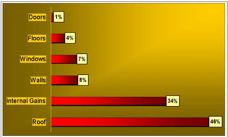
1 Chart of Percentage Heat Transferred at Different 2
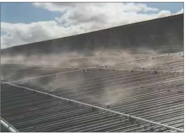
Components of House 2 Evaporative Roof Cooling Using the Sprinkle System 9
3 80% Acceptability Limit for Indoor Operative Temperature based on ASHRAE Adaptive Comfort Model for Naturally 18
Conditioned Spaces 4 Model House Design 21
5 The Principle Evaporative Cooling House 22
6 System Design 23
9 Position 1 25
10 Position 2 25
11 Position 3 26
ix
7 Pipe With Hole and Distance is 2cm is others. 27
8 Two Side of The Hole at The Pipe 27
13 Model of House 26
14 Graph of Temperature against Surface 30
15 Graph of Temperature against Roof Surface 30
16 Temperature Controller Circuit Board 32
x
ACKNOWLEDGEMENT
Firstly, I would like to thanks to Allah S.W.T for his goodness and grace that sustained me to completed Projek Sarjana Muda 1.
Secondly, I take this space opportunity to thanks to my supervisor, Mrs Ainil Jesita Bte Jalaluddin, who has sacrificed his time to monitor my progress in this project and giving me supports and advices regarding my studies in order to become and excellent student. Your advices and moral support will treasure me a lot in my future career.
Next, thank you very much to my lovely parents, Zubir Bin Sadi and Yohanis Bte Abdullah also my family because always motivated me and give me moral supports. Thank you very much for giving me livelong encouragement and inspiration. May Allah bless them
xi
ABSTRACT
xii
ABSTRAK
1
CHAPTER 1
INTRODUCTION
1.1 House Heat Factor
2
1.2 Problem Statement
Heat is transferred to a house via doors, floor, windows, walls, roof etc. The percentage heat transferred through these different components of house is illustrated in figure 1 (source: www.ecoology.com)
[image:13.612.134.520.331.563.2]ASHRAE Model
3
From the graph in figure 1, the roof transfers the highest heat load followed by internal gains such as heat from lighting and computers in house. The combined heat transfer through the walls, doors, windows, and floors is only 20%.
Good house design is very important to prevent heat entering the house. The aspects that must consider are heat gain through roofs, walls, indoor space and floor. If we do not take into account factor, house temperature may reach high and uncomfortable values. For the wall, one of the aspects is the thickness of the wall, if the thickness of the wall is high; the heat allowed into the wall is low compared to wall of lower thickness. Another aspect is the color; colors of the walls must be light or white. If the dark colors are used, the wall will absorb more heat in through the house. For the floor, use tile are better because of smaller heat transfer through the house. If the owner uses a carpet, a slight increases in room temperature maybe observed compared to using tiles only. The amount of space in house also affects in house temperatures. The important aspect is the aspect is the space between the walls and the ceiling. If the space between wall and ceiling small, it is most likely to be hotter than a bigger space between wall and ceiling. (Henry Feriadi et al 2004).
The roof is one of the main contributors to heat gain in a house. Roof materials, structures, colors are different factors affecting heat transfer through a house roof. Another factor is the roof reflectivity. When the roof can reflect the sunlight, its can decrease the heat absorb. In terms of roof structure, the lighter colors are better like white because the heat absorbed is small compared with the darkness colors. Another factor is space between ceiling and roof. Larger space is better than small spaces.
4
energy required to cool the facility. This system will have estimated money payback about 2-3 years.
The temperature of a house is primarily dependent upon the temperature of the roof and walls. Roughly 50% of the heat load in the building is from the roof only. Therefore evaporative roof cooling has been studied for effective cooling. Different systems have been considered in the present study.
1.3 Objective
To design an evaporative roof cooling system using water for household application.
1.4 Scope
- Establish an important parameter in evaporative roof cooling system design. - Conduct experiment by varying the chosen parameter to determine optimum
5
1.5 Expected Result
6
CHAPTER 2
LITERATURE REVIEW
2.1 Cooling in House
There are many methods to reduce heat in a house where it is can be divide in two groups. First method is mechanicals such as air conditioning and exhaust fans. The second method is the passive cooling technique.
Below is the list about of different passive cooling technique for cooling a building (N.M Nahar et al. 2002).
a) Color control
b) thermal insulation over the roof
c) Roof pond/nocturnal cooling and heating d) Evaporative cooling
e) Reflective
f) Air void thermal insulation over the roof (room in space) g) Radiative cooling method
h) Convective cooling method
7
environment inside building. Another study in passive technique has been done by Hamida Ben cheikh et al. (2003). They investigated evaporative-reflective roof for hot dry climates and the analysis of the results shows the most significant factors affecting the cooling power of the passive cooling roof were the water volume, aluminum roof thickness and room air space width.
Ronnen Levinson et al. (2004) investigated cooler tile roofed building with near-infrared-reflective non-white coating. The results are the energy usage is reduced and the return of the money time is about 5-7 years in the warm climates of Fresno and Son Bernardino,
There are many other passive techniques to make the temperature in house constant and at a lower temperature. The passive technique can reduce cost of electricity and this system is environmental friendly. This technique are good for the long term and usually the payback is not too long.
8
2.2 Roof Evaporative Cooling
Evaporative cooling one of the processes are consider the cooling of the air or of thermal masses. It is the natural processes to remove heat from the air. Heat from the air can evaporate the water. The amounts of the heat absorbed to define the evaporated system depend on the amount of the water.
Evaporative cooling system can divided into two processes. This situation can be direct or indirect system depend to the contact the cooled air and the evaporated water. Evaporative system also can be passive or hybrid, based the energy required producing the evaporation.
In the direct situation, the incoming air will contact to the evaporated water and the water to increases the cooled air. For indirect situation, it let the water evaporated at the outside surfaces and the cooling effect to the inlet air like a heat exchanger. The passive evaporative cooling techniques is used of natural evaporation water via out roof surface can be cooled by passive technique like let the water flow at the surface of the roof to make the indoor space cool. The hybrids evaporative techniques is additional the passive technique above with the mechanicals device like pump to generate the water flows as well as the valve to control the flow of the water.
9
2.2.1 Roof Evaporative Cooling System
List of the system in this study
- Roof sprinkler - Roof ponds
- Ponds Beneath the building - Moving water film
2.2.1.1 Roof Sprinkler
10
Figure 2.1: Evaporative roof cooling using the sprinkle system (Source: http://autosftsystem.com)
2.2.1.2 Roof Ponds
11
2.2.1.3 Ponds beneath the Building
Another variant of this physical method is to place ponds on the ground next to buildings, with a much larger depth of water. In this case it is possible to maintain the water temperature near or even below the average diurnal wet bulb temperature by fine spraying of the water over the insulation of the roof. The cold situation can be used. For example the tube is installed inside pond where warmer air of the building circulates during the day. The pond can be defined as a sink of the heat.
2.2.1.4 Moving Water Films
12
2.3 Thermal Comfort
According to America Society of Heating, Refrigerating and air conditioning Engineer (ASHRAE), thermal comfort for human means the satisfaction with the surrounding environment. ASHRAE standard 55 mean thermal environmental conditions for human occupancy. Design Engineers of heating, air ventilation and air conditioning (HVAC) is target to achieve a thermal comfort for most occupants of buildings. Indoor air quality is not target to get the thermal comfort but one of the aspects for HVAC design engineers.
13
2.4 Determine of Thermal Comfort Temperature.
The major aim of comfort research is to find comfort temperature for an individual or group. However, 6 major variables determine how warm or cold a person feels.
2.4.1 Environmental factors
This is 4 factors to show the environment situation
-air temperature -air speed -humidity
-mean radiant temperature
2.4.2 Individual factors
-activity
-clothing insulation