Instabilities in imperfect thick cones subjected to
axial compression and external pressure
O. Ifayefunmi
a, J. B
1
achut
b,*aFaculty of Mechanical Engineering, Universiti Teknikal Malaysia Melaka, Hang Tuah Jaya, 76100 Durian Tunggal, Melaka, Malaysia
bMechanical Engineering, The University of Liverpool, Brownlow Hill, Liverpool L69 3GH, UK
a r t i c l e
i n f o
Article history:
Received 6 February 2013
Received in revised form 5 June 2013 Accepted 29 June 2013
The paper presents results of a numerical study into the buckling resistance of geometrically imperfect mild steel cones subjected to: (a) axial compression only, (b) lateral external pressure only, and (c) axial compression and external pressure acting simultaneously. Initial geometric imperfections are taken in the form of the eigenmode, `a single wave’ extracted from the eigenmode and localized smooth dimple modelled analytically. Load carrying ca-pacity of imperfect models is computed using the Finite Element proprietory code.
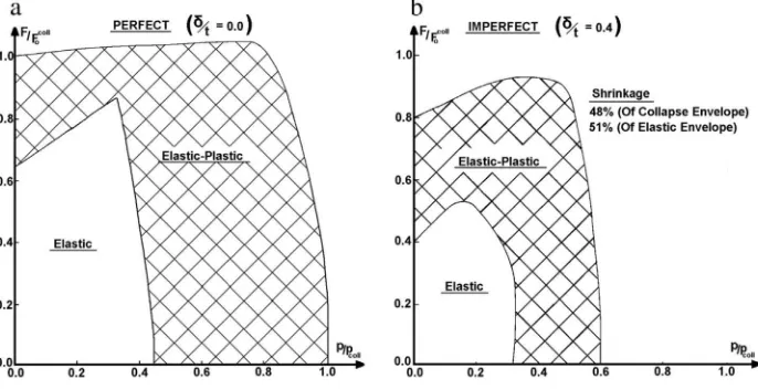
Buckling strength of axially compressed and imperfect cone is only 55% of geometrically perfect model. Buckling strength of a cone subjected to lateral pressure, on the other hand, amounts to 43% of the corresponding value of perfect model. But it is the shrinkage of stability plot of imperfect cone which was found to be significant. For imperfect cones subjected to combined axial compression and external pressure, the collapse envelope shrinks by 48% with the elastic sub-set being reduced by 51%.
Ó2013 Elsevier Ltd. All rights reserved.
1. Introduction
Thick cones are used as structural components in offshore applications, e.g., piles for holding jackets when driven into the sea bed, transition elements between two cylindrical shells of different diameter, and the legs of off-shore drilling rigs. When used as piles for jackets holding, they are, subjected to axial
*Corresponding author.
E-mail address:[email protected](J. B1achut).
Contents lists available atSciVerse ScienceDirect
Marine Structures
j o u r n a l h o m e p a g e : w w w . e l s e v i e r . c o m / l o c a t e / m a r s t r u c
0951-8339/$–see front matterÓ2013 Elsevier Ltd. All rights reserved. http://dx.doi.org/10.1016/j.marstruc.2013.06.004
compression. However, when used as transition components, they are also subjected to external pressure. Hence in the case of off-shore drilling rigs, they are under combined loading. Loss of buckling strength in the elastic–plastic range and the effect of plastic strain at different load levels are of concern at the design stage of these shells.
Details of past studies into sensitivity of buckling load to imperfections in conical shells can be found in Ref.[1]. One of thefirst studies into the sensitivity of the structures critical load to initial geometric imperfections was carried out by Donnell and Wan [2]. The initial post-buckling and imperfection sensitivity of anisotropic conical shells was examined in Refs.[3,4]. A widely used form of shape deviation from perfect geometry, in calculating imperfection sensitivity, is the eigenmode imperfection. Typically, the buckling mode of a perfect shell is superimposed on the perfect shape of shell such as those seen in Refs.[5–7]. In practice, most imperfections found in structures do not have the shape of buckling mode. Refs[8–10]present results of studies of the effect of local imperfection (dimple) on the elastic buckling of axially compressed conical shells. Reference [9] describes an axisymmetric inward bulge introduced into electro-deposited copper wall. Reference[10]on the other hand describes a localized inward dimple introduced during epoxy resin casting. In both cases, the cones were laboratory scale models subjected to buckling test under the application of a single load (axial compression).
It is evident, from literature survey, Ref.[1], that there has been no information on the imperfection sensitivity of conical shells along the combined stability envelope, i.e., for cones subjected to simul-taneous axial compression and external pressure loading, except for Ref.[11]and a recent works by B1achut, Refs[12,13]. Hence a question about the role of initial shape imperfections for the case of cones subjected to combined loading is timely and a valid one.
The current paper presents results of numerical study into the influence of initial shape imperfec-tions on buckling strength of thick truncated steel cones subjected to axial compression only, lateral pressure only and to combined action of axial compression and external pressure acting simultaneously. This study is entirely numerical and it is based on the ABAQUS FE code, Ref.[15]. Frequent references are made to geometry, material properties and test data on mild steel cones provided in Refs.[1,16].
2. Background
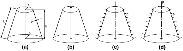
Consider a truncated thick cone with radii,r1 andr2, and uniform wall thickness, t, having the
height,h, slant length,Land semi-vertex angle,
b
, shown inFig. 1a. Assume that the FE models are given byr2/r1¼2.02,r2/t¼34.3,h/r2¼1.01, andb
¼26.56. The above models are subjected to three loadingconditions, shown inFig. 1: (b) axial compression only, (c) lateral external pressure only, and (d) axial compression and external pressure acting simultaneously.
Convergence study was carried outfirst using modified Riks method to determine the number of axial and circumferential elements. Finite Element analysis used eight-node doubly curved shell ele-ments with six degree of freedom (S8R in ABAQUS element library). Results have shown that 142 (axial)40 (hoop) elements were sufficient. In summary, the S8R model had 5680 elements and 17120 nodes.
Fig. 1.Geometry of analysed cones (a) subjected to: (b) axial compression, (c) external pressure, and (d) axial compression and external pressure acting simultaneously.
For axial compression and combined loading cases, cones were clamped at the big end and they were free to move axially at the smaller end, whilst the other degrees of freedom remained constrained (case (i) ofTable 1). For the case of lateral external pressure, cones were clamped at both ends (case (ii) ofTable 1). Cones were assumed to be made from mild steel. The material was modelled as elastic-perfectly plastic withE¼210.49 GPa, the yield point of material,
s
yp¼230.6 MPa, and Poisson’s ratioy
¼0.281 (further details about material properties can be found in Refs.[1,16]).3. Modelling of imperfections
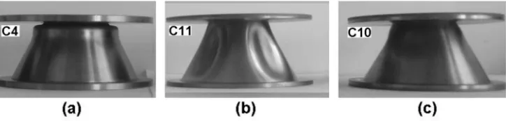
Fig. 2depicts the experimental collapse shape of cones subjected to: (a) axial compression only, (b) lateral external pressure only, and (c) combined action of axial compression and external pressure acting simultaneously (from Ref.[1]).Fig. 3illustrates the sequence in which the load was applied to all tested models (both experimentally and numerically).
It is evident fromFig. 2, that for cones under axial compression only, the collapsed model has an axisymmetric outward bulging in the neighbourhood of the small radius (Fig. 2a). Whereas, for cones subjected to lateral external pressure only, lobes around the hoop are observed in experiments (Fig. 2b). Whilst, for cones subjected to axial compression and external pressure acting simultaneously, it is seen that there is an interaction between the above two forms of failure, i.e., outward bulging close to the small-radius end of the cone and waves around the circumference of the cone (Fig. 2c). Similar behaviour has also been noted in Ref.[12]for steel cones with nominal dimensions given by:r2/t¼54 and
b
¼14.In lieu of the above observations, for design purposes, these failure shapes are considered as initial shape imperfections. Therefore, various combinations of the above modes of failure are modelled as initial geometric imperfections. Next, the buckling strength is to be established usingfinite element code ABAQUS. More specifically these models include: (i) eigenmode imperfections (axial compression – Fig. 4a; lateral pressure - Fig. 4b; axial compression and external pressure acting simultaneously–Fig. 4c), (ii) axisymmetric outward bulge for axially compressed cones–Fig. 5a, (iii) half-wave extracted from eigenmode -Fig. 5b, or localised smooth inward dimple (both forms for external pressure), and (iv) combined axisymmetric outward bulge with single half-wave extracted from the eigenmode -Fig. 5c (the case of combined loading). The half-wave considered here means the inward dimple/portion, only. It is worth noting here that there is no guarantee that these forms of
Table 1
Boundary conditions used:uhdisplacements degree of freedom andvhrotation degree of freedom.
ux uy uz vx vy vz
Fig. 2.Photograph of collapsed cones subjected to axial compression only (C4), lateral external pressure only (C11), and combined loading (C10)–from Ref.[1].
shape deviations from perfect geometry are the worst imperfection profiles–as seen for example in Ref.[13]. The inward and outward dimples with their size, positioning on the slant, and depth were treated as design parameters. Formal structural optimization was used in order tofind the optimum (the largest reduction of buckling strength). Even in this case, there was no guarantee that the global optimum was found, Ref.[13]. Hence imperfection profiles adopted in the current paper should not be seen as the worst possible deviations from perfect geometry.
The following sub-sections describe in detail assumed types of initial shape imperfections and their effect on the load carrying capacity of steel cones.
3.1. Eigenmode imperfections
The analysis of cones with initial geometric imperfections, assumed to be affine to eigenshape, is examined in this sub-section. The number of axial and hoop elements obtained from convergence
Fig. 3.Loading sequence for cones C4, C10 and C11.
studies are used for FE modelling. Elastic buckling analysis was carried outfirst in order to retrieve the eigenmodes. The eigenshape corresponding to the lowest eigenvalue was used in calculations as the imperfection profile. The given mode was superimposed on the perfect geometry with different amplitude of imperfection,
d
. The imperfection amplitude to average wall thickness ratio,d
/tave, wasvaried between 0.0 and 1.0. (wheretave¼2.89 mm and it is the average wall thickness of steel cones
which were tested in Ref.[1]). The modified Riks method was then used to obtain the collapse load. The imperfection sensitivity of the cones along the combined stability domain plot required the following two cases to be analyzedfirst, i.e., (i) cones subjected to axial compression only, and (ii) cones subjected to lateral pressure only. Here, in both cases the amplitude of imperfection has to be the same.
3.2. Smooth inward dimple/outward bulge
One common method of analyzing initial geometric imperfections is the use of shape of the eigenmode, being superimposed on the perfect shape. In the current paper, as mentioned earlier, the eigenshapes were obtained as a result of elastic analysis. This is a customary approach when elastic–
plastic analysis might not return asymmetric bifurcation mode. However this approach may not be realistic, since practically, it is difficult tofind such regular imperfections in real situations. This sub-section examines the effect of initial geometric imperfection modelled as imperfect smooth inward/ outward localized dimple/bulge. The latter profiles might be more realistic from a practical point of view but they still may not be the worst imperfections. For externally pressurized hemispheres/tori-spheres the concept of lower bound envelope successfully utilized an inward dimple with a subsequent experimental verification–see Ref.[14]for details.
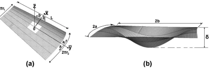
In the current paper a smooth inward dimple shown inFig. 6b is modelled using Eq.(1):
Fig. 5.Axisymmetric outward bulge (a), single half-wave extracted from eigenmode–inward portion (b), and axisymmetric out-ward bulge and single wave extracted from eigenmode (c).
Fig. 6.Position of imperfect area (inward dimplehwhite area)–arrangements for notation (a). View of smooth inward dimple of size: 2a(hoop)2b(slant) (b).
D
z ¼0:25d
where‘a’and‘b’indicate half-span of imperfection in hoop and slant directions, respectively. The maximum inward/outward deflection of the dimple,
D
z, measured in the middle of the dimple is denoted as,d
. This dimple can be located at any position on the cone. The FE grid obtained from con-vergences studies using S8R shell elements was adopted here. The ratio of imperfection amplitude to average wall thickness,d
/tave, was varied between 0.0 and 1.0. The following sections provide resultswhich were obtained for single and combined loading cases using the above types of shape imperfections.
4. Buckling of imperfect cones under axial compression
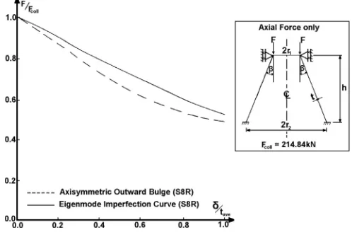
This section examines geometrically imperfect cones subjected to axial compression. The larger radius end of the cone was fully clamped, whereas, at the smaller radius end, only axial, movement was allowed. Two types of initial shape imperfections were considered for axially compressed cones. The
first imperfection corresponds to the eigenmode type deviations obtained using elastic analysis as illustrated inFig. 4a. The next imperfection profile is an axisymmetric outward bulge in the neigh-bourhood of the small end–as illustrated inFig. 5a.
This imperfection shapes were superimposed on the perfect cone with different amplitudes. The effect of imperfection amplitude,
d
, on the collapse load of the cone is shown inFig. 7. It is seen that the magnitude of buckling load for an axisymmetric outward bulge is smaller than the corresponding result obtained for eigenmode shape deviations, i.e.,the outward bulge leads to weaker cones when compared with the eigenshape imperfection. This remains true for the whole range 0.0d
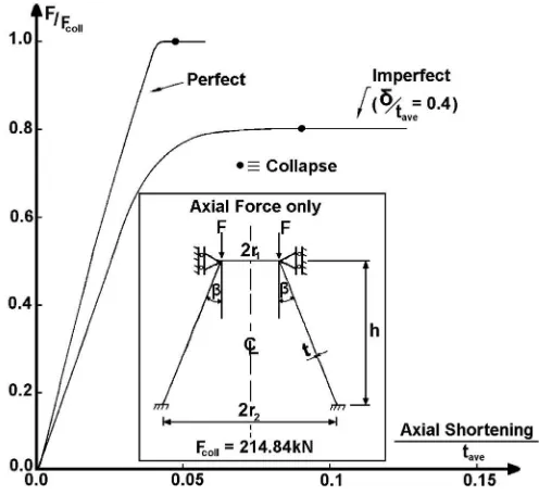
/tave1.0– although the difference is not large.Fig. 8, on the other hand, shows the load deflection curves for: imperfect cone (d
/tave¼0.4, eigenmode), and for a perfect cone. It can be seen that for the imperfect case the collapse load is reduced by 20%. Whereas, atd
/tave¼1, the cones are able to support only 55%,of the load associated with buckling strength of perfect shell. Also, the use of the RIKS method to extract the magnitude of load carrying capacity of imperfect cones is appropriate–as no bifurcation was found between zero load andFcoll.
5. Buckling of imperfect cones under external pressure
In this section, geometrically imperfect cones under external pressure are considered. Both the larger radius end and the smaller radius ends of the cone were fully clamped. Three types of initial
Fig. 7.Sensitivity of the load carrying capacity of axially compressed cones as a function of the imperfection amplitude,d/tave, for eigenmode and axisymmetric outward bulge.
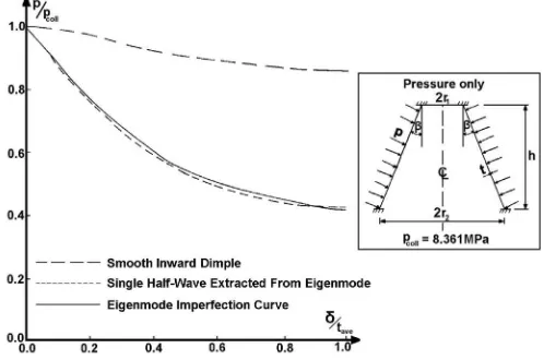
geometric imperfections are considered. Thefirst imperfection corresponds to the eigenmode type shown inFig. 4b. The second imperfection profile is a single half-wave extracted from the eigenmode. Its shape is sketched inFig. 5b. Finally, the third imperfection profile is an inward, localised dimple as given by Eq.(1). This inward local dimple can be located at any position on the cone as illustrated in
Fig. 9. The buckling load of the imperfect cones was then calculated using various combinations of dimple sizes at different locations on the cone slant. Typical results are presented inTable 2. It can be observed, that the load carrying capacity of the cone reduces as the depth of the dimple increases. Also, it can be seen that the location of the dimple has significant influence on the buckling strength of the cone. Locating the dimple at the top end of the cone along the meridian has no effect on the buckling strength, whereas, if the dimple is located at the middle-length, it can reduce the failure load by 14% (
d
/tave¼1.0).Fig. 10depicts the sensitivity for 0.0
d
/tave1.0.The lower two curves inFig. 10indicate that there is practically no difference between results obtained for a single half-wave extracted from the eigenmode and results obtained for full eigenmode shape deviations.
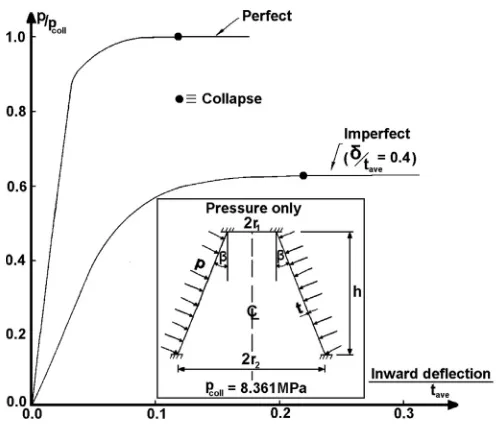
Load deflection curves for imperfect cone (
d
/tave¼0.4) and for a cone with perfect geometry are shown for this case inFig. 11. It can be seen fromFig. 11that for the imperfect cone the bucklingFig. 8.Load deflection curves for: imperfect cone (d/tave¼0.4), and for geometrically perfect cone.
strength amounts to 62% of the perfect case. In the case of
d
/tave¼1, the failure load of the imperfect cone amounts to 43% of the perfect case. Hence when comparing the buckling strength of imperfect shells under axial compression, 55% (Fig. 7), with lateral pressure, 43% (Fig. 10), it is seen that the latter case is more dangerous from a safety point of view.6. Buckling of imperfect cones under combined loading–axial compression and external
pressure
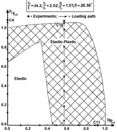
This section examines the influence of initial geometric imperfections for cones subjected to combined loading, i.e., axial compression and external pressure acting simultaneously. Typical com-bined stability envelope for such cones, when geometrically perfect, is shown inFig. 3. Cones are fully clamped at the larger radius end, whereas, at the smaller radius end, only axial movement was allowed. In this section, calculations have been carried out for only one configuration of combined loading: (F/
Fcoll,p/pcoll)h(1.04, 0.58)–related to cone C10 inFig. 3, for example. Details of other configurations can be found in Refs.[1,11]. Computations included: (i) the use of elastic eigenshapes (seeFig. 4c), (ii) the use of imperfection profile being the combination of axisymmetric outward bulge and a single half-wave extracted from the eigenmode (seeFig. 5c). The response curves for imperfect geometries were
Table 2
Imperfection sensitivity of collapse load for cones with smooth inward dimple positioned at various location on the cone meridian.
Location of dimple,y Size of dimple Imperfect collapse pressure (MPa) pimperfectcoll = pcoll
Axial Hoop
2b/L 2a/2pr
L/2–b 0.05 0.05 8.353 1.00
L/2–b 0.25 0.05 7.475 0.89
0 0.05 0.05 8.246 0.99
0 0.05 0.10 8.188 0.98
0 0.05 0.15 8.348 1.00
0 0.05 0.20 8.358 1.00
0 0.25 0.05 7.224 0.86(*)
L/2þb 0.05 0.05 8.354 1.00
L/2þb 0.25 0.05 8.359 1.00
The amplitude of dimples is kept constant for all cases and it equalsd/tave¼1.0 (pcoll¼8.361 MPa; (*)–seeFig. 10)).
Fig. 10.Reduction of the load carrying capacity as a function of the imperfection amplituded/tave. Comparison of sensitivity for eigenmode imperfection, single wave extracted from the eigenmode and for local inward dimple.
computed for the imperfection range 0
d
/tave1.0. The loading path which was adopted is shown in Fig. 3. Imperfect cone was pre-loaded to an initial pressure which was then maintained constant. Next, the magnitude of axial load leading to the collapse was sought through the Riks method. For example, in the case (F/Fcoll,p/pcoll)h(1.04, 0.58), the cone was pre-loaded by external pressure to the levelp/pcoll¼0.58, and this amplitude remained constant whilst the collapse force for the imperfect cone was found to be:F/Fcoll¼0.87 (at
d
/tave¼0.4). The full curve is plotted inFig. 12. As the ratio ofd
/tavein-creases the resulting/computed ratioF/Fcollbecomes smaller and smaller–as seen inFig. 12. It can also
be seen that for the case‘B’the cone could not withstand any load beyond imperfection amplitude,
d
/tave¼0.4 (no converged solution).
Fig. 11. Load deflection curves for: imperfect cone (d/tave¼0.4, S8R), and for perfect cone (SAX2).
Fig. 12.Reduction of the load carrying capacity of cones under combined loading as a function of the imperfection amplituded/tave–
Interactive stability envelope for cone subjected to combined axial compression and external pressure with imperfection amplitude,
d
/tave¼0.4, is plotted inFig. 13. It can be seen that for theimperfect cone with
d
/tave¼0.4, the collapse envelope shrinks by 48% and the elastic envelope shrinks by 51%. Also, the cones subjected to combined loading appear to be more sensitive to shape imper-fections than in the case of either axial compression or external pressure acting alone.7. Conclusions
Although the above results are purely numerical, several conclusions can be drawn for design purposes. It has been seen that the buckling strength of considered cones is affected by all four types of imperfections. Results illustrate complicated nature of cone’s load carrying capacity when the shell is subjected to combined loading.
For axially compressed cones, the eigenmode type shape imperfections are not always the worst initial shape imperfections. Localised, axisymmetric outward bulge can reduce the load carrying ca-pacity marginally more than the corresponding eigenmode type of shape imperfection. It can also be seen that the load carrying capacity of externally pressurized cone is sensitive to different profiles of eigenmode deviations from perfect geometry. It is then immaterial whether the imperfection is in the form of a single half-wave or whether it is affine to the full eigenshape (Fig. 10). The load carrying capacity is not significantly affected by an inward, localised dimple. Equally for the case of combined loading, the eigenshape deviations are not always the worst imperfection (see‘A’inFig. 12and note that the eigenshape was extracted as a result of elastic analysis, only).
The case of combined axisymmetric outward bulge and a single half-wave extracted from the eigenmode proved to be more dangerous for design purposes. It is therefore, important to assess the buckling strength not only through a single eigenmode type imperfection profile but also by allowing other initial shape imperfections such as localized inward dimple/axisymmetric outward bulge and possibly by allowing modal interaction.
Finally, these numerical results are based on the FE calculations and it would be desirable to benchmark them against experimental data.
References
[1] Ifayefunmi O. Combined stability of conical shells. PhD thesis. Liverpool, U.K: The University of Liverpool; 2011. [2] Donnell LH, Wan CC. Effects of imperfections on buckling of thin cylinders and columns under axial compression. Journal
of Applied Mechanics 1950;17(1):73–83.
[3] Zhang GQ, Arbocz J. Initial postbuckling analysis of anisotropic conical shells. In: Proceedings of 34th AIAA/ASME/ASCE/ AHS/ASC Structures, Structural Dynamics and Materials Conference, USA 19–22 April, 1993. p. 326–35.
[4] Zhang GQ. Stability analysis of anisotropic conical shells. PhD Dissertation. Delft University of Technology; 1993. [5] Chryssanthopoulos MK, Poggi C, Spagnoli A. Buckling design of conical shells based on validated numerical models.
Thin-Walled Structures 1998;31(1–3):257–70.
[6] Jabareen M, Sheinman I. Postbuckling analysis of geometrically imperfect conical shells. ASCE Journal of Engineering Mechanics 2006;132(12):1326–34.
[7] Jabareen M, Sheinman I. Stability of imperfect stiffened conical shells. International Journal of Solids and Structures 2009; 46(10):2111–25.
[8] Cooper PA, Dexter CB. Buckling of a conical shell with local imperfections. NASA TM X-2991; 1974. p. 1–21. [9] Arbocz J. Buckling of conical shells under axial compression. NASA CR-1162; 1968. p. 1–52.
[10] Foster CG. Axial compression buckling of conical and cylindrical shells. Experimental Mechanics 1987;27(3):255–61. [11] Ifayefunmi O, B1achut J. The effect of shape, boundary and thickness imperfections on plastic buckling of cones. In:
Pro-ceedings of the ASME 2011 30th international conference on ocean, offshore and arctic engineering (OMAE 2011), vol. 2. NY, USA: ASME; 2011, ISBN 978-0-7918-4434-2; 2011. p. 23–33. OMAE2011-49055.
[12] B1achut J. Interactive plastic buckling of cones subjected to axial compression and external pressure. Ocean Engineering 2012;48(7):10–6.
[13] B1achut J. Combined stability of geometrically imperfect conical shells. Thin-Walled Structures 2013;67:121–8. [14] B1achut J, Magnucki K. Strength, stability and optimization of pressure vessels: review of selected problems. Applied
Mechanics Reviews, Transactions of the ASME 2008;61(6):060801-1–060801–060833.
[15] Hibbitt, Karlsson, Sorensen. ABAQUS-theory and standard user’s manual. Version 6.4, USA, Pawtucket; 2006.
[16] B1achut J, Ifayefunmi O. Plastic buckling of conical shells. Journal of Offshore Mechanics and Arctic Engineering, Trans-actions of the ASME 2010;132(4):041401-1–041401-11.