ii
UNIVERSITI TEKNIKAL MALAYSIA MELAKA
High Performance Laser Drilling on
Stainless Steel
This report is submitted in accordance with the partial requirement of the
Universiti Teknikal Malaysia Melaka for the Bachelor of Manufacturing Engineering (Manufacturing Process and System)
By:
Khoo Mun Choon
Faculty of Manufacturing Engineering
iii
SESI PENGAJIAN : _______________________
Saya _____________________________________________________________________
mengaku membenarkan t esis (PSM Sarj ana) ini disimpan di Perpust akaan Universit i Teknikal Malaysia Melaka (UTeM) dengan syarat -syarat kegunaan sepert i berikut :
1. Tesis adalah hak milik Universit i Teknikal Malaysia Melaka .
2. Perpust akaan Universit i Teknikal Malaysia Melaka dibenarkan membuat salinan unt uk t uj uan pengaj ian sahaj a.
3. Perpust akaan dibenarkan membuat salinan t esis ini sebagai bahan pert ukaran ant ara inst it usi pengaj ian t inggi.
(Mengandungi maklumat yang berdarj ah keselamat an at au kepent ingan Mal aysia yang t ermakt ub di dalam AKTA RAHSIA RASMI 1972)
(Mengandungi maklumat TERHAD yang t elah dit ent ukan oleh organisasi/ badan di mana penyelidikan dij alankan)
(TANDATANGAN PENULIS)
iv
DECLARATION
I hereby declare that this report entitled
HIGH PERFORMANCE LASER DRILLING ON STAINLESS STEEL is the result of my own research except as cited in the references.
Signature :
Author’s Name : KHOO MUN CHOON
v
APPROVAL
This report is submitted to the Faculty of Manufacturing Engineering of UTeM as a partial fulfillment of the requirements for the degree of Bachelor
of Manufacturing Engineering (Manufacturing Process and System ). The
member of the supervisory committee is as follow:
Dr. Bagas Wardono
vi
ABSTRACT
LASER stands for Light Amplification by Stimulated Emission of Radiation. Drilling is one of the most important and successful applications of industrial lasers. Laser drilling of metals is used to produce tiny orifices in the workpiece by removing material to create through holes. However in this study, the focus was on the high performance laser drilling by removing a certain amount of workpiece by conducting trepanning process on stainless steel. In this laser drilling process, the quality of drilled holes was evaluated. A thorough study of the process variables on the quality of the holes produced was performed. In present study, the laser parametric effects and the machining characteristic of surface roughness, Ra on the hole quality after the
drilling process run are examined. A statistical approach, referred to as factorial design, given a value of significant level, alpha = 0.05 (95% confidence level) is used to test the parameters combinations that affect the hole quality and surface characteristic. For this experimental study, a two level full factorial design were used to examine the influence of parameters combinations on hole quality. The surface roughness is evaluated by measuring the value of Ra on top and bottom side of
vii
ABSTRAK
LASER ditakrifkan sebagai Light Amplification by Stimulated Emission of Radiation.
Penggerudian merupakan suatu proses yang amat penting dan selalu diaplikasikan dalam industri laser. Penggerudian laser ke atas bahan besi merupakan proses menghasilkan lubang kecil yang tembus terhadap bahan kerja dengan membuang sebahagian daripada bahan besi tersebut. Akan tetapi, di dalam kertas kerja ini, penumpuan akan diberikan kepada keberkesanan penggerudian laser dengan mengunakan cara ‘trepanning’ proses ke atas stainless steel. Dalam kajian ini, kualiti lubang-lubang yang dihasilkan akan dinilai. Ciri pemesinan seperti kekasaran permukaan, Ra pada lubang selepas proses penggerudian turut dikaji. Satu kajian
mendalam akan dijalankan terhadap parameter-parameter yang menghasilkan lubang-lubang tersebut dengan pedekatan statistic menggunakan two-level factorial
design. Nilai alpha = 0.05 (95% confidence level) digunakan bagi menguji
viii
ACKNOWLEDGEMENTS
First and foremost, I would like to express my sincere gratitude and appreciation to my supervisor Dr. Bagas Wardono for giving me this opportunity to take part in this experimental study. I am deeply grateful to his guidance during the course of the final year’s project whereby his advice and encouragement played an important and major role for the success of this final year project.
I would also like to thank the Faculty of Manufacturing Engineering of Universiti Teknikal Malaysia Melaka, by providing the necessary facilities, equipments, materials and support. Besides that, I would like to acknowledge the assistance, cooperation and support of the lab assistants in various section such as En. Jaafar, En. Nazri, En. Helmi, and etc.
Furthermore, I would like to thank my precious friends and my fellow course mates for their support; they include Chan Wai Pin, Ashraf and Nabil from Manufacturing Design course, and many more.
ix
List of Abbreviations, Symbols, Nomenclatures……….xv
1. INTRODUCTION……….……….1
1.1 Background………1
1.2 Problem Statements………1
1.3 Objectives and Aims of Study……….4
1.4 Scope of Study……….4
2. LITERATURE REVIEW……….5
2.1 Fundamental Principle of Laser………...………5
2.2 Laser Drilling………..…….8
2.3 Types of Laser………...…….10
2.3.1 Nd: YAG……….……11
2.3.2 Carbon Dioxide, CO2………..13
2.4 Machine and Material Review………..15
x
2.5.4 Focal Height………20
2.6 Machining Characteristics……….21
2.6.1 Surface Roughness………..……21
2.6.2 Surface Hardness………22
2.7 Past Studies………22
3. PROCEDURES/METHODOLOGY………..…..29
3.1 Introduction on Design of Experiment………...29
3.2 Full Factorial Design………...31
3.2.1 Define objective………..34
3.2.2 Identify design factors and level……….…34
3.2.3 Identify response variables……….35
3.2.4 Preparation of experiment………..….35
3.2.5 Performing experiment trial and actual run………...….38
3.2.6 Analyzed and interpret results from experiment run……….43
3.3 Project Flow Chart………..44
4. RESULT AND DISCUSSION………...………46
4.1 Qualitative Analysis on hole appearance………46
4.2 Qualitative Analysis on surface roughness……….…48
4.3 Quantitative Analysis on surface roughness………..…….50
4.4 Qualitative Analysis on burr width……….59
4.5 Quantitative Analysis on burr width………..………….62
5. CONCLUSION AND SUGGESTION………...…….69
REFERENCE………...………...71
APPENDICES………...……….75
A Data collection for surface roughness measurement………..75
B Data collection for burr width measurement………76
C ANOVA for mean surface roughness……….77
xi
LIST OF FIGURES
1.1 Variation of entrance geometry of laser percussion drilled holes 2
1.2 Laser texturing of engine cylinder walls 3
2.1 Initial phase of heat-flow in laser processing 6 2.2 Intermediate phase of heat-flow in laser processing 7 2.3 Emission phase of heat-flow in laser processing 7
2.4 Setup of a simple optically pumped laser 7
2.5 The laser drilling operation 8
2.6 Basic Diagram of Laser Cutting Operation 9
2.7 150 micron diameter hole in silicon 9
2.8 Diagram of surface characteristic 21
2.9 Picture of a UV laser drilled hole on copper 26
2.10 A laser cutting system machine 26
2.11 Laser Trepanning 27
2.12 Single-shot drilling (left) and percussion drilling (right) 27
3.1 Two factors and three factors design 32
3.2 A central composite design with two factors 33
3.3 Stainless steel material 35
3.4 HELIUS 2513 CO2 laser machine 36
3.5 The laser machine cutting panel containing cutting nozzle and cutting lens
37
3.6 Cutting nozzle with different sizes of diameter 37 3.7 The three specimens’ material cut using laser machine 38 3.8 The product produced from the laser cutting process 38
3.9 Cutting process with power bend saw 39
3.10 Stainless steel ‘fishbone’ specimen 39
xii
3.12 Display of surface roughness measurement 40 3.13 The probe is measuring along the movement path 41 3.14 Surface roughness measurement on other surface of holes 41 3.15 Stainless steel specimen for microscopic view 42
3.16 Zeiss Microscope Axioskop Two Mat 43
3.17 Project Flow Chart 44
4.1.1 The back side view of the specimen 46
4.1.2 Side and slanting top view of the specimen plate 47
4.1.3 One of the defects of laser cutting 47
4.1.4 The by-product of laser cutting machine 47
4.2.1 Microscopic view 5X of specimen 3 experiment run no.7 and no.13 48 4.2.2 Microscopic view 5X of specimen 3 experiment run no.16 and no.20 49 4.2.3 Microscopic view 5X of specimen 3 experiment run no.2 and no.15 49 4.2.4 Microscopic view 5X of specimen 3 experiment run no.6 and no.21 49
4.3.1 Normal probability effects plot for surface roughness 51 4.3.2 Pareto Chart of effects for surface roughness 52
4.3.3 Residual plots for surface roughness 53
4.3.4 Main Effects Plot (data means) for surface roughness 54 4.3.5 Interaction Plot (data means) for surface roughness 55
4.3.6 Surface Plot of surface roughness 57
4.3.7 Contour Plot of surface roughness 58
xiii
4.4.8 Microscopic view 5X for experiment run no 6, 11, and 12 61 4.4.9 Microscopic view 5X for experiment run no 9, 14, and 21 61
4.5.1 Normal probability effects plot for burr width 62 4.5.2 Pareto Chart of effects for burr width 63
4.5.3 Residual plot for burr width 63
4.5.4 Main Effects Plot (data means) for burr width 64 4.5.5 Interaction Plot (data means) for burr width 65
4.5.6 Surface Plot of burr width 67
xiv
LIST OF TABLES
2.1 Some properties of Nd: YAG laser 12
2.2 Typical Carbon Dioxide Laser Parameter 14
2.3 Composition ranges for 304 stainless steels 17 2.4 Mechanical properties of 304 stainless steels 17 2.5 Typical physical properties for 304 grade stainless steels 18 2.6 Grade specifications for 304 stainless steels 18 2.7 Comparison of typical performance data of industrial lasers 24 2.8 Comparison of EDM drilling, laser drilling and mechanical drilling 25
3.1 Fixed variables used for the experiment 34 3.2 Variables and levels selected for the experiment 34
xv
LIST OF ABBREVIATIONS, SYMBOLS,
NOMENCLATURES
ANOVA - Analysis of Variance
ANSI - American National Standards Institute ASTM - American Society for Testing and Materials
cw - Continuous wave
DOE - Design of experiment
EDM - Electrical discharge machining HAZ - Heat affected Zone
LASER - Light Amplification by Stimulated Emission of Radiation LMP - Laser Machining Process
Nd - Neodymium doped
PSA - Pressure swing absorption TEM - Transmission electron microscopy
UV - Ultraviolet
1
CHAPTER 1
INTRODUCTION
1.1 Background of Study
Laser machining means material removal accomplished by laser material interaction, generally speaking, these processes include drilling, cutting, grooving, and marking or scribing. Before we proceed into the details of laser machining processes (LMP), we need to know what are the features of LMP and when do we choose LMP instead of tradition machining processes [3].
Laser machining processes transport photon energy into target material in the form of thermal energy or photochemical energy; they remove material by melting and blow away, or by direct vaporization/ablation. On the other hand, traditional machining processes rely on mechanical stresses induced by tools to break the bonds of materials. This basic difference in material removal mechanism decides the advantages and disadvantages of LMP compared with traditional machining processes [3].
1.2 Problem Statements
2
Yilbas [1], stresses out for the application of laser beam used in micromachining, various factors must be considered and evaluated. These factors include the laser pulse length, the pulse energy, the focus settings of the focusing lens, and the work piece thickness and thermal properties. Effective utilization of the laser depends very much upon the proper selection and optimization of these factors. Limited information on how these factors affect the laser-drilled hole quality have seriously hindered the growth of laser applications in micromachining, because the effects of some of these factors have been underestimated previously. Therefore, a systematic study to establish and recognize the machining standards to produce holes with good quality is necessary.
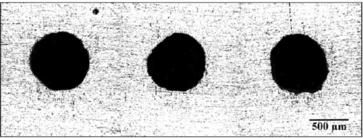
There are various research objectives that have been performed by researchers in the past. One of them is the repeatability of laser producing holes. The fact shows that it is often difficult to produce repeatable holes with laser percussion drilling. This makes the process of fabricating holes with desired hole geometry to the industrial tolerances difficult to achieve. Figure 1.1 illustrates a set of three holes drilled with the same laser parameters and yet the hole geometry is different from one hole to another. In view of this, it becomes necessary to understand the characteristics of repeatability [2].
Figure 1.1: Variation of entrance geometry of laser percussion drilled holes
3
Other topics involving LMP include cutting, grooving, and marking or scribing. In laser cutting, laser can separate workpieces along lines or curves, such processes are called laser cutting processes. Thin workpieces may be difficult to cut by other means, while laser cutting is suitable because of it noncontact feature. Lasers have been used to cut a wide range of materials. CO2 laser and Nd:YAG laser
are the most popular laser in cutting, they can provide high powers (above 1 kW) for high speed cutting. Ultraviolet (UV) lasers are widely used for thin layer cuttings or organic material cutting. Gas jet is often used to improve the cutting efficiency. Laser marking, scribing and texturing refer to laser machining of material surfaces, usually a very shallow layer of material is ablated or melted and a mark or pattern is formed. Laser grooving is similar to laser cutting except that grooving does not cut through the material [3].
Figure 1.2: Laser texturing of engine cylinder walls [3].
4
1.3 Objectives and Aims of Study
1) To gain basic knowledge on advanced machining using laser system. 2) To learn the basic principles on the laser operating system.
3) To identify the parameters used in laser drilling process.
4) To determine the basic machining characteristics such as surface roughness.
5) To apply statistical analysis such as design of experiment (DOE) using suitable design method to select the optimal machining conditions for good hole quality.
1.4 Scopes of Study
5
CHAPTER 2
LITERATURE REVIEW
2.1 Fundamental Principle of Laser
The word laser is an acronym for Light Amplification by Stimulated Emission of Radiation. A laser device is a light source that amplifies light and produces a highly directional, high-intensity beam that most often has a very pure frequency or wavelength. It comes in sizes ranging from approximately one tenth the diameter of a human hair to the size of a very large building, in powers ranging from 10-9 to 1020 W, and in wavelengths ranging from microwave to the soft-X-ray spectral regions with corresponding frequencies from 1011 to 1017 Hz. Laser have pulse energies as high as 104 J and pulse durations as short as 5 x 10-15 s. The beam of light generated by a typical laser can have many properties that are unique. When comparing laser properties to those of other light sources, it can be readily recognized that the values of various parameters for laser light either greatly exceed or are much more restrictive than the values for many common light sources. “A laser is a specialized light source that should be used only when its unique properties are required” [4].
The starting process in laser materials processing is always the absorption of a raw or focused laser beam at surface of the workpiece. The beam is usually incident normal to the surface of the workpiece. This absorption is determined by the absorptivity and reflectivity of the material. Metals, for example, absorb an increasing fraction of the beam power as the wavelength decreases from the 10.6µm of CO2 lasers to 1.06µm of Nd:YAG lasers and to the 0.8-1.0µm of diode lasers. For
6
taken can give a direct measure of how efficiently laser power can be used. In this case the shorter wavelength lasers are preferable due to their higher absorptivity.
The second stage of laser material processing is the transfer of heat into the workpiece by conduction. This is illustrated in Figure 2.1. In the initial phase the heat-flow is nearly one dimensional into the depth of the workpiece. Lateral heat conduction, which can be viewed as a loss mechanism, is negligible. However, at longer period, the isotherms turn into three dimensional forms. The absorption zone can then be thought of as a point source with large lateral heat conduction losses. The lager the spot size and the smaller the thermal diffusivity, the longer the process can be regarded as being in the one dimensional case [9].
Atoms and molecules have determinate energetic levels, which can be low or high. The low energetic levels can be excited at high levels, generally by heating. Once they reach the energetic superior levels, they go back to the original state, and they return energy in a light form.
Figure 2.1: Initial phase [9].
Under normal conditions, the atoms proportion in low energetic levels in a body is bigger than that of the atoms that are found in superior levels, by this reason, any luminous beam that crosses a body loses energy, since part of its photons are absorbed when crossing.
7
radiation that is in phase with the wavelength that has stimulated it as shown in Figure 2.2.
Figure 2.2: Intermediate phase [9].
The new emission increase, that is to say, amplifies the wave. If the phenomenon can be multiplied, we arrive to the fact that the percentage of atoms with high energy levels will be superior to the percentage of atoms in normal state. This phenomenon is known as population inversion shown in Figure 2.3.
Figure 2.3: Emission phase [9].
Then, the resulting beam is a coherent light beam and it can be high-powered. The possibility of stimulating the radiation was already anticipated by A. Einstein in 1917, but the devices to build them were not created till the 1950s [9]. Figure 2.4 below shows the simple setup of an optical pumped laser.
8
2.2 Laser Drilling
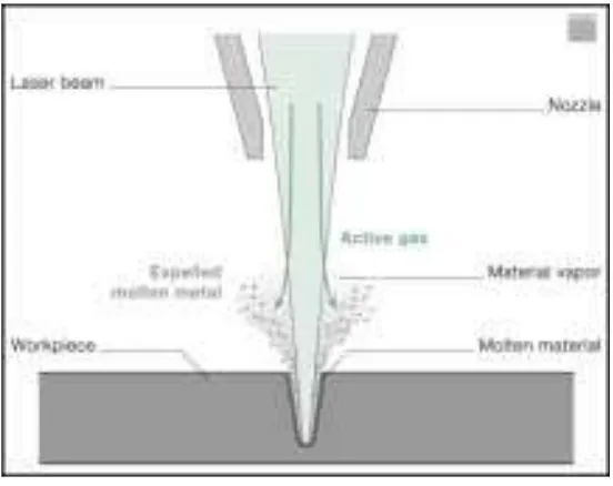
In laser drilling, a short laser pulse with high power density feeds energy into the workpiece extremely quickly, causing the material to melt and vaporize. The greater the pulse energy is the more material is melted and vaporized. Vaporization causes the material volume in the drilled hole to increase suddenly, creating high pressure. The vapour pressure expels the molten material from the hole. Spatter and vapour shoot upward in the direction of the processing optics. Once the laser beam breaks through to the other side, the spatter and vapour exit through the bottom. To prevent damage to the processing optics, manufacturers design the machines so that there is a large distance between the optics and the workpiece. A coaxial gas flow can also be used to shield the optics from spatter [10].
Figure 2.5: The laser drilling operation; the laser melts and vaporizes the material.
9
Figure 2.6: Basic Diagram of Laser Cutting Operation [7]
10
2.3 Types of Laser
Common types of lasers are [11]:
• Semiconductor lasers (mostly laser diodes), electrically (or sometimes optically) pumped, efficiently generating very high output powers (but typically with poor beam quality), or small powers with good spatial properties (e.g. for application in CD and DVD players), or pulses (e.g. for telecom applications) with very high pulse repetition rates.
• Solid state lasers based on ion-doped crystals or glasses, pumped with discharge lamps or laser diodes, generating high output powers, or lower powers with very high beam quality, spectral purity, and/or stability (e.g. for measurement purposes), or ultrashort pulses with picoseconds or femtosecond durations. Common gain media are Nd:YAG, Nd:glass, Yb:YAG, Yb:glass, Er:Yb:glass, Ti:sapphire, Cr:YAG, Cr:LiSAF, and Cr:LiCaF.
• Fiber lasers, based on optical glass fibers which are doped with some laser-active ions in the fiber core. Fiber lasers can achieve extremely high output powers (up to kilowatts) with good beam quality, allow for widely wavelength-tunable operation, narrow line width operation, etc.
• Gas lasers (e.g. helium-neon lasers, CO2 lasers, and argon ion lasers) and
excimer lasers, based on gases which are typically excited with electrical discharges. Frequently used gases include CO2, argon, krypton, and gas
mixtures such as helium/neon. Common excimers are ArF, KrF, XeF, and F2.
![Figure 1.2: Laser texturing of engine cylinder walls [3].](https://thumb-ap.123doks.com/thumbv2/123dok/653387.79739/17.595.168.440.352.514/figure-laser-texturing-engine-cylinder-walls.webp)
![Figure 2.1: Initial phase [9].](https://thumb-ap.123doks.com/thumbv2/123dok/653387.79739/20.595.159.454.436.494/figure-initial-phase.webp)
![Figure 2.4: Setup of a simple optically pumped laser [9].](https://thumb-ap.123doks.com/thumbv2/123dok/653387.79739/21.595.137.472.627.711/figure-setup-simple-optically-pumped-laser.webp)
![Figure 2.7: 150 micron diameter hole in silicon [16]](https://thumb-ap.123doks.com/thumbv2/123dok/653387.79739/23.595.165.446.81.393/figure-micron-diameter-hole-in-silicon.webp)
