APPROVAL
“I hereby declare that I have read this thesis and in my opinion this thesis is sufficient in term of scope and quality for the award of degree of Bachelor
Mechanical Engineering (Thermal-Fluids)”
Signature : ……….
Supervisor’s Name : ……….
THE STUDY OF FLOW VISUALIZATION ON LNT CATALYTIC CONVERTER USING CFD-FLUENT
GOH WERN CHIE
This report is submitted as partial requirement for the completion of the award of Bachelor of Mechanical Engineering (Thermal Fluids) Degree Programme
The Faculty of Mechanical Engineering Universiti Teknikal Malaysia Melaka
ii
DECLARATION
“I hereby, declare this thesis is result of my own research except as cited in the references”
Signature : ………
Author’s Name : Goh Wern Chie
iii
ACKNOWLEDGEMENT
First and foremost, I would like to convey my sincere thank you to my supervisor-En. Shafizal bin Mat, who is willing to offer his support throughout my final year project; He has graciously contributed his time, patience, and guidance in helping me completing my project. His experience in this related topic has also given me a boost of confidence in conducting my experimental work. Not to forget, I would also like to thank him for re-checking my report writing thoroughly and frequently.
Also, I would like to send my greatest gratitude to En. Mohd Afzanizam bin Mohd Rosli, who has helped me so much in my simulation work. Without him, I would never achieve what I have meant to complete. He has never given up on me when I doubt myself in completing this project. His constant encouragement and guidance had brought me to the final stage of my project.
iv
I would also like to express a special thank you to En. Safarudin Gazali Herawan and En. Mohd Haizal bin Mohd Husin who has unselfishly sharing their wisdom. They had willingly sacrifices their time and patience in providing me with sufficient information and advice regarding my project.
A special thanks also to En. Ahmad Kamal bin Mat Yamin. He has been so helpful and concern over my project, especially during the semester break in December 2007. Besides providing me with a few alternatives and ideas to my project, he also taught me to be persistent in pursuing my goal. He asked me good questions and always keeps me alert on my weakness in this project.
Besides my advisors, I would also like to thank UTeM lab technicians En. Asjufri bin Muhajir, En. Ismail bin Ibrahim and En. Mohd Rizal bin Rosli for their assistance and guidance. Thank you also to UTeM librarians and staffs for their assistance and provision of information regarding UTeM’s facilities and resources.
v
ABSTRAK
vi
ABSTRACT
vii
TABLE OF CONTENTS
CHAPTER TOPIC PAGE
DECLARATION ii
AKNOWLEDGEMENT iii
ABSTRACT v
TABLE OF CONTENTS vii
LIST OF FIGURES x
LIST OF TABLES xi
NOMENCLATURE xii
LIST OF APPENDICES xiii
1.0 INTRODUCTION 1
1.1 Background Study 1
1.2 Problem Statement 3
1.3 Project Objectives 3
1.4 Project Scope 4
1.5 Project Outline 5
2.0 LITERATURE REVIEW 6
2.1 Fundamental of Internal Combustion Engine 6
2.2 Exhaust System 7
viii
2.3.1 NOx Formation in Diesel Engine 10
2.3.2 NOx Environment and Health Effects 12
2.3.3 NOx Emission Control 13
2.4 Automotive Catalytic Converter 14
2.4.1 Diesel Automotive Catalytic Converter 17
2.4.2 NOx Control Catalytic Converter 18
2.4.2.1 Selective Catalytic Reduction (SCR) 19
2.4.2.2 Three-way Catalytic Converter (TWC) 20
2.4.2.3 Lean NOx Trap Catalyst (LNT) 21
2.5 Computational Fluid Dynamics 23
2.5.1 Laminar Flow and Turbulent Flow 24
2.6 Research Summary 25
3.0 METHODOLOGY 28
3.1 Introduction 28
3.2 Model Preparation 28
3.2.1 Model Reference Data 29
3.2.2 Mesh Modeling in CFD-GAMBIT 29
3.3 Flow Analysis in CFD-FLUENT 34
3.4 Methodology Flowchart 39
4.0 RESULTS AND DISCUSSION 40
4.1 CFD Result 40
4.1.1 Path-line Visualization 40
ix
4.1.3 Pressure Profile 46
5.0 CONCLUSION AND RECOMMENDATIONS 48
5.1 Conclusions 48
5.2 Recommendation 49
REFERENCES 50
x
LIST OF FIGURES
NO TITLE PAGE
Figure 1 The typical exhaust system on a commercial car 7 Figure 2 The EURO NOx and PM Standard for Diesel cars 13 Figure 3 Various types of Monolithic materials 15 Figure 4 The combination of LNT and other Catalytic Converter 21
Figure 5 Schematic of NOx reduction mechanism 22
Figure 6 Temperature Contour and Streamline of Flow visualization of a catalytic converter during cold start of the engine 24 Figure 7 Schematic of the catalytic converter considered in
respective studies 25
Figure 8 Location of coordinates on a 2D Catalytic converter model 30
Figure 9 Methodology Flow Chart 39
Figure 10 Path-line flow visualization 41
Figure 11 The enlarged part of the vortex area 41
Figure 12 Vector plot in the diffuser upstream at the monolith inlet section 42 Figure 13 The contours of Velocity Magnitude of the LNT model 44 Figure 14 The path-line velocity magnitude pattern 44
Figure 15 The Profiles of Total Pressure. 46
xi
LIST OF TABLES
NO TITLE PAGE
Table 1 The breakdown of the Automotive Exhaust System 8 Table 2 Exhaust composition and exhaust gas temperature of
different engine type 10
Table 3 The beaded catalyst and honeycomb catalyst 16 Table 4 The DOC and DPF used in diesel automotive exhaust system 17 Table 5 Pressure drop and Gamma Factor values obtained
by CFD and FRM 27
Table 6 Geometrical data for the catalytic converter 29 Table 7 Step-by-step CFD-GAMBIT modeling of 2D LNT
catalytic Converter 30
xii
NOMENCLATURE
Al2O3 Alumina
BaO Barium Oxide
CaO Calcium Oxide
CARB California Air Resource Board
CO Corbon Monoxide
CO2 Corbon Dioxide
DOC Diesel Oxidation Catalyst DPF Diesel Particulate Filter
EPA Environment Protection Agency EURO / EU European Union
HC Hydrocarbon
IC Internal Combustion
LNT Lean NOx Trap
N2 Nitrogen gas
N2O Dinitrogen Monoxide
N2O3 Dinitrogen Trioxide
N2O4 Dinitrogen Trioxide
N2O5 Dinitrogen Pentroxide
Na2O Sodium Oxide
NO Nitric Oxide
NO2 Nitrogen Dioxide
NOx Nitrogen Oxide
NSR NOx Storage Reduction Catalyst
PM Particulate Matter
xiii
LIST OF APPENDICES
TITLE APPENDIX
CHAPTER 1
INTRODUCTION
1.1 Background Study
The need for more energy in developing countries has substantially contributes to severe environmental pollutions. Increasing demands for long range transportation are one of the responsible facts that contribute to such problem. Vehicles with either gasoline engine or diesel engine, burn fuel to generate power, which eventually release harmful substances such as Carbon Monoxide (CO); Hydrocarbons (HC); Particulate Matter (PM) or soot; and Nitrogen Oxides (NOx). These substances do not only pollute the air, but they are also one of the main factors in causing adverse human health.
2
When the available three-way-catalyst (TWC) was proven to be ineffective for NOx removal, new approaches for NOx reduction in lean-burned diesel engine are considered. By early 2006, the lean NOx trap (LNT) catalyst seems to be the most promising NOx reduction technology under consideration. Discovered by Toyota in the mid 90s’, the lean NOx trap catalyst consists of earth alkaline oxides on wide surface area base material, which has the ability to store NOx under lean condition and release it as harmless substances during rich engine condition. At January 8th, 2007, the Volkswagen Media Services has made a prediction of releasing
the LNT catalyst on its VW Jetta Clean TDi and VW Tiguan concept vehicles. The models are planned to be released into the America market as part of the “BlueTec” program from Audi, Daimler-Chrysler and Volkswagen.
Apart from the effectiveness of the LNT catalyst in reducing harmful substances from the exhaust emission, the flow distribution within the catalytic converter plays an equally important role in determining both the performance of the catalytic converter, as well as the engine performance. The effects of the flow pattern through the 3 main parts of the catalytic converter-the inlet diffuser, the monolithic structure and the outlet nozzle, strictly determine the performance of the exhaust system. The illustration of the flow distribution through the catalytic converter is performed in this study to aid the understanding of the LNT catalytic converter design against the exhaust flow regarding the flow velocity, temperature, pressure, and flow rate. CFD-FLUENT software is used in this study to perform the flow distribution analysis.
3
1.2 Problem Statement
The combination of diesel engine’s refinement, drivability, and fuel economy has entitled it the preference engine in Europe. Ironically, diesel engine produces more NOx than gasoline engine. As focuses were on the effectiveness of the LNT in NOx removal, another arise issue that rarely appeal to the public is the flow pattern within the catalytic converter. Abide from the LNT performance base on its chemical reactions against the exhaust emission; studies were performed to analyze the flow pattern through the diffuser, monolithic structure and the nozzle of the catalytic converter. In completing this study, it is expected to obtain answers for the following open ended questions;
What is the corresponding flow pattern at the specified parts of the LNT catalytic converter?
What relation can be built up between the flow distributions within the catalytic converter, against the exhaust emission parameters?
1.3 Project Objectives
The main purpose of this project is to study the flow pattern through the 3 regions of the LNT catalytic converter-the inlet diffuser, the monolithic structure and the outlet nozzle. By fundamentally understanding the operation principle as well as the modeling of the LNT catalyst technology, the main purpose of this project can be achieved with the existence of the listed objectives as the follow;
1- To understand the working principles of LNT catalyst in diesel exhaust system.
2- To establish a CFD model of LNT catalyst using CFD tools.
4
1.4 Project Scope
This study focuses on the flow distribution that occurs within the LNT catalyst. With the aiding of the CFD-FLUENT software, it is expected to produce a comprehensive illustration of the flow pattern through the 3 main parts of the catalytic converter in terms of flow velocity, temperature, pressure and the flow rate. The summary of the project scope is listed as the follow;
1- Develop a LNT CFD model using CFD tools-GAMBIT and CFD-FLUENT.
5
1.5 Project Outline
This report on “The study of CFD flow visualization on LNT catalyst using CFD-FLUENT” is divided into 5 main chapters. Chapter 1 introduces the audience to the general background of this research, the problem statement, project objectives, as well as the project scope. This chapter also offers an overall view of the project outline.
Chapter 2 is a compilation of related information and literature reviews gathered from both published papers and electronic media. Previous works done on automotive catalytic converter flow visualization are also presented in this chapter.
Chapter 3 explains about the experimental methodology used in the study of flow visualization on the LNT catalyst. The experimental methodology consists of 2 main stages-to construct a LNT CFD model; and to test the model under different exhaust emission parameters. The software used in this study is introduced in this chapter as well.
Results obtained from the simulation are presented and discussed thoroughly in this chapter. Chapter 4 displays the outcome results for each simulation based on different exhaust emission parameters. Result data are analyzed and comparisons are made. The result reliability of the study is also discussed and verified in this chapter.
CHAPTER 2
LITERATURE REVIEW
2.1 Fundamental of Internal Combustion Engine
The Internal Combustion engine or better known as the IC engine, is defined as a power source whereby fuel combustion takes place in a confined space, which produces gas expansion that are used directly to provide mechanical power. Generally, the IC engine is classified into 2 main categories—the spark-ignition engine and the compression-ignition engine. These engines are of reciprocating or piston engine that runs either with a 4-strokes or 2-strokes cycle.
7
2.2 Exhaust System
In automotive terms, the exhaust system refers to a series of piping system that guide waste exhaust gases away from a controlled combustion inside an engine. The basic concept of the exhaust system is to carry noxious and toxic gases away from the users of the machine, by conveying the hot burnt gases from the engine through a numbers of vital components, such as the exhaust manifold, catalytic converters, muffler, and finally dispersing it through the tailpipe tip at the end of the whole piping system. The by-products of combustion from the engine were then vented into the atmosphere.
One of the principles in exhaust system manufacturing states that the exhaust pipe must be heat-resistant, and it must not pass through or be near anything which can burn or can be damaged by heat. The following figure shows the installation and the location of a typical exhaust system on a commercial vehicle.
8
The functions for the main parts of the exhaust system is summarized and presented in the following table.
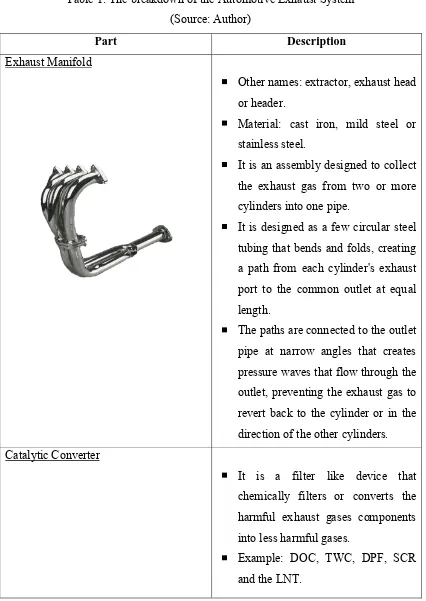
Table 1: The breakdown of the Automotive Exhaust System (Source: Author)
Part Description
Exhaust Manifold
Other names: extractor, exhaust head or header.
Material: cast iron, mild steel or stainless steel.
It is an assembly designed to collect the exhaust gas from two or more cylinders into one pipe.
It is designed as a few circular steel tubing that bends and folds, creating a path from each cylinder's exhaust port to the common outlet at equal length.
The paths are connected to the outlet pipe at narrow angles that creates pressure waves that flow through the outlet, preventing the exhaust gas to revert back to the cylinder or in the direction of the other cylinders. Catalytic Converter
It is a filter like device that chemically filters or converts the harmful exhaust gases components into less harmful gases.
9 Muffler
Other names: silencer.
Function: Noise reduction emitted by the engine.
It is designed to have a resonating chamber, which is specifically tuned to cause destructive interference, whereby the opposite sound waves hits and cancel out each other, resulting in the final noise reduction. Example noise frequency absorption material: Fiberglass.
Tailpipe and Tip
It is located at the end of the final length of exhaust pipe where it vents to the open air.
It is the most visible part of the entire exhaust system.
It is the final pressure reduction part of the entire exhaust system.
10
2.3 Exhaust Emission Compositions
The exhaust emission substances produced by both spark-ignition engine and diesel engine are similarly the same-HC, CO, NOx and PM. The exhaust emission from a spark-ignition engine has a much lower amount of NOx and PM if compared to the exhaust compounds of a diesel engine. However, in fuel economic wise, the diesel engine had proven to be the better choice. But due to the combustion process sets to occur towards the lean side, and also because of the present of Sulfur based compound in the fuel, the diesel engine tends to generate relatively large amount of NOx and PM emission, which requires various hard works to be done in order to fully utilize the diesel engine without reducing it’s engine performance. The following table presents the exhaust composition and exhaust gas temperature based on a few types on engines.
Table 2: Exhaust composition and exhaust gas temperature of different engine type (Source: G. C. Koltsakis, 1997)
2.3.1 NOx Formation in Diesel Engine
According to Bertrand D. Hsu, during the presents of Oxygen, over 90% of the formed NOx compound appears in the form of NO (Nitric Oxide) and NO2 (Nitrogen Dioxide). Other compounds such as N2O (Dinitrogen
Monoxide), N2O3 (Dinitrogen Trioxide), N2O4 (Dinitrogen Trioxide) and
N2O5 (Dinitrogen Pentroxide), appeared in negligible amount. These