!
! " ! # $ ! # %& ' ()
& * +++++++++++
* , #- ., / . '
$-& * 0 1232
& * +++++++++++++,,
* , 4 # ' #
& &4. -5 & 0 . & - 5 0 & # 6 &
-& - 7 . &0-6 # 6 .4 &0
8 9 0 5 : ' & '.,
! " ! # $ ! # %& ' (
5 $ ! #
4 ; & # #
ii
! "" # $ %
" # ! # & ' ' & (( )
*'' & + ( * ,
- * . /////0///////
* . 1 2 3 4 4 0 %
iii
& + ' * (* ( ' $ ( * + * &
iv
( $ & * 8 ) ' 8(* ' - (
-. ' - ' ' * * ' !
- - * ( + ! ! 9 !: (* (
;* ' ( ' 4 < - ! ( ' * 0
! ) & + (* *-- ' +
0 & 8 ' * + $ 0 ! 0 =
8 ( -* * - * $ " 0 ! *' !
= ' 0 4 $ & * 8 8 ' ( & - +
' ( - + - + - & * 0 $ ( *
* - $ ' " !*
! "" # $ % " # ! #
( ' - ( > * " #
5676 & !$ 8* 0
& * 8 ' & ' * ' $ ?4!#
* ' $ * ! & * ' ''
*-- 0 * $ ' + ' $ '
" $ ' * (* ( ' + $ !* ( ; ( * ' *
' - ' 0 1 * + $ '
v
( ' ( - + - + - ' * 8 +
( '' - + 0 - - @ ' * )
* * + - ' * 9> #:0 * $ $
-& * 0 * ' '
( ' ( ' - & 0 $ & - - ( '$
( ( 0 - ( ( +
- * & 8 - ' * ' - & ((
*' -0 * ( AB66 4 *C C(5 * *
8 ( & ) ' D 0 & + $ *' &
- * ) ' 7B66 4 *C C(5 ( +
' * & ' ;* 8 & 8 ( 0 * $ - (
( ' * ( - ' " *' *
'' " B57 9 " " B57:0 *
* - ( ( ' ' " 0 8
- * & * ( 0 ( - * $ 7 ! $
& ( & * & 60B ! 0 $
' ) '*' ( ' ( 8 ) * 8 ( ' " " B57
& - ' $ - ( ( 8 & 8 ( '
* - 0 ( $ ' ( ' - * ( * 8
vi
- 8 + ' 8 - ' * ' 8
' ' 8 8 - *8 8* 8 & * *
- -- 0 " ' 8 * 8 * * -- - -* 8
* *8 ' ' 8 - 8 ' * 0 8 *- ' - 8 $
8 - $ *- ' 0 - ' 8
8 * 8 ' ' *8 - ' - 8 ' - 80 ! 8 $
' 8 ' ' 8 $ * ( 8 - *
' -8 0 8 *8 ' ' 8 - * - '
* - 8 ' 8 *8 - ' ' 8 8 88
*- ' ' 8 ' * 0 E ' * *88 *
8 ' AB66 4 *C C(5 ' 8 8 8 8* 8* *
--8 ' D 0 4 - ' * $ ' * 9 8 : - 8
- * ' 8 ' -- 7B66 4 *C C(5 * *8
' ' ' 8 ' ' ' * 9 : ' 8*8 8
-8 & * 0 ' 8 $ 8 *8 ' ' 8
8*8 - ' * *8 8 ' " *' * '' "
B57 9 " " B57:0 * 8 - ' ' 8 8 *8 '
' 8 * ' ' * ( " 0 8 8 * @ * 8
-- ' ' 8 0 4 - 8 -- $ ( 7 ! $
' 8 * *8 8 & 60B ! 0 ' $ 8 '
8 ' 8 '*' 8 8
-' " " B57 ' 8 - * ' *8 $ 8
--- - - ' 8 *8 ' 0 - * $
- ' *8 - * * *8 ' ' 8 8 '
vii
+ + +
+ )
) )
707 * % 7
705 ' 5
70F ' - F
70? " ' ' ?
70B + B
70D ( * B
70A ) * B
viii
507 * G
505 ' H
50F ( 76
50? 8 77
50B - 75
50D 7?
50A * ' 7?
50G " + * 7D
50H (( ( 7H
F07 * 57
F05 ' - 55
F0F " '' " 55
F0? ' 5F
F0B #* - 5?
F0D + ' & # 5B
?07 * 5D
?05 - " * I & " * 5A
?0F ) " ' 5A
?0? ' - 5G
?0B ! 0 ( ' 8 F6
ix
B07 * FH
B05 ' - ?6
B0F - ?7
B0? 1 ?7
B0B ! '*' ( ' ?5
8
D07 * ?F
D05 ' - ??
D0F - ??
D0? 1 ?B
D0B * ?D
?A
D07 # * ?A
D05 '' ?G
x
?0F ' & ( ) + * 5H
?0? ' ( ( ' ( - & * F6
?0B - ( ( ' ( - * & * FB
?0B & + ( ( - * & * FA
B05 ' - (( ' ( " " ( 8 ?6
B0F ! '*' ( - * - ' ?7
xi
-* 7 (( ( ' 5
-* 5 " ( 7B
-* F (( ( 56
-* ? ! < ( ' 5?
-* B ' - + * 5D
-* D ' ( - & 5A
-* A ) ' ( ' * & F5
+ ( ' ( 8
-* G ' ( - & F7
-* H ) ' ( ' * & FB
+ ( ' ( 8
xii
7 "" K 7 B5
5 "" K 5 B?
F "" K F. BD
? "" K ?. " BG
B "" K B. #E BH
D "" K D. ! D6
D "" K A. " !" "" # ! D5
A "" K G. * ( DF
' $ % " '
xiii
" ' " *' *
" @ " ' " *' '' "
4 I 4 J* & 8 I ''
% ' %
%" % " *
" - " *
#" - # "
# - + *
" & " *
4*
0 ' *
1
CHAPTER I
INTRODUCTION
1.1 Introduction into General Topic
In heat transfer, heat is form of energy that flows from high temperature to low
temperature. There are three modes of heat transfer; conduction, convection and
radiation. Conduction is the transfer of energy from the more energetic particles of a
substance to the adjacent less energetic ones as a result of interactions between the
particles. Normally, it occurs in solids, liquids and gases. Convection is the flow of heat
through a bulk, microscopic movement of matter from a hot region to a cool region.
However, convection occurs on solid surface and it involves the combine effects of
conduction and fluid motion. Unlike conduction and convection, heat transfer by
radiation can occur between two bodies, even when they are separated by a medium
colder than both of them. Radiation is the energy emitted by matter in the form of
electromagnetic waves.
As offshore oil gas exploration realms begin to engulf new and increasingly
challenging environments the problem associated with the disposal of volatile organic
compound (VOC). Flaring is widely use at plan to dispose unwanted gases or relief
gases by burned those gases. Combustion is complete if all VOCs are converted to
carbon dioxide and water. However, incomplete combustion promotes VOCs unaltered
2
undesirable by-products including noise, smoke, heat radiation, light, SOx, NOx, COx,
and an additional source of ignition where not desired. Though, a proper design will help
to minimize these problems.
1.2 Flare System Application
The application of flare widely use in the oil, gas and petrochemical industry.
Flare means gas is disposed and consume as fire in an atmospheric area. Petrochemical
industry such as refinery plant, used flare to burned wasted gas or over-pressuring gas.
Either onshore or offshore, the wasted gas is burned out using flare that may cause effect
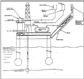
[image:16.612.148.472.357.663.2]of the emission. Figure 1 below showed the application of flare on offshore platform.
Figure 1: Offshore platform (Source: Gas Disposal, and Flare and Vent System
3
1.3 Flare System Technology
Flare system technology nowadays becoming more challenging as petrochemical
industry are in races to design the best system with considering some risks. The
consideration probably will be on the normal exit of waste gas or emergency exit,
means the over-pressuring gas. In the other hand, technology of design flare become
more widely as they consider the emission or heat radiated from the flaring activity
instead of soot or smoke.
High Pressure/Low Pressure Flare Package is an example for flare technology.
This example was referring to the Flareon Sdn.Bhd previous project. The system
consists of two different stacks. The stack is for high pressure flow and another one is
for low pressure flow.
1.3.1 Sonic High Pressure Flare
Sonic flares utilize multi-point exit nozzles to dispose of high pressure waste gas
streams. The MACH-1 Sonic Flare Tip utilizes the pressure of the waste stream
(creating sonic exit velocities) to create turbulent mixing and induce excess quantities of
air for more complete combustion.
The minimum HP purge rate of oxygen free hydrocarbon gas required to prevent
air entertainment thus any possible flashback within the Flare System is 314 SCFH
(8.9sm3/hr) for a 20mph(10m/s) wind.
1.3.2 Low Pressure Flare
The minimum LP purge rate of oxygen free hydrocarbon gas required to prevent
air entertainment thus any possible flashback within the Flare System is 79 SCFH
4
1.3.3 Flame Front Generation (FFG)
FFG is the simple backup system in case of the igniter (spark plug) failure. So,
flows of both Fuel Gas and Air are mixed together in a flammable ratio at a location
which is easily accessible to operating personnel, usually fairly close to the bottom of an
elevated flare. Then, the result is as though there is a “ball” of flame rolling along the
line at something between 10 – 70 fps (usually).
1.3.4 Ignition Control Panel (ICP) and Skid
Ignition control panel is a medium to control ignition at pilot. ICP contains push
button, pilot’s lamp to received signal from IDE either the pilot is ready to use or not.
Ignition Device Enclosure is a medium to transfer signal from thermocouple to ICP at
the bottom. Thermocouple which is use in this project is Single Element Type K
Thermocouple with Swage Connections (SS) for pilot. When the pilot is burning,
thermocouples will detected the heat of the flame and give a feedback to the control
panel. If failed, the control panel will be lighted red, but if success the control panel will
be lighted green.
Skid is structural steel frame to hold three bottle of propane gas, ICP box, FFG
transformer box and all instruments, tubing and fitting on it.
1.4 Problem Statement
As working at the most hazardous area, the design of flare system must be
correct to avoid any accident. When flaring, instead of expose to smoke, workers also
expose to heat radiation. The height of stack, opening diameter, and sizing should be
5
1.5 Objective
· To determine the minimum distance from a flare to exposure object.
· To study the effect of heat radiation towards equipment and life being.
· To achieve optimum level of operation.
· To define sizing of flare (diameter, height, opening)
1.6 Scope
The scope of study includes:
· Collecting information about heat radiation or flare.
· Review collected information.
· Analysis the heat radiation, the minimum distance from flare to exposure
object, the heat radiation of flare system towards personnel and equipment
and analysis of the sizing of flare.
· Analysis the current design of flare.
· The analysis will use NAO method and API Simple Approach
· Conclusion
1.7 Expected Result
After analysis, the minimum distance from a flare to exposure object could be
determined. Beside that, the sizing of flame length, diameter and percentage of different
can be defined. The minimum distance shall meet API Standard as well as the flame
6
1.8 Thesis Content
This project is divided into six chapters. Each chapter contains appropriate
information as it should have. Chapter I is an Introduction. In this chapter, there were
content of introduction into general topic, flare system application and technology, the
problem statement, objective, scope, expected result and thesis content.
A basic explanation of heat transfer consists in this chapter along with the
application and technology in flare system. A problem statement shall be clearly
understood before proceed to the next stage. The objectives are the main element in this
thesis is clearly clarified. Scope section included the task that shall do in purpose to
accomplish the objective of this thesis. Expected result as well as hypothesis is the
predicted result from this thesis. It is important to give an expected result as the final
result shall be compared with it. Last section in this topic is thesis content. Thesis
content is important as they shall summarize each chapter in one section.
Next chapter is Chapter II which is Literature Review. In this chapter, the deeply
elaboration of thesis is stated. It consists of the principle of flare, the previous research
summary, the fundamental of heat radiation and a hazard and operability (HAZOP). In
this chapter, the understanding of thesis topic is more to be understood. Referring to the
previous research, the methods used are different.
Chapter III is the Methodology. As it named as methodology, it is defined
method use in order to achieve objective line. The method use is the latest method by
American Petroleum Institute (API). The method is API Recommended Practice 521 a
Guide for Pressure Relieving and Depressuring System 4th Edition. The minimum
distance from exposure objects is determined by this method.
Chapter IV is the Data Analysis. The data is analyzed using two methods. There
were NAO method and API Simple Approach method. Both methods gave the different
result for the flame length and the minimum distance from flare stack to exposure object.
The analysis took an account for stagnant air (still air) and windy condition. However,
for stagnant air, there was only one method can be used. Some parameters are set to be
7
The next chapter is Chapter V, where all result is stated here. The results are for
both methods and air conditions were stated in a table as the different easier to see. The
minimum distance from flare stack to exposure object is stated at the last part of this
chapter. While in the next chapter, Chapter VI is a Discussion. In discussion section, the
result obtained is discussed. Finally is Chapter VII. The last chapter definitely shall be
the Conclusion. The overall project will be presented in the conclusion along with result
8
CHAPTER II
LITERATURE REVIEW
2.1 Introduction
Prior to 1947 in the United State of America, the process of vent streams were
directly exhausted to the atmosphere. Late 1947, regulations required that hydrocarbon
vent streams be safely burned or flared. Flares are designed to safely and efficiently
combust vent streams of combustible gases from the plant. They also must operate over
a wide range of conditions, from small purge rate flow to large emergency relief flow,
with vent gas compositions that are often highly variable. Large relief gas flow will
produce large flames. Thermal radiation, noise and visible smoke are all important
emissions that need to be minimized.
Flaring is high-temperature oxidation processes used to burn VOC. Commonly
are hydrocarbons, waste gases from industrial operations. Natural gas, propane,
ethylene, propylene, butadiene and butane constitute over 95 percent of the waste gases
flared. In combustion, gaseous hydrocarbons react with atmospheric oxygen to form
carbon dioxide (CO2) and water. In some waste gases, carbon monoxide (CO) is the
major combustible component. Presented below, as an example, is the combustion
reaction of propane.
9
During a combustion reaction, several intermediate products are formed, and
eventually, most are converted to CO2 and water. Some quantities of stable intermediate
products such as carbon monoxide, hydrogen, and hydrocarbons will escape as
emissions.
2.2 Flare System
A flare system provides a method of protecting equipment from overpressure or
in the other sentences is the safe disposal method of the released fluids. Usually, there is
another method of disposal system instead of flare. It is call a vent system. Roughly,
both of those methods have the same purpose. However, when flaring, it means the gas
is burned but when venting, it means the gas is discharged directly to atmosphere or
water.
Flaring is a combustion process which volatile organic compound are piped to a
remote, usually elevated and burned in an open flame in the open air using a specially
designed burner tip, auxiliary fuel, and steam or air to promote mixing for nearly
complete volatile organic compound destruction. Combustion is the rapid oxidation fuel.
This reaction produces heat, noise and light as well as pollutant such as NOx, COx and
H2O.
Basically, flare consists of flare stack, flare tip and pilot. As an electronic device
is located in control panel box, it is excepting to discuss instead of the report is about
mechanical part. Generally, flare stack is a tall vertical vent pipe use in petroleum
refineries, chemical plants and petrochemical plants oil and gas drilling sites, natural gas
processing plants, and landfills for burning off unusable waste gas or flammable gas
released by pressure relief valves during unplanned over-pressuring of plant equipment.
Flare tip is located at the top of flare stack. The functions of flare tip are to
burned or vent all of wasted gas to the air. As flare stack acts such a medium to transport
10
gases. The material usually use for flare tip is stainless steel (SS316). Pilot is controlled
by a system in a control panel box that is located in ICP Skid.
2.3 Types of Flare
Generally, flare can be categorized by two characteristic, first by the height of
the flare tip and second by the method of enhancing mixture at flare tip. For example
ground or elevated can be categorized as the first characteristic while steam-assisted, air
assisted, pressure-assisted and non-assisted can be put in the second group of
characteristic. Elevating the flare can reduce the risk of dangerous conditions at ground
level where the ignition is near the process unit. Furthermore, the product of combustion
can be dispersed above working areas to reduce the effect of noise, heat, smoke, and
objectionable odors.
Failure to destroy waste gases correctly is not a new issue although the problem
is increasing in profile due to legislation and corporate environmental focus over recent
years. In most flares, combustion occurs by means of a diffusion flame. A diffusion
flame is one in which air diffuses across the boundary of the combustion product stream
toward the center of mixture flow, forming the envelope of combustible gas mixture
around a core of fuel gas. This mixture, on ignition, establishes a stable flame zone
around the gas core above the burner tip. This inner gas core is heated by diffusion of
hot combustion products from the flame zone.
When the formations of small hot particles of carbon give the flame
characteristic luminosity it can occur cracking on flare stack. However, if there is an
oxygen deficiency and if the carbon particles are cooled to below their ignition
temperature, smoking occurs. Hence, an adequate air supply and good mixing are
required to complete combustion and minimize smoke to overcome this problem.
Consequently, the various design of flare takes part to overcome this problem.
As an example, to create smokeless operation, steam-assisted flare will be selected. It
burned vent gas in essentially a diffusion flame. To ensure an adequate air supply and