i
“ I hereby declare that I have read through this report entitle Mnemonic Code To Ladder Diagram Converter andfound that it has comply the partial fulfillment for awarding the Degree of Bachelor ofElectrical Engineering (Control, Instrument and Automation)”
Signature : ...
Supervisor‟s Name : MR. SHAHRUDIN BIN ZAKARIA
ii
MNEMONIC CODE TO LADDER DIAGRAM CONVERTER
NORIZAN BIN MAHMUD
A Report Submitted in Partial Fulfillment of Requirements for the Degree Of Bachelor in Electrical Engineering (Control, Instrumentation and Automation)
Faculty of Electrical Engineering
UNIVERSITI TEKNIKAL MALAYSIA MELAKA
iii
STUDENT DECLARATION
“I hereby declared that this report is a result of my own work expert for the excerpts that have been cited in the references”
Signature : ...
Name : NORIZAN BIN MAHMUD
iv
v
ACKNOWLEDGEMENT
In The Name of Allah the Most Merciful and Most Compassionate
First and foremost, I would like to thank to my supervisor of this project, Mr. Shahrudin Bin Zakaria for the valuable guidance and advice. He inspired me greatly to work in this project. His willingness to motivate us contributed tremendously to our project.
Besides, I would like to thank the authority of Universiti Teknikal Malaysia Melaka (UTeM) for providing us with a good environment and facilities to complete this project. Also, I would like to take this opportunity to thank to the Fakulti Kejuruteraan Elektrik (FKE) of Universiti Teknikal Malaysia Melaka (UTeM) for offering this subject, Control, Instrumentation and Automation (BEKC).
vi
ABSTRACT
vii
ABSTRAK
viii
TABLE OF CONTENTS
CHAPTER TITLE PAGE
ACKNOWLEDGEMENT v
ABSTRACT vi
ABSTRAK vii
TABLE OF CONTENTS viii
LIST OF TABLE xi
LIST OF FIGURE xii
LIST OF APPENDICES xv
LIST OF SYMBOL xvi
1 INTRODUCTION 1
1.1 Overview 1
1.2 Background 1
1.3 Problem Statement 1
1.4 Objective 2
1.5 Project Scope 2
1.6 Summary 2
2 LITERATURE REVIEW AND THEORY 3
2.1 Programmable Logic Controller (PLC) 3 2.1.1 The Conversion of Ladder Diagram to
Instruction List 4
2.1.2 The Conversion of Instruction List to
Ladder Diagram 4
2.2 Microsoft Visual Basic 6.0 5
2.3 Omron Cx Programmer Software 7
ix
CHAPTER TITLE PAGE
3 PROJECT METHODOLOGY 11
3.1 Introduction 11
3.2 Methodology of the Project 11
3.3 Project Flow Chart 12
3.4 Developing the Converter Software 13
3.5 Microsoft Visual Basic 14
3.6 Ladder Diagram in Converter Software 18
3.6.1 AND Ladder Rung 19
3.6.2 OR Ladder Rung 19
3.6.3 Branch Ladder Rung 20
3.6.4 Branch OR AND OR Ladder Rung 20
3.6.5 Latching Ladder Rung 21
3.6.6 Timer Ladder Rung 22
3.6.7 Counter Ladder Rung 22
3.7 Symbol Use in Converter Software 23
3.8 Summary 25
4 RESULT AND DISCUSSION 26
4.1 Introduction 26
4.2 Result 26
4.3 Experimental Results 26
4.4 Early Stage of Converter Software 27 4.5 Final Stage of Developing Converter Software 28
4.5.1 Converting Mode 29
4.5.2 Editing Mode 33
4.6 Analysis and Comparison 36
4.6.1 AND Ladder Rung 37
x
CHAPTER TITLE PAGE
4.6.3 Latching Ladder Rung 39
4.6.4 Branch OR AND OR Ladder Rung 40 4.6.5 Branch AND - OR - AND Ladder Rung 41
4.6.6 Timer Ladder Rung 42
4.6.7 Counter Ladder Rung 43
4.7 Discussion 44
4.8 Summary 44
5 CONCLUSION AND RECOMMENDATION 45
5.1 Conclusion 45
5.2 Suggestion 45
REFERENCE 46
xi
LIST OF TABLE
TABLE TITLE PAGE
4.1 Function of Control in Convert Mode 29
xii
LIST OF FIGURE
FIGURE TITLE PAGE
2.1 Ladder Diagram 4
2.1 Visual Basic 6
2.3 The Visual Basic Environment 6
2.4 Omron Cx Programmer Version 9 7
2.5 The Omron Cx Programmer Environment 7
2.6 Writing the Ladder 8
2.7 Display the Ladder 9
2.8 Writing the Mnemonic Code 9
2.9 Converting Mnemonic Code to Ladder Diagram 10
3.1 Project Flow Chart 12
3.2 The Initial Visual Basic Screen 14
3.3 Visual Basic‟s Code Window 15
3.4 Toolbox Window 15
3.5 Ladder diagram 18
3.6 Ladder Diagram for AND Function 19
3.7 Ladder Diagram for OR Function 19
3.8 Ladder Diagram AND - OR - AND Function 20
3.9 Ladder Diagram OR - AND – OR Function 20
3.10 Latching Ladder Rung 21
3.11 Timer Ladder Rung 22
3.12 Counter Ladder Rung 23
3.13 Normally Open Contact 23
3.14 Normally Closed Contact 24
3.15 Output 24
3.16 Output Timer 25
xiii
FIGURE TITLE PAGE
4.1 Prototype of Developing Converter Software 27
4.2 Main Menu Converter Software 28
4.3 Converter Program Window 29
4.4 The Result of Converter Software 31
4.5 Remove the Mnemonic Code 32
4.6 The Result after Remove the Mnemonic Code 32
4.7 Edit Mode Window 33
4.8 Replace the Mnemonic Code 34
4.9 The Result after Replace the Mnemonic Code 35
4.10 Add New Line the Mnemonic Code 35
4.11 The Result of Adding New Line Mnemonic Code 36
4.12 AND Ladder Rung (Converter Software) 37
4.13 AND Ladder Rung (Mnemonic Code - Cx Programmer) 37 4.14 AND Ladder Rung (Ladder Diagram - Cx Programmer) 37
4.15 OR Ladder Rung (Converter Software) 38
4.16 OR Ladder Rung (Mnemonic Code - Cx Programmer) 38 4.17 OR Ladder Rung (Ladder Diagram - Cx Programmer) 38
4.18 Latching Ladder Rung (Converter Software) 39
4.19 Latching Ladder Rung (Mnemonic Code - Cx Programmer) 39 4.20 Latching Ladder Rung (Ladder Diagram - Cx Programmer) 39 4.21 Branch OR AND OR Ladder Rung (Converter Software) 40 4.22 Branch OR AND OR Ladder Rung (Mnemonic Code –
Cx Programmer) 40
4.23 Branch OR AND OR Ladder Rung (Ladder Diagram –
Cx Programmer) 40
4.24 Branch AND - OR - AND Ladder Rung (Converter Software) 41 4.25 Branch AND - OR - AND Ladder Rung (Mnemonic Code –
Cx Programmer) 41
4.26 Branch AND - OR - AND Ladder Rung (Ladder Diagram –
xiv
FIGURE TITLE PAGE
4.27 Timer Ladder Rung (Converter Software) 42
4.28 Timer Ladder Rung (Mnemonic Code – Cx Programmer) 42 4.29 Timer Ladder Rung (Ladder Diagram – Cx Programmer) 42
4.30 Counter Ladder Rung (Converter Software) 43
xv
LIST OF APPENDICES
APPENDICES TITLE PAGE
xvi
LIST OF SYMBOL
PLC - Programmable Logic Controller VB - Visual Basic
GUI - Graphic User Interface
UTeM - Universiti Teknikal Malaysia Melaka NO - Normally Open
NC - Normally Close
TIM - TIMER
1
CHAPTER 1
INTRODUCTION
1.1 Overview
This chapter describes the introduction and purpose of this project, which is to develop the converter software. This project involves Visual Basic programming as a programming language and user interface. Introduction about the project includes the background of the study, the statements of problem, the objectives of the project, and scope of the project are explained.
1.2 Background
The title of this project is a Mnemonic Code to Ladder Diagram Converter. The purpose of this project is to design and develop Programmable Logic Controller (PLC) method converter which is ladder diagram and mnemonic code. Visual Basic 6 use to design the interface converter software.
1.3 Problem Statement
2
1.4 Objective
The main objective of this project is to develop and design the converter software by using Visual Basic which is able to convert the mnemonic code to ladder diagram for the PLC learning purpose. The software will display the ladder diagram according mnemonic code typed by the user. The specific objectives that are needed to accomplish the main goal are listed as follows:
1) To build the graphical interface using Visual Basic 6.
2) To create the education tool for students to improve their understanding the fundamental of the PLC.
1.5 Project Scope
In an effort to achieve the goal of this project, some scopes are outlined. The main scope of this project is to produce software that can convert mnemonic code to the ladder diagram. Then this software will automatically display the ladder diagram when the code mnemonic is typed.
This software will be developed based on existing programs that is Omron Cx Programmer. The process starts with understanding the technique and method used in this software as guidance for design this converter software. This software is comparable logical to Cx Programmer converter on Omron model only.
1.6 Summary
3
CHAPTER 2
LITERATURE REVIEW AND THEORY
2.1 Programmable Logic Controller (PLC)
A Programmable controller is a solid state user programmable control system with functions to control logic, sequencing, timing, arithmetic data manipulation and counting capabilities. It can be viewed as an industrial computer that has a central processor unit, memory, input output interface and a programming device. The central processing unit provides the intelligence of the controller. It accepts data, status information from various sensing devices like limit switches, proximity switches, executes the user control program store in the memory and gives appropriate output commands to devices like solenoid valves, switches, sensors, motor, indicator lamp more [1]. There were stipulated five programming languages in PLC programming language standard IEC6113 1-3:
1) Ladder Diagram (LD) 2) Instruction List (IL)
3) Sequential Function Chart (SFC) 4) Functional Block Diagram (FBD) 5) Structure Text (ST) [1].
4
2.1.1 The Conversion of Ladder Diagram to Instruction List
Though ladder diagram has the image intuitively in programming, yet it is composed by icons, it is a great difficulty in compiling ladder diagram directly and complex design. Therefore, it should convert ladder diagram to instruction list before compiling, due to the instruction list is similar to the assembly language and in accordance with the certain logic order by statement instruction, this form is easy to compile. Ladder diagram is connected in accordance with certain rule by symbol elements, thus it can map the elements of ladder diagram to the nodes of tree, the connecting line mapped to the connecting branch of tree [2].
2.1.2 The Conversion of Instruction List to Ladder Diagram
The relationship between instructions in instruction list and symbols of ladder diagram is one to one in PLC programming language; therefore the conversion of instruction list to ladder diagram is the inverse process of ladder diagram converts to instruction list. Ladder diagram is a kind of visual image symbol, instruction list is a kind of descriptive statement, and the key to transformation is extract relevant information from descriptive statement of instruction list to draw symbols of ladder diagram. For example, OR/ORB in instruction list and the parallel structure of ladder diagram, AND/ ANB and the tandem structure of ladder diagram in a corresponding relationship with one to one respectively [2].
5
Mnemonic Code
LD X6
OR X4
ORNOT Y2
AND X7
OUT Y0
LD X0
AND Y0
ANDNOT X7
OUT Y1
2.2 Microsoft Visual Basic 6.0
Visual Basic is a tool that allows user to develop Windows applications like Graphic User Interface (GUI). By using Visual Basic 6, users can create any programs depending on their objectives. Many programs can be creating with visual basic such as educational programs like program to teach science, mathematics, language, and history. An additional, users also can create a game program if they like those programs. The Visual Basic environment is shown in Figure 2.9 [7, 8].
Programming in VB is a combination of visually arranging components or controls on a form, specifying attributes and actions of those components, and writing additional lines of code for more functionality. Since default attributes and actions are defined for the components, a simple program can be created without the programmer having to write many lines of code. Performance problems were experienced by earlier versions, but with faster computers and native code compilation this has become less of an issue.
6
Figure 2.2: Visual Basic [9].
Figure 2.3: The Visual Basic Environment [9].
The Visual Basic Environmental consists of the follows:
1. Toolbox is contains the object component which is can be added to forms. 2. Form Design is a window used in application as platform to create program. 3. Project Explorer window view the lists of files used to build an application.
7
2.3 Omron Cx Programmer Software
Figure 2.4: Omron Cx Programmer Version 9
The Omron CX Programmer is a tool that allows user to program circuit and send into the PLC module. The program can be downloaded to the PLC module (CPU) either in ladder diagram or mnemonic code depends on user requirement. With CX programmer, users can create any ladder diagram circuit or write mnemonic code programs depending on their objectives. Besides that, user can convert their ladder diagram to mnemonic code or mnemonic code to equivalent ladder diagram. The Omron Cx Programmer environment is shown in Figure 2.5 [12].
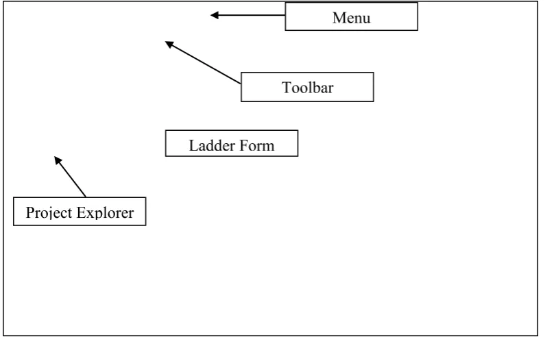
Figure 2.5: The Omron Cx Programmer Environment Project Explorer
Toolbar
Ladder Form
8
The Menu bar of the Cx Programmer screen displays the commands that can be used when working with Cx Programmer like File, Edit, View, Insert, PLC, Program, Window, Simulation, and Tool to provide commands specific programming. The Project explorer window is used to view the type of PLC CPU and file project.
A Toolbar is a collection of icons that carry out the standard symbol of ladder diagram when clicked. It includes normally open contact, output, timer, counter and so on. To program the ladder, components are chosen and type the address in command window controls as shown in Figure 2.6. The component will display depends to parameter that the user type controls as shown in Figure 2.7 [12].
Figure 2.6: Writing the Ladder
Address Command
![Figure 2.1: Ladder Diagram [2].](https://thumb-ap.123doks.com/thumbv2/123dok/570001.67417/20.595.171.435.549.738/figure-ladder-diagram.webp)
![Figure 2.2: Visual Basic [9].](https://thumb-ap.123doks.com/thumbv2/123dok/570001.67417/22.595.123.487.313.543/figure-visual-basic.webp)