DOI: 10.12928/TELKOMNIKA.v11i4.1642 661
Renewable Distributed Generation Models in
Three-Phase Load Flow Analysis for Smart Grid
Syafii*1, K. M. Nor2 1
Electrical Engineering Department, Andalas University, Padang, Indonesia 2Electrical Engineering Faculty, Universiti Teknologi Malaysia, Johor Baharu, Malaysia
*Corresponding author, e-mail: [email protected]
Abstrak
Makalah ini menyajikan model pembangkit energi terbarukan terdistribusi (RDG) tiga fase dalam perhitungan aliran daya dan analisis pengaruhnya ketika terhubung dalam sistem gabungan. Model RDG yang telah dibahas terdiri dari fotovoltan (PV) dan pembangkit turbin angin (WTG). Simpul kendali tegangan dan simpul injeksi daya komplek digunakan dalam pemodelan pembangkit. Pengembangan ini sesuai untuk aplikasi pada analisis sistem daya grid cerdas. Kombinasi data transmisi dan distribusi IEEE digunakan untuk menguji algoritma dalam masalah sistem distribusi tiga fase kondisi seimbang dan tidak seimbang. Hasil simulasi menunjukkan bahwa peningkatan jumlah dan ukuran RDG telah memperbaiki profil tegangan dan mengurangi rugi-rugi.
Kata kunci: aliran daya tiga fase, grid cerdas, pembangkit terdistribusi, photovoltan, turbin angin
Abstract
The paper presents renewable distributed generation (RDG) models as three-phase resource in load flow computation and analyzes their effect when they are connected in composite networks. The RDG models that have been considered comprise of photovoltaic (PV) and wind turbine generation (WTG). The voltage-controlled node and complex power injection node are used in the models. These improvement models are suitable for smart grid power system analysis. The combination of IEEE transmission and distribution data used to test and analyze the algorithm in solving balanced/unbalanced active systems. The combination of IEEE transmission data and IEEE test feeder are used to test the the algorithm for balanced and unbalanced multi-phase distribution system problem. The simulation results show that by increased number and size of RDG units have improved voltage profile and reduced system losses.
Keywords: distributed generation, photovoltaic, smart grid, three-phase load flow, wind turbine
1. Introduction
The fossil fuels such as coal, oil and natural gas are non-renewable, limited in supply and one day will be depleted. The price of this energy increase year by year related to decreasing in its availability. With the increase in the price of traditional petrochemical fuels for generation energy, the employment of renewable resource generation as alternative energy becomes more feasible, practical and realizable. Therefore, distributed generation (DG) using renewable energy sources will increase in recent years.
Distributed generation using renewable energy sources, such as wind, solar photovoltaic and hydro power has received considerable attention in recent years. Wind turbine generation (WTG) and photovoltaic (PV) are the world's fastest growing electricity generation technology. Global wind power capacity reached 94,100 megawatts by the end of 2007and available wind turbine sizes with capacities up to 3500 kW [1]. A lot of researchers have been studying the wind speed characteristics and its potential as a wind power generation in many countries worldwide [2]. Grid-connected PV production has been increasing by an average of more than 20 percent each year since 2002. At the end of 2009, the cumulative global PV installations surpassed 21,000 MW [3].
system analysis.
2. Research Method
The power flow analysis of a power grid containing distributed generation is the foundation of studying steady-state characteristics of future power system operation. The integration of RDG units be increasing and give the benefit contribution to existing grid power system operation, provide low-cost green energy, reduce transmission and distribution (T&D) losses and improve overall power quality and reliability [7].Distributed generations (DGs) are generally modeled as PV or PQ nodes in power flow studies for distribution system. However, the specified P, Q and V values depend on the type of DG. This research presents the modeling of wind turbine generation and photovoltaic as RDG units.
2.1. Wind Turbine Generator Modeling
A lot of researchers have been studying the wind speed characteristics and its potential as a wind power generation in many countries worldwide. The wind turbine generator unit in a load flow analysis can be modeled as PV bus or PQ bus. However, the WTG preferred model is as a PQ injection source rather than voltage controlled device (PV bus). The general wind turbine model using basic speed and power relations presented in [8] to calculate the output power is given by: the wind speed in m/s, and is rotor efficiency.
The power output can also be taken from power-speed curve provided by the manufacturer. The different companies provide different wind turbine curve. By using the curve wind speed can be plot to find specified power input in power-flow calculation.
The reactive power (Q) is specified or if power factor, cos , is specified, Q is calculated by using:
Q= -P tan (cos-1) (2)
The more accurate model, P and Q calculated from Induction (asynchronous) generator parameters using the equation 3.
∗
(3)
Where: is mechanical power, Za, Zb and Zc calculated from steady-state representation of the asynchronous machine parameters, is rotor voltage.
In this paper, the sequence components three-phase power-flow algorithm and model [8] are used for developing three-phase WTGs model. The new class library to model WTG has been added in object oriented power system model [9,10] using visual C++ programming.
2.2. Photovoltaic Model
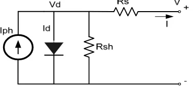
Figure 1. Photovoltaic model
The practical equivalent circuit of PV panel consists of a current source in parallel with a diode and inclusion of additional series resistance (Rs) and shunt resistance (Rsh) as shows in Figure.1. The value of current and voltage are depending on the solar irradiance and the ambient temperature.
The voltage-current (VI) equation of PV panel [11] is given by:
Rp
Iph: the current generated by the incident light (directly proportional to the sun irradiation), I0 : the reverse saturation of the diode,
q : the electron charge (1.60217646 x 10¹⁹ C), k : the Boltzmann constant (1.3806503 x 10⁻²³ J/K), T : temperature of the p-n junction,
Ns : number of cells connected in series and a is the diode ideality constant. Rs : the equivalent series resistance
Rp : the equivalent parallel resistance
The light generated current, Iph is calculated depending on solar radiation and temperature as follows:
, ∆ (5)
Where:
, : the light-generated current at the nominal condition
: current coefficient
∆ : the different of actual and nominal temperatures, G : the irradiation
Gn : the nominal irradiation respectively
The reserve current saturation is given by equation 6:
∆
∆ / 1 (6)
Where:
: voltage coefficient
/
The parameters required which can be obtained from the manufacturer’s module specifications include short-circuit current, open-circuit voltage, and temperature coefficients.
zero using Newton Raphson based nonlinear equation. However if the module is fixed the incidence angle will determine the effective irradiance value. The value of the calculated solar module output power is then used as an input to the load flow as a PQ bus with Q set to be zero.
3. Description of The Test System
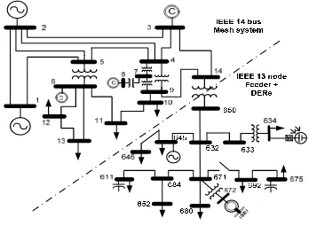
The proposed model tested and analyzed using Standard IEEE data and it combination without and with DGs. The combination of IEEE 14 bus [12] and IEEE 13 node feeder [13] used to test and analyze the algorithm in solving balanced/unbalanced active systems. The combination of IEEE 14 bus data and IEEE 13 node radial feeder known as the composite system shows in Figure 2.
Figure 2. IEEE 14 bus + 13 node test feeder with Cogen, PV and WTG connected
In RDG analysis, three DG units from different kinds of DG technologies were installed in three different locations. A cogeneration DG was directly connected to node ID 645, a PV was connected to new node ID 672 via step down transformer connected to node ID 671 of original node and a WTG was connected at the original node ID 634. The load flow analysis was performed by using per-unit values on a base 100 kVA and was solved for 0.0001 phase voltage mismatch.
and case 4 represented DG supply from Cogen and WTG units due to the absence of PV generation during the sunset. The case 5 shows the hybrid system during all DERs units connected.
4. Results and Analysis
Simulation results for this test case are summarized in Table 1. The results show that, the voltage is increased with the increase number and size of DG units installed in the network. The worst voltage result is in Case 1 which has no DG unit installed in the system. Case 5 has the best result with all DGs connected in the network. In this case, the voltages at all nodes are already within the permissible voltage violation. The maximum voltage is 1.09 p.u., similar to the specified value of bus ID 8 in the original IEEE 14 bus system.
Table 1 The Results of IEEE 14 bus + 13 node test feeder with DG
NEMA: National Electrical Manufacturers Association
The increased number and size of DG units installed in the network have decreased Voltage Unbalanced Factor (VUF) to below 5% as shown in Table 1.
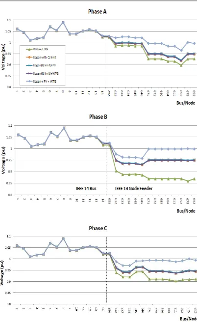
The effect of DGs in the composite system IEEE 14 bus and IEEE 13 node feeder on voltage profile are given in Figure 4 for the three-phases. The results show that, the voltage is increased by increasing number and size of DG units installed in the network. The lowest voltage curve is in Case 1, where there is no any DG unit installed in the system. Case 5 gives the best result where cogeneration modeled as PV node. In this case, the voltage nodes are slightly higher than cases 2–4, which correspond to the partial DG installation and cogeneration modeled as PV node with Q limit. If the Q limit is used, the PV node will be automatically converted to a PQ node, when Q limit is achieved. In this case, the cogeneration will operate as a PQ injection source rather than voltage controlled device. However, the reactive power generation from the DG units for Case 5 is the highest i.e. 2371.6 KVAr to maintain the voltage at cogeneration node equals to 1.0 p.u.
The voltage patterns for system 14 bus for three-phase are the same due to the fact that this system is actually a balanced system. The maximum voltage is 1.09 p.u. at bus ID 8. This value is the same as the specified value of the original IEEE 14 bus system for generation bus. The voltage variations among phases are shown in Figure 3 for the 13 node feeder, which is an unbalanced system.
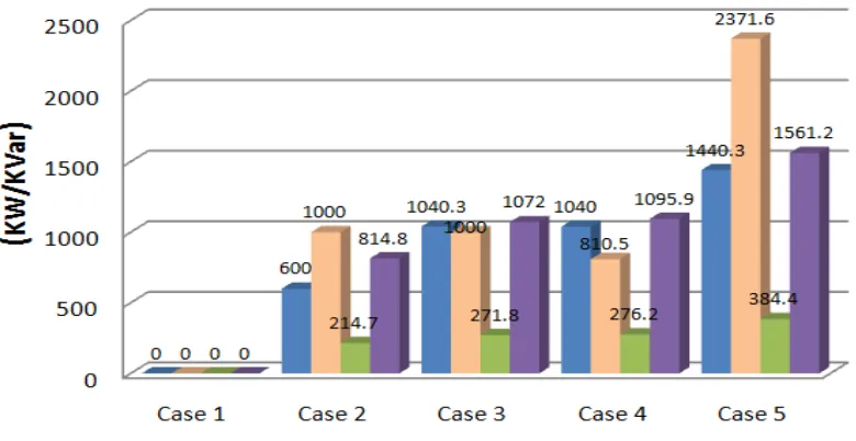
Figure 4 shows the DG generation and system loss comparison for all the cases. Losses for Case 1, which corresponds to no DGs, are used as base case. The results show that, the increased number and size of DG units installed in the network have decreased system losses or increased loss reduction.
Figure 4. DG Generation and Loss Reduction of the composite system
4. Conclusion
The paper has presented renewable distributed generation (RDG) models as three-phase resource in load flow computation. The RDG models that have been considered comprise of photovoltaic (PV) and wind turbine generation (WTG). The voltage-controlled node and complex power injection node are used in the models. These improvement models are suitable for smart grid power system analysis. The variation of wind speed (m/s) for WTG, solar radiation (W/m²) and temperature (°C) for PV have been simulated. The simulation results show that the proposed DG model can be used to analyze DG impacts in the unbalanced meshed and radial distribution system. The integration of DG into an existing distribution network can improve the voltage profile, decrease VUF and reduce total system losses.
Acknowledgment
The author gratefully acknowledge the assistance rendered by the Faculty of Engineering, Andalas University for partially funding this research in DIPA FT Unand 2013(Contract No. 008/PL/SPK/PNP/FT Unand/2013).
References
[1] Herbert GMJ, Inayan S, Sreevalsan E, Rajapandian S. A Review of Wind Energy Technologie Renewable and Sustainable Energy Reviews. 2007; 11(6): 1117-1145.
[2] [Daut I, Irwanto M, Suwarno, Irwan YM, Gomesh N, Ahmad NS, Potential of Wind Speed for Wind Power Generation In Perlis, Northern Malaysia. TELKOMNIKA International Journal, 2011; 9(3): 575-582.
[3] REN21. Renewable Energy Policy Network for the 21st Century. Renewables Global Status Report 2009.
[4] [Dugan RC, Arritt RF, Mc Dermott TE, Brahma SM, Schneider K. Distribution System Analysis to Support the Smart Grid. IEEE Power and Energy Society General Meeting. Minneapolis. 2010: 1-8. [5] Petinrin JO, Shaaban M. Overcoming Challenges of Renewable Energy on Future Smart Grid.
TELKOMNIKA International Journal. 2012; 10(2): 229-234.
[6] Kamh MZ, Iravani R. Unbalanced Model and Power-Flow Analysis of Microgrids and Active Distribution Systems. IEEE Transactions on Power Delivery. 2010; 25(4): 2851-2858.
[7] Kroposki B, Lasseter R, Ise T, Morozumi S, Papathanassiou S, Hatziargyriou N. A look at microgrid technologies and testing projects from around the world. IEEE Power and Energy Magazine. 2008; 6(3): 40-53.
http://www.ee.washington.edu/research/pstca/.