THE DESIGN AND FABRICATION OF AN OIL VACUUM CLEANER FOR INDUSTRIAL USE
NORHAFIS BIN SAMAT
UNIVERSITI TEKNIKAL MALAYSIA MELAKA
STUDENT DECLARATION
“I hereby declare that the work in this report is my own except for summaries and quotations which have been duly acknowledge.”
Signature : ... Author : ... Date : ...
SUPERVISOR DECLARATION
“I hereby declare that I have read this thesis and in my opinion this thesis is sufficient in terms of scope and quality for the award of the degree of Bachelor of Mechanical Engineering (STRUCTURE AND MATERIALS)”
i THE DESIGN AND FABRICATION OF AN OIL VACUUM CLEANER FOR
INDUSTRIAL USE
NORHAFIS BIN SAMAT
This thesis is submitted as a part of the fulfillment for the bestowal of Bachelor in Mechanical Engineering (Structure and Materials) with honours.
Faculty of Mechanical Engineering Universiti Teknikal Malaysia Melaka
ii ACKNOWLEDGEMENT
iii ABSTRAK
iv ABSTRACT
v TABLE OF CONTENTS
CHAPTER CONTENTS PAGE
PENGAKUAN PELAJAR
SUPERVISOR DECLARATION
ACKNOWLEDGEMENT ii
ABSTRAK iii
ABSTRACT iv
LIST OF TABLE vii
LIST OF FIGURE viii
LIST OF ABBREVIATIONS x
CHAPTER 1 INTRODUCTION 1
1.1 Background 1
1.2 Problem statement 2
1.3 The objective and hypothesis 2
1.4 Research scope 3
1.5 Project overview 3
CHAPTER 2 LITERATURE REVIEW 5
2.1 History of vacuum cleaners 5 2.2 Principle of vacuum energy 8
2.2.1 Composition of air 10
2.2.2 Ideal gases 11
2.3 Vacuum concepts 13
vi 2.4 Comparison of models available in market 15
CHAPTER 3 METHODOLOGY 18
3.1 Flow Chart 18
3.2 Quality Function Development (QFD) 21 3.3 Flow chart for engineering design process 21
3.4 House of Quality 22
3.5 Product Design Specification 24
3.6 Physical Description 25
3.7 Pugh Concept 27
3.8 Morphological chart 28
3.9 Configuration Design 29
3.9.1 First concept 29
3.9.2 Second concept 29
3.9.3 Third Concept 30
CHAPTER 4 RESULT AND DISCUSSION 35
4.1 Selection and Material 35
4.2 Fabrication Process 36
4.3 Testing and Prototype 37
4.3.1 Calculation Analysis 44
CHAPTER 5 CONCLUSION AND RECOMMENDATION 50
5.1 Conclusion 50
5.2 Recommendation 52
REFERENCES 53
vii LIST OF TABLE
NO TITLE PAGE
2.1 Comparison of cost, power and weight of vacuum cleaners 7 2.2 Conversion factors for pressure in various system of units 10 2.3 Composition of atmosphere (at sea level) 11 2.4 Lists of model available in market 15 3.1 House of Quality project House of Quality project 22 3.2 Pugh concept for material selection 27 3.3 Morphological Chart for Concepts 28
4.1 Components in AOV 35
viii LIST OF FIGURE
NO TITLE PAGE
2.1 Vacuum First Model 6
2.2 Vacuum Second Model 6
2.3 Vacuum Third Model 7
2.4 Vacuum Fourth Model 7
2.5 Experiment on atmospheric pressure 9 2.6 Conventional Household Vacuums 13
2.7 Bernoulli’s equation 14
2.8 Model A from Zhejiang, China 15
2.9 Model B from Zhejiang, China 16
2.10 Model C from Incheon, South Korea 16 2.11 Previous model used in industry 17
3.1 Flow Chart for PSM 1 19
3.2 Flow Chart for PSM 2 20
3.3 Flow Chart of Design Process 21
3.4 Nozzle 27
4.1 Exploded View of Nozzle 38
4.2 BOM of AOV 39
4.3 Full Drawing of Wheel 40
4.4 AOV Prototype Final View 41
ix container
x LIST OF ABBREVIATION
CAD Computer Aided Design
CAE Computer Aided Engineering
FYP Final Year Project
AOV Apez Oil Vacuum
DTY Draw Texturizing Yarn
PVC Polyvinylchloride
RM Malaysia Ringgit
Pressure at point 1(Initial)
Pressure at point 2(Final)
Q Flow rate
Cubic meter
Density of air
Density of coning oil
A Area
1 CHAPTER 1
INTRODUCTION
1.1 BACKGROUND:
A vacuum cleaner is an electrical household appliance that is used to clean floors, carpets, furniture and some time in our car. A vacuum cleaner sucks up dusts and dirt by creating a partial vacuum using an electrical air pump. The air is forced to flow through a filter where the dust and dirt are captured. Vacuum cleaners are also used in industries to clean all sorts of waste such as oil spill, hazardous dust and machining waste. Although both domestic and industrial vacuum cleaners work based on the same principle, the industrial vacuum cleaners are specially designed to suit the intended application environments such as factories, construction sites or machining workshops.
2 oil spill. The detail specifications of the current vacuum cleaner will be discussed in the next chapter.
1.2 PROBLEM STATEMENT
A general purpose industrial vacuum cleaner is normally used at Recron to clean the oil spill. However, it was observed that the use of this vacuum cleaner was not suitable if the oil temperature was high especially when the machine was operating. Although the existing vacuum cleaner is marketed as industrial use product, from the design aspect the material selection process was made mainly to reduce costs and therefore many of the main components are made of plastics. Even though engineering plastics are known for its durability however the main drawback is that the low melting temperature of these plastic materials causes some of the components to melt when it is used at high temperatures. Common issues when dealing with hot oil are leaking bin or tank; and melted hoses. There are special types of industrial vacuum cleaners that are suitable for high temperature applications however the unit price is very high. The cost of replacing or repairing a malfunction vacuum cleaner could be costly and time consuming. Therefore, a new innovative and low cost design of an industrial vacuum cleaner that can be operated at high temperature is needed.
1.3 THE OBJECTIVE AND HYPOTHESIS
3 1.4 RESEARCH SCOPE
1) To identify the design requirements for a low cost industrial vacuum cleaner. Several concepts will be list out and comparing each of their best criteria. The engineering design tools for specified the requirement will be applied.
2) To use Computer Aided Design (CAD) and Computer Aided Engineering (CAE) in the design and analysis process. It will be design software such as Solidwork and material selection such as CES Edupack.
3) To fabricate a working prototype of a low cost oil vacuum cleaner. To obtain the low cost prototype, most of the main material used will be recycled material with some improvement to achieving the objective. Before fabricated it, some material selection will be conduct to support the suggesting material.
4) To conduct prototype testing under actual working conditions. After fabricating it, testing and refinement will be carried out. The testing area will be around the actual working condition with supervised from skillful technician. There will be refinement step if error or malfunction occur during testing process for directly troubleshoot problems.
1.5 PROJECT OVERVIEW
Chapter 1 will explained briefly about the purpose of this project and how this project is chosen. It will include background of the project, problem statement, objectives and research scope. Basically, the project generated while undergone industrial training. The problem arises when one of the vacuum cleaner was broken down due to high temperature.
4 The purpose is to suggest material which best to withstand high temperature and produce in low cost.
Chapter 2 will includes history of vacuum and how it evolved, principles of vacuum that is the main concept in this project, and comparison of product that mainly produced by other region beside Malaysia. The history helps in understand how this vacuum concept is applied for better used. Meanwhile for the comparison, many manufactures are not from Malaysia, so, the cost is quite high with shipping and the product cost itself.
Chapter 3 including Quality function development, engineering design process, house of quality, product design specifications, physical description, Pugh concept, morphological chart and configuration design. Several materials will be choosing to compared and be select as the best material. From that, other features will be added to help in making better design. All that features will also be compared with the advantage and disadvantage. Finally, one model will be selected which is the best from other model to fulfilled the purposed of this project and will undergoing testing and refinement after done in fabricating it.
Chapter 4 emphasize on result and discussion. This can be divided into three categories which are selection of material, fabrication process and testing the prototype. With selected design and material, the fabricated process and testing process is conducted in actual working condition. The testing is conducted two times for ensuring its function in the first test and second is for operate in working station. Sample calculation also constructed to check on flow rate that exist in the project.
Chapter 5 is conclusion and recommendation that involve on the outcome gained through one year by completing this project such as acquiring new knowledge and also gaining priceless experience. Other than that, some recommendation is add so that for future sake, better improvement can be employ.
5 CHAPTER 2
LITERATURE REVIEW
2.1 HISTORY OF VACUUM CLEANER
6 Figure 2.1: First generation of vacuum cleaner (Ashby, 2012).
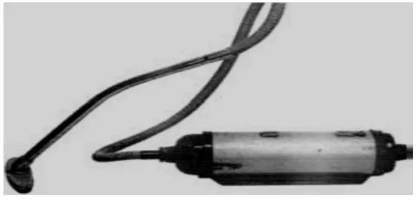
Meanwhile, the electric vacuum cleaner was first appeared around 1908. During 1950, cylinder cleaner is formed shown in Figure 2.2 (flow rate about 10L/S). The principal for this design can be described as air flow is axial, electric fan will draw it through. The electric fan will occupied about half diameter of cylinder where the rest will holds the filter. Following that, advancing in design is achieved when electrically driven air pump is invented. The motor are thick and have flow power and can function properly without housemaid’s elbow or tea breaks. It is totally made up of metal and include the tube that suck up dust are made up of mild steel which metals have entirely replaced all natural materials.
Figure 2.2: Second generation of vacuum cleaner (Ashby, 2012).
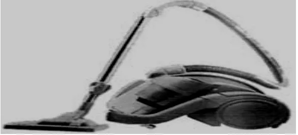
7 (800w) and double up the power (Ashby 2012). For the air flow is still longitudinal and dust removal by filtration technique. This is due to higher power density inside the motor that operate, induced better magnetic field, and higher operating temperature (bearings, insulations, heat resistant and windings). The outer part is totally polymer and another example of good design that involved plastics. The top part is single molding with some extra bits joint by snap fasteners molded into original component. Number of components had surprisingly reduced with casing had only 4 parts, held by 1 fastener contrary to previous 1950 cleaner that consists 11 parts and 28 fasteners.
Figure 2.3: Third generation of vacuum cleaner (Ashby, 2012).
Although the sources on polymer are quite limited during that time, cost saving and weight is greater as shown in Table 2.1 (Ashby 2012). Next for Figure 2.4, it shows a different concept which is inertial separation rather than filtration. To work this concept, rotation and power have to be higher than, product is larger and higher cost.
8 Table 2.1: Comparison of cost, power and weight of vacuum cleaners (Ashby, 2012)
Thus, development design requires the innovation and creativity to use either new materials or recycled materials properties, both aesthetic and engineering. There are many manufacturers of vacuum cleaners cannot improvised rather innovate or create for better use in the future.
2.2 PRINCIPLE OF VACUUM ENERGY
The main concept in this project is manipulates the vacuum or air pressure that available in the production line. But first, vacuum concept needs to be expressed clearly. Vacuum is obtained from Latin word that is vacua, which is empty. Vacuum is just only half of empty space, whereas some of other gases and air have been removed from a gas containing volume (gas is defined from Greek word chaos = infinite, empty space). For simple word is, vacuum defined as any volume consists of less gas particles, atoms and molecules ( a lower particle density and gas pressure) compared to surrounding outside atmosphere. Starting from well-known Greek philosophers, Demokritos (460-370 B.C) and his teacher Leukippos (5th century
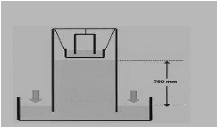
9 experiment carried out by scientist and philosopher from French named Blaise Pascal (1623-1662), stated that horror vacui was proved wrong as in Fig 2.5. He also measured the altitude with the Hg barometer was invented by Torricelli, provide enough into the concept of vacuum physics and gives many vital knowledge in physics. Thus, unit for measure degree of vacuum by the International Standards Organization (ISO) of pressure was known as honor of Pascal (Neils Marquardt 1999):
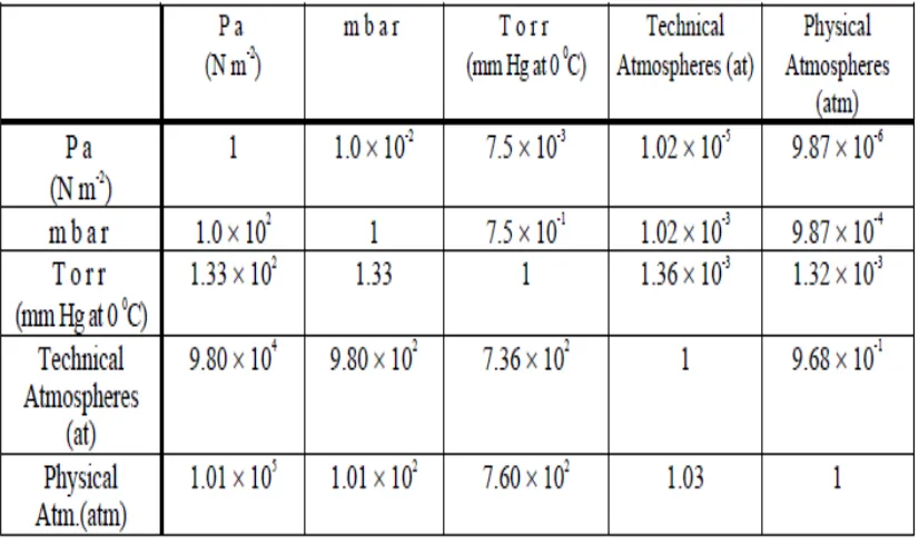
1 Pa = 1 N/m2 = 7.501 x 10⁻³ Torr =10-2 mbar
Figure 2.5: Experiment by Blaise Pascal proving the existing of atmospheric pressure with vacuum (Niels Marquardt, 1999).
Other significant discovery was through Robert Boyle (1627-1691) that built vacuum pump with Edme Mariotte in year 1627-1684 (Neils Marquardt 1999). They expressed that the law of Boyle-Mariotte, the fundamental equation of gas law that was valid for ideal gases in thermodynamically equilibrium, (p=pressure, V=volume and T=absolute temperature of gas)
10 Table 2.2: Conversion factors for pressure in various systems of units
2.2.1 Composition of air
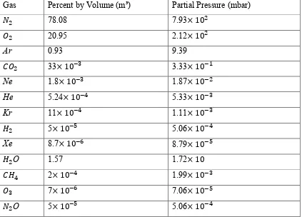
11 Table 2.3: Composition of atmosphere (at sea level)
Gas Percent by Volume (m³) Partial Pressure (mbar)
78.08 7.93
20.95 2.12
Ar 0.93 9.39
33 3.33
Ne 1.8 1.87
He 5.24 5.33
Kr 11 1.11
5 5.06
Xe 8.7 8.79
O 1.57 1.72
2 1.99
7 7.06
O 5 5.06
(Niels Marquardt, 1999)
2.2.2 Ideal gases
For the theoretical concept related with ideal gas is very applicable for characterization of vacuum-physics completion. There are several assumptions such as (a) molecules shape are small spheres (b) the density of the gas is approximately small, example is volume of molecules is miniature differ to volume of filled with gas (c) molecules that not applying forces to another, i.e. the temperature obtained for the gas is not quite low, (d) flow of molecules is continuous and irregular and (e) the contact between molecules is elastic. In this normal conditions, conversion from one state of a gas state, given by that is pressure, thermodynamic temperature