THREE PRE-PROCESSING STEPS TO INCREASE THE QUALITY OF KINECT RANGE
DATA
M. Davoodianidaliki a, *, M. Saadatseresht a
a Dept. of Surveying and Geomatics, Faculty of Engineering, University of Tehran, Tehran, Iran - (mdavoodian,
msaadat)@ut.ac.ir
KEY WORDS: Accuracy, Registration, Point Cloud, Edge Detection, Close range, Range-Image, Kinect
ABSTRACT:
By developing technology with current rate, and increase in usage of active sensors in Close-Range Photogrammetry and Computer Vision, Range Images are the main extra data which has been added to the collection of present ones. Though main output of these data is point cloud, Range Images themselves can be considered important pieces of information. Being a bridge between 2D and 3D data enables it to hold unique and important attributes. There are 3 following properties that are taken advantage of in this study.
Firstattributetobeconsideredis‘NeighborhoodofNullpixels’whichwilladdanewfieldaboutaccuracyofparametersinto point cloud. This new field can be used later for data registration and integration. When there is a conflict between points of different stations we can abandon those with lower accuracy field. Next, polynomial fitting to known plane regions is applied. This step can help to soften final point cloud and just applies to some applications. Classification and region tracking in a series of images is needed for this process to be applicable. Finally, there is break-line created by errors of data transfer software. The break-line is caused by loss of some pixels in data transfer and store, and Image will shift along break-line. This error occurs usually when camera
moves fast and processor can’t handle transfer process entirely. The proposed method performs based on Edge Detection where horizontal lines are used to recognize break-line and near-vertical lines are used to determine shift value.
Interface devices (NUI) with structured light technology. Microsoft Kinect(“Kinect for Windows,” 2013) and Asus Xtion(“Xtion PRO,” 2013) are most known among this generation. Raw data usually demands for some pre-processing step to get it ready for further processes.
The most known and common process on range data is calibration(Staranowicz and Mariottini, 2012) where some main sensor and lens distortions are rectified. But range data due to its unique properties can undergo more sophisticated processes to increase its accuracy and precision.
Among processes known for depth data, temporal filtering is most common(Matyunin et al., 2011). In this method occluded areas from one image is filled using neighbour images after shift computation. This can be applied to fill an image or output that can be point cloud. Other simple smoothing filters are no longer applicable since geometrical precision can be reduced. Constrained smoothing can be used to avoid overall image smoothing but still edges will be smoothed(Chen et al., 2005). Even without pre-processing of range images, it’s possible to register point cloud using algorithms such as ICP(Izadi et al., 2011) or confidence-based(Liu et al., 2011). Such methods in registration step reduce conflict effect among different stations. This paper presents 3 independent processes that can be applied on range images based on application. First process is Neighbourhood of Null pixels which add a new field to output data for further process. Polynomial fitting though called pre-processing is actually a step at final stage of some applications. Break-line removal as final introduced method is a process to avoid abandoning an entire frame. After introduction of
mentioned methods, an experimental section evaluates results after applying some algorithms on test data and finally conclusion section reviews overall process with pointing out some important matters.
2. PROPOSED PROCESSES
This section presents a description of proposed processes in order that if required can be applied.
2.1 Neighbourhood of Null pixels
Being out of range, unnatural reflection ability and other cases that might prevent Kinect from recording depth values cause pixels with no real observed value and here they are called null pixels. If camera is fixed, the most unstable pixels are those near edge pixels where they switch between a value and null. Neighbour pixels in this case are 8 surrounding pixels. Though value acquired in this pixel is likely correct, pixel coordinates are not and if this data is used to create point cloud, edges will be fuzzy (Figure 1). Directly removing this data might reduce precision so adding a field in which accuracy values are stored is recommended. The value of this field changes from 0 to 1 where 0 means Null pixel and 1 means range value without any neighbour of null (Figure 2). At the same time, single pixels with a value within a neighbourhood of null pixels are valuable since they provide a generic value of surrounding.
This new field can be used later for data registration and integration. When there is a conflict between points of different
stationswecanabandonthosewithloweraccuracyfield.It’sa
lot easier and not only increases accuracy in relative parameters also can reduce overall volume of point cloud.
Conflict might be different based on case of study. If except for floor and ceil of environment, there is just one altitude level then required processes are a lot easier. It means if there is any
a)
b)
Figure 1. Fuzzy edges in a) raw range image b) point cloud.
Figure 2. Accuracy field values based on number of null neighbor pixels with 0 as null pixel and most accuracy value of 1 as a pixel with no null neighbor.
object with the same 2D spatial coordinates, they must be attached (Figure 3).
For more complicated 3D models where at the same 3D coordinate, there are two points like two sides of curtain (Figure 4.a), required process in data registration is not easy as previous
Figure 3. Simple 3D model of single height level except floor and ceil(Marbelar, 2013).
a)
b)
Figure 4. Complex 3D model of different height levels: a) due to a thin surface such as curtain(Victor, 2013). b) because of thin bars that form the body of main object(“MonsterGT4.6
RollCage,”2013).
case (Izadi et al., 2011) but adding accuracy field is more meaningful since more conflicts can occur (Figure 4).
Even pixel coordinate shift is possible that means if a null neighborhood such as Figure 2 occurs, then we can assume that pixel is on edge and split it. If further processes such as edge detection are applied on data, then this level can be utilized with more certainty. A line can be fit to extracted edge and pixels of line with a width of 3 to 5 pixels get accuracy value of 0.5. If same edge is visible in different stations, edge will be decided by sum of accuracy filed in different stations.
Temporal filtering introduced by (Matyunin et al., 2011) is somehow a similar simple and practical process in this category. 2.2 Polynomial fitting
3D modelling for augmented reality purposes requires smoother data for geometrical reconstruction. Usually there are lots of planar surfaces especially in indoor environments such as floor, ceil and lots of indoor furniture like tables. If these planar surfaces are recognized, a partially model-based reconstruction can be utilized(Kien, 2005). This means that selected surfaces though part of point-cloud, can be recognized later and treated specially using a constraint.
When reviewing range matrix of a planar surface such as wall, this point demonstrate itself better since some neighbour pixels have the same range value despite their different distances. This
Figure 5. Range Contour of a planar surface. Thick red line with 3 to 5 pixels width is representations of deficiency in distance distinction (Image: Kinect camera calibration field).
Problem intensifies by growing distance between camera and object. To display this deficiency, a unique method of range image representation is utilized which is contours (Figure 5). Red colour in image is representation of a specific range value that its width is more than just one pixel all along.
First step that enables this entire process is classification. In object detection applications, classification is almost necessary and a required step for polynomial fitting is already applied. But main requirement for this process is surface tracking in which specific regions in a series of images are tracked and there must be an attribute to define that these regions are the same. Just surface tracking alone can increase precision on registered data by reducing confliction.
If accuracy field from previous section is also available, this process can affect some accuracy values. If pixels are part of surface, then accuracy filed must change into 1 since even if part of pixel is edge, range value is on surface.
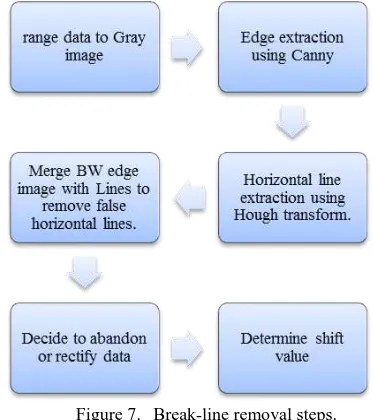
2.3 Break-line removal
Finally, there is break-line created by errors of data transfer software. Between different drivers available for Kinect, OpenNI, Microsoft SDK and Open Kinect are most common. But CLNUI(Laboratories., 2011) is a simple driver dependent just on OpenCV(“OpenCV,” 2013) library and provides RGB and processed depth image.
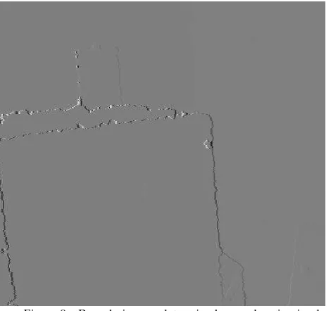
Data is continuously being transferred between computer and Kinect and break-line is usually caused by loss of some pixels during this process or due to hard disk error. This means Image will shift along break-line (Figure 6).
We can select other software products which automatically avoid this error by abandoning a frame when a series of bits is
lost but that doesn’t solve the problem. This error occurs
usually when camera moves fast and processor can’t handle transfer process entirely. This is exactly when we need a higher
rateofimagesandcan’taffordtolosean entire frame of data. This process consists of two stages of recognition and correction. At first step, Automatic recognition of this error is not an easy process since manual check will give the best result. The method which is proposed here performs based on Edge Detection. Though there are lots of edges in just one image, but there are seldom edges that stretch from one side to another horizontally or vertically. Software programs write down data into columns or rows in order, so aspect of break-line is obvious which is horizontal. Also, though possibility of occurrence of this error twice in one image is low, but if such a thing happens
Figure 6. Break-line in image, due to transfer error.
then abandoning data will be most reasonable decision. This error calls for a correction method that if all break-line
parameters have been recognized well, then it won’t be a
problem since displacement value is integer and we just need to shift a series of columns or rows. But there is still a way to use
data without correction process and that’sbreaking image in two pieces and abandoning one with a few rows. Abandoning means those pixels are filled with null value. The last resort is
breakingimageinto2images.It’slikethereare2imagestaken
from different stations but just a part of image is available. An overall view on processes in this step is shown in Figure 7.
Figure 7. Break-line removal steps.
3. EXPERIMENTS
Steps required for each process are introduced so far, but in practice some problems arise. Following paragraphs illustrate implemented processes and point out some cons and pros of proposed methods.
3.1 Neighbourhood of Null pixels
Edge detection in range data is not as simple as RGB image and requires specially developed algorithm. To avoid this step, surface Normal vectors are extracted and K-means clustering is applied. Then, boundaries of clusters are extracted. Clustering is applied in 2 steps in which first step itself can extract most of edges as a class if scene is not composed of complicated objects (Figure 8).
Figure 8. Boundaries are determined as a class in simple scenes.
A simple method to compute accuracy filed value is using smoothing filters. Image turns into semi-binary file in which pixels with value are 1 and without are 0. Then a symmetric filter (Figure 9) is applied on it and result is a matrix containing accuracy filed and considering its value, it can be stored using 3bit data.
If null neighbourhood determination is the only objective that must be fulfilled, then boundary of null classes is a lot easier to detect. This more complicated process of clustering and boundary extraction is proposed to provide a potential further edge improvement.
1/8 1/8 1/8 1/8 0 1/8 1/8 1/8 1/8
Figure 9. Smoothing filter which is used for accuracy field computation.
3.2 Polynomial fitting
Though surface recognition and tracking are required steps to achieve polynomial fitting, it’s not discussed here. Evaluation process solely focuses on point-cloud and uses previously manually registered data. A simple example that demonstrates necessity of this process is illustrated in Figure 5. Triangulation is another method to percept this problem (Figure 10). Actually surface drawn in Figure 9 is plotted using un-calibrated data.
It’sduetothefactthatthough calibration can makes difference, distortions are almost toward the same side and value in small regions(Fraser, 1997). So the shift in surface doesn't change the fact that surface is not smooth.
The new field which assign a pixel to a specific surface is added to data and Figure 11 displays an overview of this attribute. Zero value which usually forms most of image is representative of unknown regions. It's noteworthy that this field is entirely temporary and must be used in further processes such as classification or modelling and then be removed. The amount of capacity it takes is not worth of maintenance. To reduce the
amountofRamittakes,it’sbettertousea4bitdatasinceafew
limited numbers of surfaces can be tracked.
Considering the fact that segmentation usually consists of vague borders in term of geometry, if required using neighbourhood accuracy field in previous section is recommended to dominate this deficiency.
Figure 10.Surface plotted using un-calibrated data. Scene is a flat wall and point-cloud variance from surface is 2.5mm.
Figure 11.Specific areas are marked to be tracked and avoid confliction in point cloud. 3.3 Break-line removal
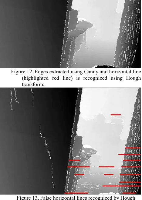
Break-line recognition and removal is last step to increase Kinect data accuracy. To extract edges in image, Canny edge detector (Canny, 1986)is used and to limit result to horizontal edges, a Hough transform (Ballard, 1981) with theta of [-90:-88,88-89] is used. Edges are displayed on Figure 12 and recognized horizontal break-line is highlighted. Though Hough results are acceptable, there is a huge shortcoming that it tends to recognize horizontal lines in scene where there is none (Figure 13). To solve this problem, a simple method of filtering is deployed. Black-White edge image is merged with binary image of Hough lines andifthereisanylineleft,thenit’sareal break-line.
As it was mentioned in explanations, it has to be decided to rectify image or abandon it. Base on experiments, in case that break-line is before 100th row, usually there is no need to rectify
it since there won’t be lots of data lost. Among all database
containing more than thousands of images which was obtained using few hours of different scene imaging, there was not a single frame with break-line after its 250th row which is middle of image though more than 90% of them had break-line before their 100th row.
Anyway, in case we need to determine shift value and rectify image, the proposed solution use the same edge image acquired previously. Then a Hough transform is applied to extract
vertical or near vertical lines in upper half of image. If number of lines in upper and lower part of break-line is equal, then shift value can be calculated using difference between beginning and end of lines. Another problem raise here when most of the time Hough transform result, on near vertical line extraction is not acceptable and reliable.
Thoughit’spossibletodevelopanalgorithmtodealwiththis
problem, given the fact that just 1/5th of image is lost, partial image removal (in case of before 100th row) and image breaking (in case of near middle of image) seems suitable solutions.
4. CONCLUSIONS
Kinect and similar low-cost imaging systems are increasing in quantity and quality among different users. 3D modelling is no longer limited to users of computer vision and other similar professional fields. Range data provided by these systems still lack in sense of accuracy compared to industrial sensors so some pre-processing steps are proposed to increase precision and accuracy of this data. The first one is Neighbourhood of Null pixels that adds an attribute of accuracy to data and can be used for further process of point-cloud registration and boundary determination. This one is simplest and most effective if edge extraction is required. Next one is polynomial fitting which recognizes surfaces in a series of images and track them. Also in case of flat surfaces, in final stage of modelling instead of using discrete values of range image use a fitted surface. Surface recognition and tracking is required and due to its complexity some specific applications such as 3D reconstruction are recommended to use this process. Finally, there are Break-lines which are errors made in transferring step and cause a horizontal shift in image. Using this known fact that this error always occurs horizontally, they can be recognized and dependant on case they can be rectified, partially removed or split.
Figure 12.Edges extracted using Canny and horizontal line (highlighted red line) is recognized using Hough transform.
Figure 13.False horizontal lines recognized by Hough transform.
References
Ballard, D.H., 1981. Generalizing the Hough transform to detect arbitrary shapes. Pattern recognition 13, 111–122.
Canny, J., 1986. A computational approach to edge detection. IEEE transactions on pattern analysis and machine intelligence 8, 679–98.
Chen, W., Chang, Y., Lin, S., Ding, L., Chen, L., 2005. Efficient Depth Image Based Rendering with Edge Dependent Depth Filter and Interpolation. 2005 IEEE International Conference on Multimedia and Expo 1314–1317.
Code Laboratories, CLNUI SDK and drivers, 2011. http://codelaboratories.com/nui
Fraser, C.S., 1997. Digital camera self-callibration. ISPRS Journal of Photogrammetry and Remote Sensing 52, 149–159.
Izadi, S., Kim, D., Hilliges, O., Molyneaux, D., Newcombe, R., Kohli, P., Shotton, J., Hodges, S., Freeman, D., Davison, A., 2011. KinectFusion: real-time 3D reconstruction and interaction using a moving depth camera, in: Proceedings of the 24th
Annual ACM Symposium on User Interface Software and Technology. ACM, pp. 559–568.
Kien, D.T., 2005. A Review of 3D Reconstruction from Video Sequences MediaMill3D technical reports series. ISIS technical report series.
Kinect for Windows, 2013. Microsoft.
http://www.microsoft.com/en-us/kinectforwindows/
Liu, X., Yang, X., Zhang, H., 2011. Fusion of depth maps based on confidence. 2011 International Conference on Electronics, Communications and Control (ICECC) 2658–2661.
Marbelar, 2013. Sofa. http://www.turbosquid.com/3d-models/3d-model-sofa-wood/599243
Matyunin, S., Vatolin, D., Berdnikov, Y., Smirnov, M., 2011. Temporal filtering for depth maps generated by Kinect depth camera. 3DTV Conference: The True Vision-Capture, Transmission and Display of 3D Video, 2011 1–4.
Monster GT 4.6 Roll Cage [WWW Document], 2013. URL http://www.vgracing.com/mm5/merchant.mvc?Store_Code=VG
DEV&Screen=PROD&Category_Code=Roll_Cages&Product_ Code=VGR-MGT_4-6_Chrome
OpenCV, 2013. http://opencv.org/
Staranowicz, A., Mariottini, G.-L., 2012. A comparative study of calibration methods for Kinect-style cameras, in: 5th International Conference on PErvasive Technologies Related to Assistive Environments -PETRA. ACM Press, New York, New York, USA, pp. 1–4.
Victor, Z., 2013. Luxury leather armchair and red curtain above interior (3D). http://www.shutterstock.com/pic-34743001/stock- photo-luxury-leather-armchair-and-red-curtain-above-interior-d.html
Xtion PRO. 2013. ASUS. URL
http://www.asus.com/Multimedia/Xtion_PRO/