Available online at
http://www.iaeme.com/IJMET/issues.asp?JType=IJMET&VType=7&IType=3 Journal Impact Factor (2016): 9.2286 (Calculated by GISI) www.jifactor.com ISSN Print: 0976-6340 and ISSN Online: 0976-6359
© IAEME Publication
MODERN RAPID 3D PRINTER - A DESIGN
REVIEW
T. Prabhu
Assistant Professor, Department of Mechanical Engineering, Rathinam Technical Campus, Echanari,
Coimbatore–641021
ABSTRACT
3D printing is called as additive manufacturing technology where a three dimensional object is created by laying down successive layers of material. It is also known as rapid prototyping, is a mechanized method whereby 3D objects are quickly made on a reasonably sized machine connected to a computer containing blueprints for the object. It is working under the principle of Fused Deposition Modelling (FDM). The 3D printing concept of custom manufacturing is exciting to nearly everyone. The basic principles include materials cartridges, flexibility of output, and translation of code into a visible pattern.3D Printers are the machines that produce physical 3D models from digital data by printing layer by layer. It can make physical models of objects either designed with a CAD program or scanned with a 3D Scanner. Here we are going to propose a model report on design and fabrication of a 3D printer.
Key words: 3D Printer, Additive Manufacturing, FDM, 3D Scanner.
Cite this Article: T. Prabhu. Modern Rapid 3D Printer - A Design Review.
International Journal of Mechanical Engineering and Technology, 7(3), 2016, pp. 29–37.
http://www.iaeme.com/currentissue.asp?JType=IJMET&VType=7&IType=3
INTRODUCTION
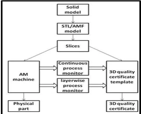
3D printing or additive manufacturing is a process of making three dimensional solid objects from a digital file. The creation of a 3D printed object is achieved using additive processes. In an additive process an object is created by laying down successive layers of material until the entire object is created. Each of these layers can be seen as a thinly sliced horizontal cross-section of the eventual object.
scanner (to copy an existing object). A 3D scanner makes a 3D digital copy of an object.
To prepare a digital file for printing, the 3D modeling software “slices” the final model into hundreds or thousands of horizontal layers. When the sliced file is uploaded in a 3D printer, the object can be created layer by layer. The 3D printer reads every slice (or 2D image) and creates the object, blending each layer with hardly any visible sign of the layers, with as a result the three dimensional object.
OBJECTIVE
1. To implement additive manufacturing 2. To increase the rapid prototyping technology 3. To design and manufacture simple 3D printer 4. To provide low cost 3D printer to the society 5. To make 3D printer as a domestic product
6. To reduce the casting process and time in industries.
ADDITIVE MANUFACTURING
Additive manufacturing is the official industry standard term (ASTM F2792) for all applications of the technology. It is defined as the process of joining materials to make objects from 3D model data, usually layer upon layer, as opposed to subtractive manufacturing methodologies. Synonyms are additive fabrication, additive processes, additive techniques, additive layer manufacturing, layer manufacturing, and freeform fabrication.
Figure 1 Additive Manufacturing
Table 1 Different between Subtractive and Additive manufacturing:
SUBTRACTIVE MANUFACTURING ADDITIVE MANUFACTURING
It is also called as machining process It is also called as 3D printing.
Take a block of material and carve it out Take a block of material and melt it out
Generate 3D model Generate 3D model
Generate CNC program Software slices the 3D model into thin slices
Machine away unwanted material Machine builds it layer by layer
If possible, recycle waste No waste produce
Uncovering a form Creating a form
Less efficient More Efficient
Take more time Take less time
Replacement for manual machining process Replacement for casting process
Example: CNC Machines Example: 3D printers
Fig. Shows about this Fig. Shows about this
Types of Additive Manufacturing Robo casting or Direct Ink Writing (DIW)
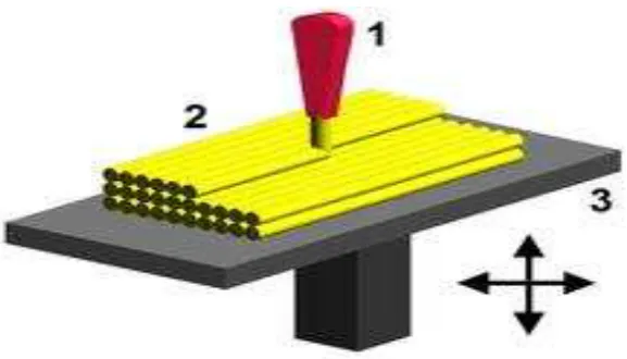
Fused Deposition Modelling
Figure 1 Fused deposition Modelling
SPECIFICTION
Plastic Parts – 26
Shafts- 14Nos - AISI 430 grade rod
Shaft type- Threaded and smooth
Frame- 12mm - plywood
Printing Size- 200mm x 200mm x 270mm
Motor- 5 x Nema 17 - stepper motor
Frame manufacturing- Basic wood tools
Bill of Materials- 193 Nuts, Screws and Washers
Rapid Prototype Parts
Part Name Quantity Design
Z-Axis Top 1
Z-Axis Bottom 1
Y- Axis Motor mount 1
Y-Axis Idler 1
Y- Axis Corner 4
Y- Axis Belt holder 1
X- Axis End Motor
Holder 1
X- Axis End Idler 1
X- Axis Carriage 1
Stepper Motor
Nema 17 – 200 steps per revolution, 1.8 degrees Coil #1: Red & Yellow wire pair.
Coil #2 Green & Brown/Gray wire pair. Bipolar stepper requires 2 full H-bridges! 4-wire, 12 inch leads
42mm/1.65"square body
31mm/1.22" square mounting holes, 3mm metric screws (M3) 5mm diameter drive shaft, 24mm long, with a machined flat
12V rated voltage (you can drive it at a lower voltage, but the torque will drop) at 350mA max current
28 oz*in, 20 N*cm, 2 Kg*cm holding torque per phase 35 ohms per winding
Machine Assembly
Individual components and parts of this model are designed and each of them is assembled according to the axis.
X Axis Assembly
Z- Axis assembly
Final Design 3D view
All components and axis are assembled together. Finally the model is designed with required dimension.
Left Side View Right Side View
Front View Back View
WORKING
Fused deposition modeling (FDM) is anadditive manufacturingtechnology commonly used for modeling, prototyping, and production applications. It is one of the techniques used for3D printing.
FDM works on an "additive" principle by laying down material in layers; a plastic filament or metal wire is unwound from a coil and supplies material to produce a part.
PROCESS
FDM begins with a software process which processes anSTL file (stereo lithography file format), mathematically slicing and orienting the model for the build process. If required, support structures may be generated. The machine may dispense multiple materials to achieve different goals: For example, one may use one material to build up the model and use another as a soluble support structure,or one could use multiple colors of the same type of thermoplastic on the same model.
A plastic filament or metal wire is unwound from a coil and supplies material to anextrusion nozzlewhich can turn the flow on and off. There is typically a worm-drive that pushes the filament into the nozzle at a controlled rate.
The nozzle is heated to melt the material. The thermoplastics are heated past theirglass transitiontemperature and are then deposited by an extrusion head.
The nozzle can be moved in both horizontal and vertical directions by a numerically controlled mechanism. The nozzle follows a tool-path controlled by acomputer-aided manufacturing(CAM) software package, and the part is built from the bottom up, one layer at a time.Stepper motorsorservo motorsare typically employed to move the extrusion head. The mechanism used is often an X-Y-Z rectilinear design, although other mechanical designs such as deltabothave been employed.
Although as a printing technology FDM is very flexible, and it is capable of dealing with small overhangs by the support from lower layers, FDM generally has some restrictions on the slope of the overhang, and cannot produce unsupportedstalactites.
Myriad materials are available, such as Acrylonitrile Butadiene Styrene ABS, Polylactic acidPLA, PolycarbonatePC, PolyamidePA, PolystyrenePS, lignin, rubber, among many others, with different trade-offs between strength and temperature properties. Recently a German company demonstrated for the first time the technical possibility of processing granularPEEKinto filament form and 3D printing parts from the filament material using FDM-technology.
CONCLUSION
It is generally accepted that 3D printing will be a revolutionary force in manufacturing, whether positive or negative. Despite concerns over counterfeiting, many companies are already using the technology to repeatably produce intricate components, for example in automotive and aerospace manufacturing.
As 3D printers become more affordable, they will inevitably be used for local, small scale manufacturing, largely eliminating supply chains for many types of product. Consumer units for home use will even become feasible, allowing end users to simply download a design for the product they require and print it out.
[8] http://iysn.org/2011/09/17/pushing-boundaries-3-d-printing/
[9] www.journalistsresource.org/wpcontent/uploads/2013/03/3d-printing.pdf [10] Chua C.K. et al., “ Rapid Prototyping: principles and applications” Wiley,2003 [11] Jacobs P.F., Stereolithography and other Rapid Prototyping & Manufacturing
Technologies, McGrawHill ,New york,1996
[12] Maha M. Lashin, Design and Execution of A 3D Printer Using A Pla Filament as A New Application of Arduino. International Journal of Mechanical Engineering and Technology, 5(7), 2014, pp. 171–183.