T
eleoperation systems are used when human plan-ning and decision-making capabilities are needed during robotic remote operations. To execute meaningful tasks remotely, the operator has to be able to simultaneously control multiple degrees of freedom (DoFs) of the slave robot and efficiently receive in-formation from the remote site. In these cases, haptic feedback has been shown to improve the operator’s task execution per-formance [1].The potential applications of teleoperation systems are in areas as diverse as the remote handling of hazardous materials
[2], underwater maintenance and repairing tasks [3], and space exploration scenarios [4]. In all of these applications, the tasks occur in a remote location at which, due to accessibility, cost, and/or safety reasons, a robotic system is better suited to operate than a human.
In many cases, the remote teleoperation of robot manipu-lators is done using joystick interfaces and multiple screens with complex user interfaces [5]. These types of systems are not intuitive, and many training hours are required for an op-erator to achieve a reasonable performance level. In this scope, a system composed of a wearable haptic device, combined with a single touch-screen user interface, can provide a much more intuitive interface for the user to teleoperate full remote robotic systems. In particular, when the system is to be used in space teleoperation, the device must be light and portable such that it can be easily worn and adapted to differential operation-al scenarios.
The currently exist-ing state-of-the-art haptic master devices with humanlike workspaces, such as the ViSHaRD10 [6] or the German Aerospace Center (DLR) bimanual interface [7], are based on heavy robotic manipula-tors, which are not wearable and are not easily portable. A haptic exoskeleton for interaction with virtual environments was present-ed in [8]; however, the device is also not portable and is limited to 5 DoFs. Both the sensoric arm master (SAM) [9] and X-Arm2 [10] haptic exoskeletons for teleoper-ation were developed under the scope of European Space Agency programs. While the mechanics of both devices are
Date of publication: 13 November 2014
Bilateral Robot
Teleoperation
Bilateral Robot
Teleoperation
A Wearable Arm Exoskeleton
Featuring an Intuitive User Interface
By João Rebelo, Thomas Sednaoui, Emiel Boudewijn den Exter, Thomas Krueger, and André Schiele
Date of publication:
lightweight, the portability is limited by the lack of body or-thosis and dependence on desktop computers and large ex-ternal hardware for control of the system. Other types of exoskeletons have been presented in the literature for differ-ent applications such as power augmdiffer-entation [11], which fo-cuses on allowing the user to transport heavy loads rather than on accurate force rendering or rehabilitation [12], where the goal is typically to allow the user to exercise cer-tain joints for physical recovery. This distinct set of require-ments makes these types of exoskeletons unsuitable for teleoperation. A recent review of different upper-limb exo-skeleton devices can be found, for example, in [13].
In terms of performance, it was shown in [14] that perfect transparency in 1 DoF can be achieved using a four-channel control architecture. The devices presented in [8] and [9] have shown good capabilities for rendering virtual environments; however, no performance while controlling the robotic ma-nipulators was reported. The position-force architecture using the ViSHaRD10 [6] to control a 7-DoF manipulator allows for executing a stiffness discrimination and screwing task in teleoperation; however, a low level of transparency, which is typical in this architecture, is reported in the results.
It is the goal of this article to develop a complete end-to-end teleoperation system using the modified SAM exoskel-eton as a haptic master device to control a 7-DoF Kuka lightweight robot (LWR) with transparent force reflection to the operator. The new master implementation allows, for the first time, a completely portable wearable master exo-skeleton featuring an intuitive user interface in terms of robot control and system operation. A Cartesian multiple-DoF four-channel architecture [14], which provides a high level of transparency to the operator, is implemented and validated using the setup. This system can be used to per-form generic teleoperation tasks and provides a first step toward a technology demonstration experiment that will be carried out onboard the International Space Station in the coming years [4]. While the system used is very specific, the discussion aims to be as generic as possible regarding the implementation of multiple-DoF bilateral teleoperators using wearable haptic master devices.
System Architecture
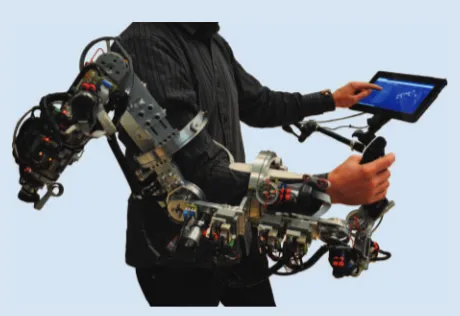
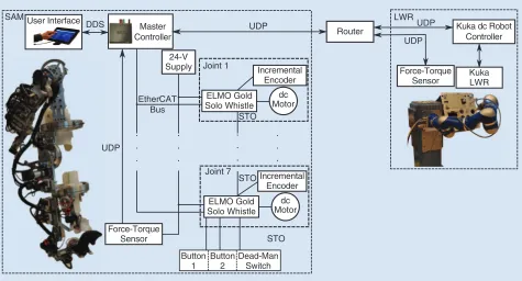
The bilateral teleoperation system presented in this article consists of a 7-DoF exoskeleton arm master used by a human operator to control a 7-DoF slave robot. The local joint con-trol of the master device is implemented using distributed servo drives that communicate by using a state-of-the-art EtherCAT network, while the communication between the master and slave devices is achieved with user datagram pro-tocol (UDP) communication. The high-level control of the system by the operator is performed via a Web-based graphi-cal user interface (GUI) on a tablet computer, which commu-nicates with the remaining components of the system using the data distribution service (DDS) communication middle-ware. The master device being worn by an operator is shown in Figure 1, with the system architecture shown in Figure 2.
The remainder of this section explains each of the compo-nents in this architecture in detail.
Sensoric Arm Master
Exoskeleton
The SAM [9] is a serial kinematics exoskeleton, isomorphic to the human arm. It has 7 DoFs from the shoulder to the wrist, as shown in Figure 3. The link lengths between joints 3 and 4, joints 5 and 6, and joint 7 and the joystick handle are adaptable using sliding mechanisms, and they have to be adjusted de-pending on the operator dimensions to allow adequate align-ment with the human arm joints. The kinematics have been implemented such that singularities of the mechanism are placed outside the human operator’s reachable workspace. All of the joints are actuated using a combination of dc motors and capstan gears for low
friction and backdrivabili-ty. The joint torques were initially designed to be 1/20th of maximum human torque with addi-tional torque included in joints 3 and 5 to allow for friction compensation of the open bearings. Given the fact that only com-mercially available dc mo-tors are used and the gear ratio limitations, these torques do not exactly correspond to the design target. Table 1 gives a
summary of the actual exoskeleton torques and the typical and maximum human torques for each joint. More details on the mechanical design of the device can be found in [9].
Every joint is equipped with an incremental encoder and is current-controlled using commercially available ELMO servo drives. The exoskeleton control algorithms are executed on a master control PC, and the communication with the
Making use of the
EtherCAT bus enables
the high-performance
haptic master to have a
modular architecture with
a very small distributed
hardware footprint.
individual ELMO drives installed throughout the arm is done via an EtherCAT communication bus [16]. Each of the seven EtherCAT slaves has a local current-control loop, which is driven by the EtherCAT bus. The communication runs over the Ethernet physical medium, implementing a specific sum-mation process and logical addressing system that optimizes the bandwidth usage and ensures real-time communication. The architecture requires a master device, which addresses the slaves in the network. The implementation of the EtherCAT master used in this article is based on the open-source simple open Ethercat master [17] for its low-level pro-tocols and runs on any computer with the Linux operating system. Additionally, the protocol provides a means for using a distributed clock, which ensures that all of the devices in the bus run in a synchronous manner.
To measure the end-effector force and torques between the operator and exoskeleton, an ATI Gamma 6-DoF force-torque sensor with a resolution of 0.01 N and 0.0005 Nm is mounted at the base of the joystick handle. The force-torque sensor readouts are sampled via UDP at the same frequency as the EtherCAT network.
As a safety mechanism, a dead-man switch is present on the operator joystick, and the drive electronics hardware is only en-abled when this button is pressed by the user. The safe-to-oper-ate (STO) signal of the ELMO drives is used for this purpose. Two additional multipurpose digital inputs, corresponding to buttons 1 and 2, shown in Figure 2, are available.
To minimize the hardware footprint and keep the system portable, all of the control algorithms and the EtherCAT mas-ter are executed on a FitPC2 (10 # 10 # 3 cm) running
Xenomai real-time Linux. The whole system is powered from
Joint 7 Joint 6
Upper-Body Orthosis Joint 5
Joint 4 Joint 3
Joint 2 Joint 1
Figure 3. The SAM joint configuration and upper-body orthosis.
Table 1. The SAM joint torque output.
Joint
SAM Con-tinuous/Stall Torque (Nm)
Typical Human Torque in Daily Life (Nm) [15]
Maximum Hu-man Arm Torque (Nm) [15]
1 4.4/19.7 10 134
2 4.4/19.7 9.6 115
3 6/27 3.1 60
4 3.6/16.4 3.8 72
5 2.2/7.7 0.4 9
6 0.4/1.7 0.38 21
7 0.4/1.7 0.25 20
SAM User Interface
Master Controller DDS
24-V Supply
UDP
UDP
STO STO
Joint 1 Incremental Encoder ELMO Gold
Solo Whistle dc Motor
Joint 7
Incremental Encoder ELMO Gold
Solo Whistle STO Button
1
Button 2
Dead-Man Switch
dc Motor EtherCAT
Bus
UDP UDP LWR
Kuka dc Robot Controller
Kuka LWR Router
Force-Torque Sensor
Force-Torque Sensor
a lithium polymer battery pack. Using this configuration, a maximum achievable control bandwidth of 1 kHz was reached over the full exoskeleton system. The same embed-ded PC is also used to handle the connection to the LWR through UDP and the DDS interface to the GUI.
Graphical User Interface
The high-level system state control and user interaction is done using a GUI on a touch screen. For the implementation, a state-of-the-art cross-platform approach using HTML, CSS, and JavaScript has been chosen. Using these languages, the GUI can be ported to any platform that has a compatible Web browser or even converted to a native app. The data commu-nication between the master controller and the GUI is done using the DDS communication middleware [18]. The mid-dleware provides a loosely coupled data-centric publisher-subscriber system featuring a broad number of quality-of- service (QoS) settings. To define the data that are published or subscribed, only a single data interface file needs to be created by the developers. The middleware takes care of all the con-nectivity and delivery within different networks and eases the development and portability as well as the possibility to ex-tend the system by connecting other devices.
The GUI runs on a tablet computer, which the user can operate while wearing the exoskeleton. This means that all controls are accessible during operation. The interface is cur-rently used for initial joint calibration and for starting and stopping the teleoperation. Since DDS messages cannot cur-rently be read directly by Javascript, a custom-made DDS/ Websocket bridge runs on a machine in the same network. This bridge reduces the maximum data update rate to approx-imately 40–60 Hz, which is nonetheless sufficient for typical GUI purposes. Figure 4 shows an example of the user inter-face screen during operation.
Upper-Body Orthosis
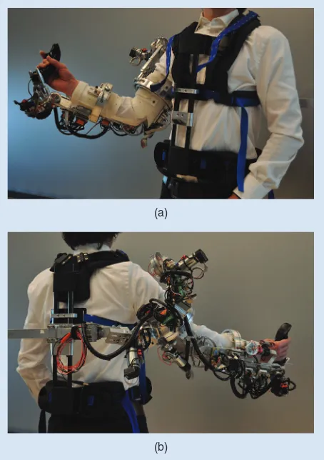
To make the exoskeleton portable, a dedicated upper-body orthosis was built. The design consists of a vest that can be strapped to the operator’s body to transfer load away from the arm and onto the body. During development, static and dy-namic anthropometric factors were considered to ensure a close and comfortable fit to operators of different statures and body sizes. In addition, the vest includes design features pres-ent in most mountaineering backpacks to ensure optimal load transfer to the hips of the operator.
Figure 5 shows the prototype of the vest with the SAM exoskeleton mounted to the back. On the front and back of the vest, a telescopic frame was implemented to provide ad-justability to fit different operator statures in addition to being a generic mounting interface for exoskeletons.
Kuka LWR
The LWR, used as the slave device in this setup, is a commer-cially available 7-DoF LWR, which can be used directly in an impedance-controlled mode. The Cartesian impedance can be configured in values ranging, approximately, from 500 to
2,000 N/m for translations and 10 Nm/c and 500 Nm/c for ro-tations. The damping can be configured at joint level between 0.1 and 2 Nm : rad-1: s. An ATI Gamma 6-DoF force-torque
sensor with a resolution of 0.01 N and 0.0005 Nm is mounted on the robot tool to measure the actual contact forces and torques. Both the master and slave force-torque sensor are set
Record Waypoint Video View
Replay Waypoint
Ready for Next
Record Trajectory
Replay Trajectory
Guidance On
Guidance Off
Figure 4. The GUI during the operation phase. The GUI provides the remote site video feed to the operator as well as additional information on the master and slave status and access to all the high-level control of the system.
(a)
(b)
to zero when operation is started. The manipulator is con-trolled using the Kuka fast research interface (FRI) [19] at a frequency of 1 kHz. Using this interface, it is possible to con-trol both the tool Cartesian pose and forces/torques as well as the stiffness and damping of the robot.
Control Architecture
The control architecture describes the control structure of the bilateral teleoperation system. The first part gives a brief de-scription of the Cartesian mapping between the master and slave devices, and the second part describes the four-channel bilateral control architecture.
Master/Slave Mapping
In typical teleoperation scenarios, two types of mapping be-tween the master device and slave robots are used: either in-dexed, i.e., the operator moves to an arbitrary position and the control starts relative to this initial point, or absolute, in
which the master and slave devices are aligned before starting the operation according to a predefined mapping.
In this article, a 6-DoF indexed Cartesian mapping between the master and slave device is used. The end-effector pose of the master device is computed using its forward kinematics, and the difference between the actual and start pose is comput-ed and convertcomput-ed to a pose command to the LWR. There is no scaling between the measured and commanded motion, i.e., a 1-cm motion at the master side corresponds to a 1-cm motion command at the slave side. Figure 6 shows a typical initial con-figuration mapping and reference frames for both the master and slave. Given the orientation of the two devices and the camera image angle, the x, y, and z axis of the SAM are mapped to the x, z, and y axis of the LWR, respectively. This transformation corresponds to a rotation, which can be defined in a matrix format as
.
Four-Channel Bilateral Teleoperation Control
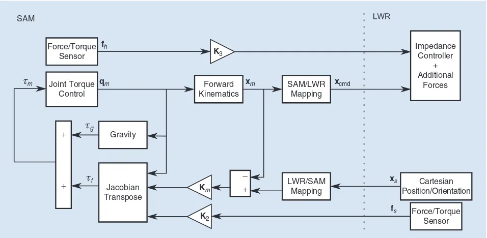
Bilateral teleoperation control is done using the four-channel architecture [14] implemented for all of the Cartesian DoFs of the system. Using this architecture, the master sends both the position commands and the actual force that the operator is exerting to the impedance-controlled slave manipulator. The measured force and position of the slave manipulator are sent back to the master device and used to compute the amount of force that is transmitted to the operator. Additionally, the weight of the master device felt by the operator can be reduced by a gravity compensation algorithm. The complete teleopera-tion control architecture is shown in Figure 7.
X
Figure 6. The master–slave initial mapping and reference frames. The LWR world frame is not explicitly shown since all the motion happens relative to the initial tool frame. The x, y, and z axis of the SAM are mapped to the x, z, and y axis of the LWR, respectively.
Figure 7. The teleoperation four-channel control architecture.
The master joint torques resulting from the force-feedback commands can be calculated at each instant using the principle of virtual work as
( ) [ ( ( )) ( )
where xf is the master-commanded
joint torque vector, K2 is the master
force channel diagonal gain matrix, fs is
the force- torque vector measured by the force-torque sensor mounted on the slave device, Km is the master position
channel diagonal gain matrix, xs is the
actual slave manipulator position, and
xm is the actual master position, which
corresponds to the slave manipulator reference. The gravity compensation al-gorithm is implemented to compute the torque caused by gravity on each link i
as detailed in, for example, [20].
On the slave side, both the stiffness
Ks and damping Bs of the
manipula-tor can be configured independently in each Cartesian direction using the FRI interface. The joint torque com-mands in the slave manipulator are computed as
where xs is the slave-commanded joint
torque vector, Ks is the slave Cartesian
stiffness diagonal matrix, K3 is the
slave force channel diagonal gain ma-trix, and fm is the force-torque vector
measured by the force-torque sensor mounted on the slave device. The LWR controller internally compensates for gravity, friction, and other dynamic
ef-fects of the manipulator; however, since the user has no con-trol over these parameters, they are explicitly left out of the computation.
Following the tuning rules given in [14], using this con-trol architecture and making K2=K3=I is expected to
provide the user with perfect contact transparency. However, in this case, since the joint friction and other dynamic effects of the master device are not compensated, the operator will feel additional force in free air, which deviates from perfect transparency in this condition.
Bilateral Teleoperation Performance
Bilateral teleoperation performance shows the performance of the complete bilateral teleoperation system when using the SAM exoskeleton to command the LWR, both in free air and contact. In the presented experimental scenario, the operator is instructed to drive the slave manipulator into contact with three surfaces with different stiffnesses, keeping the contact with it for a couple of seconds. The surfaces are a soft foam, hard foam, and rigid metal plate. This is a typical stiffness dis-crimination task, which is common in many teleoperation
5 10 15 20 25 30 35
LWR Commanded Position LWR Actual Position
(a)
LWR Measured SAM Measured SAM Commanded
(b)
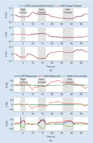
Figure 8. The master–slave (a) positions and (b) force behavior during the stiffness discrimination task with Ks=1 000, N/m, Bs=0 7. N$m-1$s,Km=150N/ ,m and
scenarios. To facilitate the analysis, the results presented cor-respond only to Cartesian positions. Since rotational motion is not required to execute this task, they are not commanded and their stiffness setting is kept at a maximum to prevent motion. Nonetheless, end-effector rotations can also be con-trolled by the setup with a motion and force behavior similar to that of the Cartesian positions.
Figure 8 shows the Cartesian position and force performance of the system in bilateral teleoperation with Ks=1 000, N/m, Bs=0 7. N/m, Km=150N/m, and K2=K3=1 with all
values identical in every Cartesian direction and 30% gravity compensation. The parameters were tuned following the trans-parency rules detailed in the “Control Architecture” section. Additionally, the position channel gains were chosen such that a satisfactory position tracking behavior of the slave was achieved. The plotted forces correspond to the commanded and force/ torque sensor measurements at the master and to the force/ torque sensor measurements at the slave.
As shown in Figure 8, the robot manipulator follows the master trajectory in each Cartesian direction with negligible errors. In free-air motion, even though there are no forc-es commanded to the operator, the interaction force mea-sured at the master has a value of up to 10 N in the x
direction and 5 N in both the y and z directions.
The contacts with the rigid, hard, and soft surfaces occur in the z direction between 3 and 6 s, 12 and 16 s, and 25 and 31 s, respectively. In both the rigid and the hard contact, the forces rendered to the operator accurately follow those measured at the slave end-effector. In the soft contact, there is a deviation of approximately 2 N between the force rendered to the operator and the force exerted by the slave on its environment. At the impact between the slave and rigid surface (t=3s), a force peak of more than 10 N occurs, which is not transmitted to the operator. Throughout the entire operation, the system is stable, showing no oscillations and no involuntary losses of contact.
Table 2 shows the actual and rendered stiffness for each of the surfaces, estimated from the position and force data of the master and slave, respectively. The rigidity of the surface ren-dered to the operator is one order of magnitude smaller than that of the actual surface, whereas the hard and soft surfaces have very approximate values.
Discussion
In this section, the system implementation and the control advantages and disadvantages are discussed in regard to de-sign decisions and possible future improvements.
System Implementation
The system hardware presented is a fully integrated solution for a portable bilateral teleoperation workstation. The devel-oped orthosis is of particular importance since it allows the user to carry the whole mass of the exoskeleton (approximate-ly 7 kg) in a backpack-like fashion. During tests, in which sev-eral operators carried the exoskeleton on their body, many positive reactions were observed and demonstrated the feasi-bility of a comfortable portable exoskeleton.
Using the EtherCAT protocol allowed reaching high-per-formance control bandwidths while keeping a reduced hard-ware size and weight. The downside of the protocol is its complexity, especially the fact that each slave in the network needs to be configured individually at start-up and multiple algorithms are necessary on the master to handle the distrib-uted clock of the system.
Having the GUI running on a tablet allows the user to view the video feed and execute high-level control of the sys-tem (e.g., start/stop commands or online parameter adapta-tion) while still being able to control the robot using the exoskeleton. The multiplatform nature of the interface and the use of DDS is also advantageous since the GUI can easily be deployed on other machines, thus allowing easy reconfigura-tion of the system according to the operareconfigura-tion needs.
Two fundamentally different communication approaches exist intentionally within the system. A message-centric ap-proach using UDP is implemented for the master–slave com-munication that takes place in real time, whereas a data-centric approach has been chosen for the GUI for its flex-ibility and easy reconfiguration. In the future, DDS, with its multiple QoS options, can also be used on real-time links.
Teleoperation Control and Performance
From the system performance results presented in the “Bilateral Teleoperation Performance” section, it can be seen that using the four-channel architecture with the SAM exo-skeleton controlling the LWR in impedance-control mode achieves a high level of transparency in both free air and con-tact. The stiffness rendered to the operator for different sur-faces allows a clear distinction to be felt between them.
An analysis of the impact with rigid contact is shown in Figure 8 at t=3s, and it can be observed that the high-fre-quency components of the force are not transmitted to the operator. Nonetheless, the transition between free air and contact feels very crisp and is clearly distinguishable from the transition between free air and hard contact.
In free-air motion, the dynamics of the master device are felt by the operator, particularly the effects of gravity and fric-tion in the joints. Given the mass of the device, the used dc motors are not able to fully compensate for gravity while still having enough power to generate force feedback to the opera-tor. With 30% gravity compensation, the user can operate the device more comfortably while the motors can still provide sufficient torque for accurate force-feedback rendering. Since the force/torque sensors are reset to zero at the start of the op-eration, to prevent the uncompensated effects of gravity on
Table 2. The comparison between the actual and rendered stiffness for different surfaces.
Surface Actual (N/m) Rendered (N/m)
Rigid 5 2 10. 5
$ 4 5 10. $ 4
Hard 4,910 4,620
the master side to be transmitted to the slave, these effects are not visible in the measured SAM forces. The forces caused by friction are always below 10 N and are, therefore, causing little effect to the operator. It was shown in [9] that these values could be further reduced using model-based compensation.
As shown in Figure 8, the commanded forces are not exact-ly rendered to the operator, which is expected given the open-loop nature of the controller. Nonetheless, the stiffness rendered to the operator has enough accuracy to clearly distin-guish between the different types of contact. The effects of dif-ferent controllers with local force and torque control loops should be studied in the future. Additionally, how the accuracy of the environment rendered to the operator affects task per-formance is a continuous research question in the field. This system provides the means to investigate this in more depth.
Conclusions
The system presented in this article allows 6-DoF bilateral teleoperation with a high level of transparency. Using the SAM haptic device as the controller for the Kuka LWR in im-pedance mode, with a system control frequency of 1 kHz, contact with surfaces of different stiffnesses can be accurately rendered to the operator.
Making use of the EtherCAT bus enables the high-perfor-mance haptic master to have a modular architecture with a very small distributed hardware footprint. This modular de-sign, combined with the adjustable body orthosis and the tab-let interface, makes the SAM workstation a fully portable teleoperation master with a humanlike workspace.
Acknowledgments
This work was partially supported by the Portuguese FundaÇão para a Ciência e Tecnologia under the doctoral grant SFRH/BD/69564/2010. We would like to acknowledge Manuel Aiple for implementing the DDS/Websocket bridge.
References
[1] T. B. Sheridan, Telerobotics, Automation and Human Supervisory Control.
Cambridge, MA: MIT Press, 1992.
[2] G. Clement, J. Vertut, R. Fournier, B. Espiau, and G. Andre, “An overview
of CAT control in nuclear services,” in Proc. IEEE Int. Conf. Robotics
Automation, 1985, vol. 2, pp. 713–718.
[3] D. Yoerger and J.-J. Slotine, “Supervisory control architecture for
underwa-ter teleoperation,” in Proc. IEEE Int. Conf. Robotics Automation, 1987, vol. 4,
pp. 2068–2073.
[4] A. Schiele, “METERON—Validating orbit-to-ground telerobotics
opera-tions technologies,” in Proc. 11th Symp. Advanced Space Technologies Robotics
Automation, 2011.
[5] V. Abbasi, B. Azria, E. Tabarah, V. Menon, and M. Bedirian, “Improved
7-DOF control of ISS robotic manipulators,” in Proc. 8th Int. Conf. Space
Operations, 2004.
[6] A. Peer, B. Stanczyk, and M. Buss, “Haptic telemanipulation with
dissimi-lar kinematics,” in Proc. IEEE/RSJ Int. Conf. Intelligent Robots Systems, 2005,
pp. 3493–3498.
[7] T. Hulin, K. Hertkorn, P. Kremer, S. Schatzle, J. Artigas, M. Sagardia, F. Zacharias, and C. Preusche, “The DLR bimanual haptic device with optimized
workspace,” in Proc. IEEE Int. Conf. Robotics Automation, 2011, pp.
3441–3442.
[8] L. I. Lugo-Villeda, A. Frisoli, S. Pabon, M. A. Padilla, E. Sotgiu, and M. Bergamasco, “Light-exoskeleton and data-glove integration for enhancing
vir-tual reality applications,” in Proc. Int. Conf. Advanced Robotics, 2009, pp. 1–6.
[9] P. Letier, M. Avraam, S. Veillerette, M. Horodinca, M. de Bartolomei, A. Schiele, and A. Preumont, “SAM: A 7-DOF portable arm exoskeleton with
local joint control,” in Proc. IEEE/RSJ Int. Conf. Intelligent Robots Systems,
2008, pp. 3501–3506.
[10] A. Schiele and G. Hirzinger, “A new generation of ergonomic exoskele-tons—The high-performance X-Arm-2 for space robotics telepresence,” in
Proc. IEEE/RSJ Int. Conf. Intelligent Robots Systems, 2011, pp. 2158–2165.
[11] H. Kazerooni, “Exoskeletons for human power augmentation,” in Proc.
IEEE/RSJ Int. Conf. Intelligent Robots Systems, 2005, pp. 3459–3464.
[12] H. S. Lo and S. Q. Xie, “Exoskeleton robots for upper-limb rehabilitation:
State of the art and future prospects,” Med. Eng. Phys., vol. 34, no. 3, pp. 261–
268, 2012.
[13] R. Gopura, K. Kiguchi, and D. Bandara, “A brief review on upper
extremi-ty robotic exoskeleton systems,” in Proc. 6th IEEE Int. Conf. Industrial
Information Systems, 2011, pp. 346–351.
[14] D. A. Lawrence, “Stability and transparency in bilateral teleoperation,”
IEEE Trans. Robot. Automat., vol. 9, no. 5, pp. 624–637, 1993.
[15] C. Carignan, M. Liszka, and S. Roderick, “Design of an arm exoskeleton
with scapula motion for shoulder rehabilitation,” in Proc. IEEE 12th Int. Conf.
Advanced Robotics, 2005, pp. 524–531.
[16] D. Jansen and H. Buttner, “Real-time Ethernet: The EtherCAT solution,”
Comput. Control Eng., vol. 15, no. 1, pp. 16–21, 2004.
[17] (2014, Feb.). Simple open EtherCAT master. [Online]. Available: http:// soem.berlios.de/
[18] G. Pardo-Castellote, “OMG data-distribution service: Architectural
over-view,” in Proc. 23rd Int. Conf. Distributed Computing Systems Workshops,
2003, pp. 200–206.
[19] G. Schreiber, A. Stemmer, and R. Bischoff, “The fast research interface for
the KUKA lightweight robot,” in Proc. IEEE Workshop Innovative Robot
Control Architectures Demanding (Research) Applications How to Modify Enhance Commercial Controllers, 2010, pp. 15–21.
[20] L. Sciavicco and B. Siciliano, Modelling and Control of Robot
Manipulators, 2nd ed. Berlin Heidelberg, Germany: Springer-Verlag, 2000, ch. 3, pp. 113–117.
João Rebelo, Delft University of Technology, The Netherlands. E-mail: [email protected], [email protected], and [email protected].
Thomas Sednaoui, STMicroelectronics, The Netherlands. E-mail: [email protected].
Emiel Boudewijn den Exter, ESA Telerobotics and Haptics Lab, The Netherlands. E-mail: [email protected].
Thomas Krueger, European Space Agency, The Netherlands. E-mail: [email protected] and thomas.krueger.home@ googlemail.com.