Principle:
The force acting on a current-carry-ing conductor loop in a uniform magnetic field (Lorentz force) is measured with a balance.
Conductor loops of various sizes are suspended in turn from the balance, and the Lorentz force is determined as a function of the current and magnetic induction. The uniform magnetic field is generated by an electromagnet. The magnetic induct-ion can be varied with the coil cur-rent.
Tasks:
1. The direction of the force is to be determined as a function of the current and the direction of the magnetic field.
2. The force Fis to be measured, as
a function of the current ILin the
conductor loop, with a constant magnetic induction B and for
conductor loops of various sizes. The magnetic induction is to be calculated.
3. The force Fis to be measured, as
a function of the coil current IM,
for a conductor loop. In the range being considered, the magnetic induction B is, with sufficient
ac-curay, proportional to the coil cur-rent IM.
Lorentz force Fas a function of the current ILin the conductor loop.
What you can learn about …
Uniform magnetic field
Amperemeter 1/5 A DC 07038.00 2
Tripod base -PASS- 02002.55 2
Stand tube 02060.00 1
Support rod -PASS-, square, l= 1000 mm 02028.55 1
Right angle clamp -PASS- 02040.55 1
Balance LGN 310, on rod 110 81.01 1
Pole pieces, rectangular, 1 pair 110 81.02 1 1 Wire loop, l= 12.5 mm, n= 1 110 81.05 1 1
Wire loop, l= 25 mm, n= 1 110 81.06 1 1
Wire loop, l= 50 mm, n= 2 110 81.07 1 1
Wire loop, l= 50 mm, n= 1 110 81.08 1 1
Iron core, U-shaped, laminated 06501.00 1 1
Base for iron cores 06508.00 2 2
Coil, 900 turns 06512.01 2 2
Metal strip, with plugs 06410.00 2 2
Distributor 06024.00 1 1
Bridge rectifier, 30 V AC/1 A DC 06031.10 1 1
On/off switch 06034.01 1 1
Power supply, universal 13500.93 1 1
Connecting cord, l= 100 mm, red 07359.01 1 2
Support base, variable 02001.00 1
Boss head 02043.00 2
Support rod,stainl.steel, 1000 mm 02034.00 1
Cobra3 Basic Unit 12150.00 1
Measuring module Newton 12110.00 1
Newton sensor 12110.01 1
Cobra3 Current sensor, 6 A 12126.00 2
PowerGraph Software 14525.61 1
Power supply, 12 V- 12151.99 1
RS232 cable 14602.00 1
PC, Windows® 95 or higher
What you need:
Complete Equipment Set, Manual on CD-ROM included
Current balance / Force acting on a
current-carrying conductor
P24106 01/15
Related topics
Uniform magnetic fields, magnetic induction (formerly mag-netic-flux densitiy), Lorentz force, moving charges, current.
Principle
The force acting on a current-carrying conductor loop in a uni-form magnetic field (Lorentz force) is measured with a balan-ce.
Conductor loops of various sizes are suspended in turn from the balance, and the Lorentz force is determined as a function of the current and magnetic induction. The uniform magnetic field is generated by an electromagnet. The magnetic induct-ion can be varied with the coil current.
Equipment
Current balance 11081.88 1 consisting of
Balance LGN 310, on rod 11081.01 1 Pole pieces, rectangular, 1 pair 11081.02 1 Wire loop, l= 12.5 mm, n= 1 11081.05 1
Wire loop, l= 25 mm, n= 1 11081.06 1 Wire loop, l= 50 mm, n= 2 11081.07 1 Wire loop, l= 50 mm, n= 1 11081.08 1 Iron core, U-shaped, laminated 06501.00 1 Base for iron cores 06508.00 2 Coil, 900 turns 06512.01 2 Metal strip, with plugs 06410.00 2 Distributor 06024.00 1 Bridge rectifier, 30 V AC/1 A DC 06031.10 1 On/off switch 06034.01 1 Power supply, universal 13500.93 1 Ammeter 1/5 A DC 07038.00 2 Tripod base -PASS- 02002.55 2
Stand tube 02060.00 1
Support rod -PASS-, square, l= 1000 mm 02028.55 1 Right angle clamp -PASS- 02040.55 1 Connecting cord, l= 100 mm, red 07359.01 1 Connecting cord, l= 250 mm, black 07360.05 2 Connecting cord, l= 250 mm, blue 07360.04 2 Connecting cord, l= 500 mm, red 07361.01 2 Connecting cord, l= 500 mm, blue 07361.04 1 Connecting cord, l= 1000 mm, red 07363.01 1 Connecting cord, l= 1000 mm, blue 07363.04 1
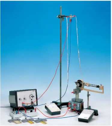
Fig. 1: Experimental set-up: Current balance.
Recommended accessories for measuring the magnetic field : Teslameter, digital 13610.93 1 Hall probe, tangent., prot. cap 13610.02 1
Tasks
1. The direction of the force is to be determined as a function of the current and the direction of the magnetic field.
2. The force Fis to be measured, as a function of the current
ILin the conductor loop, with a constant magnetic
induc-tion B and for conductor loops of various sizes. The magnetic induction is to be calculated.
3. The force Fis to be measured, as a function of the coil cur-rent IM, for a conductor loop. In the range being
consider-ed, the magnetic induction B is, with sufficient accuray, proportional to the coil current IM.
Note
If a magnetic-field measuring instrument is available, then, in the third of the above tasks, the Lorentz force can be meas-ured directly as a function of the magnetic induction.
Set-up and procedure
The experiment is set up as in Fig. 1. The coils of the electro-magnet are connected in series and are connected to the alternating voltage output of the power unit via an ammeter, a switch and a bridge rectifier. For the first two parts of the experiment, a fixed voltage of 12 V a. c. is selected and the associated current IMin the coils is measured.
The conductor loops are connected via two light flexible metal stripes, first of all to a distributor, and then via an ammeter to the direct voltage output of the supply unit. The distance be-tween the metal strips should be as large as possible and they should only sag slightly, so that no forces from the magnetic field act on them.
1. The pole shoes are first placed on the electromagnets in such a way as to produce an air gap of about 4 cm. The con-ductor loop with l = 25 mm is suspended from the balance with its horizontal section perpendicular to the lines of the magnetic field.
The balance is trimmed with no current flowing through the conductor, and a conductor current of IL= 5 A is then set. The
direction and magnitude of the force are determined as a function of the direction of the current and are observed with the magnet rotated about a horizontal axis. Without a magnet-ic field, the position of the balance is observed both with and without current flowing through the conductor loop.
2. The pole shoes are placed on the electromagnet with their edges parallel and with an air gap of 1 cm.
The conductor loop with l= 12.5 mm is hung on the balance. The horizontal section of the conductor runs perpendicular to the field lines and – with the balance trimmed – is in the midd-le of the uniform field (fine adjustment with screw on tripod). The current in the conductor is raised in steps of 0.5 A with the knob on the power unit. The mass moof the conductor loops
is determined with the magnetic field switched off. The magnetic field is then switched on, the (apparently increased) mass m is measured, and the Lorentz force calculated from the difference between the two readings.
The measurement is made in a similar way for the other three conductor loops.
3. The procedure is essentially as described in 2 above, only with conductor loop l= 50 mm, n= 2.
The current in the conductor is IL= 5 A. The current IMin the
coils is varied by means of the applied voltage. The Lorentz force Fon each occasion is determined from the readings.
Theory and evaluation
In a magnetic field with a magnetic induction B씮, a force F씮
(Lorentz force) acts on a moving charge carrier with charge q
and velocity v씮:
F씮= q· (v씮· B씮). (1)
The force vector F씮is perpendicular to the plane occupied by
v씮and B씮. In this experiment v씮and B씮are also at right angles to each other, so that the following relationship holds for the values of the vectors:
F= q· v· B. (2)
The velocity of the charge carriers (electrons) is measured via the electric current ILin the conductor. The total charge of the
electrons in the section of the conductor of length lmust be formulated for q:
q· v= IL· l. (3)
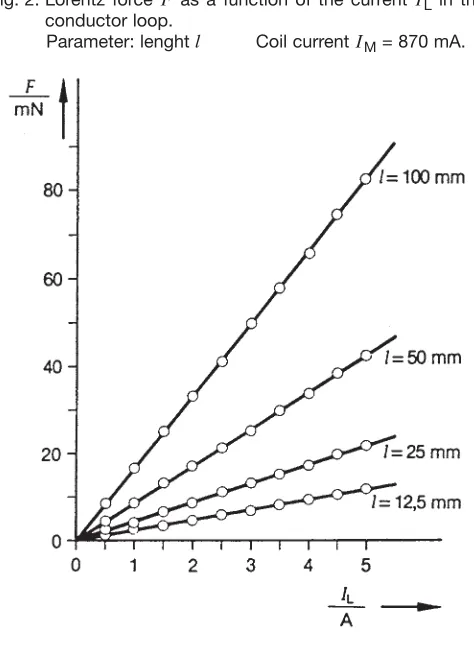
Fig. 2: Lorentz force Fas a function of the current ILin the
conductor loop.
The following is therefore obtained for the Lorentz force:
F= IL· l· B. (4)
1. Observations show that the direction of the force vector is dependent on the direction of travel of the electrons and the direction of the magnetic field.
In the field lines are parallel to the direction of travel, a force acts on the conductor loops. At a magnetic induction of B= 0, the balance changes its position only slightly when the cur-rentIin the conductor loop is switched on. At IL= 5 A,
how-ever, the change in the force is quite measureable. The explantation of this effect is that two conductors carrying a current are mutually attracted. When a current flows, the flex-ible metal strips change their position slightly and can thereby affect the position of the balance.
2. In the two vertical sections of the conductor loop the elec-trons travel in opposite directions, and the two forces acting on them cancel each other out. Only the horizontal section of the conductor loop, whose lenght lis indicated on each occa-sion on the loop, therefore affects the measured Lorentz force. One of the conductor loops has two turns (n= 2), each with a horizontal lenght of 50 mm. The Lorentz force on these con-ductor loops is exactly equivalent to that on a single loop of twice the lenght (l= 100 mm, n= 1).
The experimental results are shown in Fig. 2, where
F앑IL.
Using the respective parameter, the value of the magnetic induction Bcan be obtained from the slope of the regression line in Fig. 2 with a standard deviation sB:
Conductor loop l= 12.5 mm
B= 184 mT, sB= 1 mT
Conductor loop l= 25 mm
B= 173 mT, sB= 1 mT Conductor loop l= 50 mm
B= 168 mT, sB= 1 mT
Conductor loop l= 100 mm
B= 164 mT, sB= 1 mT.
The small value of the standard deviation indicates that the measured values fit nicely on a straight line. The scatter of the values determined for the magnetic induction is due to the stray field at the edge of the uniform magnetic field, which exerts forces on the horizontal part of the leads to the con-ductor loop. Their effect is greater with short concon-ductor loops than with long ones, since the Lorentz forces measured are small.
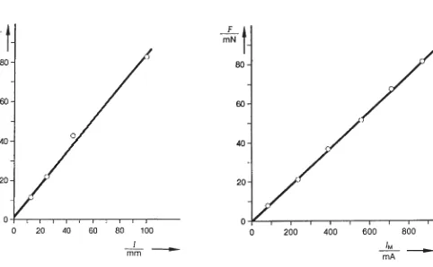
In Fig. 3 the Lorentz force Ffor a fixed current IL= 5 A is plot-ted against the conductor lenght l. We obtain:
F앑IL.
As a result of the influence of the stray field described above, the linear graph in Fig. 3 does not pass exactly through the ori-gin.
3. The experimental results are shown in Fig. 4. The Lorentz forceFis proportional to the current IMin the coils of the
elec-tromagnet :
F앑IM.
Fig. 3: Lorentz force Fas a function of the conductor lenght l
for ⌱L= 5 A. Coil current 870 mA.
Fig. 4: Lorentz force Fas a function of current ⌱Min the coils
Note
If a magnetic-field measuring instrument is available, the magnetic induction can be measured as a function of the coil current. The measurements show that the magnetic induction
Band the coil current IMare proportional in the range under
consideration.
Together with the results from Fig. 4, we therefore obtain
F앑B.


