Japan Patent Office
Title
:
Methane Fermentation
Method and Methane
Fermentation Device
Number
:
4991832
Patentee
:
1.
Metawater Co., Ltd
-‐ Yoshimasa Tomiuchi
2.
University of Sumatera Utara
-‐ Dr. Eng. Ir. Irvan, M.Si
-‐ Ir. Bambang Trisakti, M.Si
-‐ Prof. Dr. Urip Harahap, Apt
-‐ Prof. Darwin Dalimunthe
-‐ Prof. Dr. Erman Munir, MSc
-‐ Dr. Mahyuddin K.M Nasution,
MIT., Ph.D
TITLE OF THE INVENTION
METHANE FERMENTATION METHOD AND METHANE FERMENTATION
APPARATUS
BACKGROUND OF THE INVENTION
1. Field of the Invention
[0001] The present invention relates to a methane fermentation method and a methane
fermentation apparatus capable of subjecting an organic waste to a methane fermentation
treatment stably over a long period of time.
2. Description of the Related Art
[0002] In the methane fermentation treatment, an organic waste is fermented with
methanogens under an anaerobic atmosphere and converts the organic waste into methane gas.
With this treatment, the organic waste is decomposed into biogas and water, and hence, the
organic waste can be reduced remarkably. Further, the methane fermentation treatment has
an advantage of recovering methane gas to be generated as a by-product as energy.
[0003] If a great amount of methanogen can be stored in a methane fermentation tank, the
treatment can be performed at higher speed. As means for storing a great amount of
methanogen in the methane fermentation tank, there is employed a method involving setting a
filter bed for immobilization of bacteria such as methanogen in the methane fermentation tank.
However, such a method has problems such that it makes the maintenance cumbersome and
costly, because of not only the complicated configuration of the apparatus but also the need
for preventing from clogging of the filter bed and the like.
[0004] Further, as a method which does not involve using a filter bed, there is exemplified a
method involving performing methane fermentation by subjecting a fermentation liquid taken
sludge obtained by the solid-liquid separation to the methane fermentation tank or the like.
[0005] For example, Japanese Patent Application Laid-open No. 2006-255571 discloses a
methane fermentation method involving: subjecting an organic waste to a methane
fermentation in a methane fermentation tank; subjecting sludge from the methane
fermentation tank to a solid-liquid separation by a solid-liquid separation unit; returning a part
of the separated sludge obtained by the solid-liquid separation in the solid-liquid separation
unit and a part of a separated liquid obtained by the solid-liquid separation in the solid-liquid
separation unit so that the part of the separated sludge and the part of the separated liquid are
mixed with the organic waste; returning another part of the separated liquid obtained by the
solid-liquid separation in the solid-liquid separation unit so that the another part of the
separated liquid is mixed with the sludge from the methane fermentation tank; and
discharging the remaining of the separated sludge obtained by the solid-liquid separation in
the solid-liquid separation unit and the remaining of the separated liquid obtained by the
solid-liquid separation in the solid-liquid separation unit out of the system. As the
solid-liquid separation unit, there are disclosed mechanical types as solid-liquid separation
units such as a screw press dehydrater, a centrifugal dehydrater, a filter press dehydrater, a
belt press dehydrater, and a multiple disk dehydrater, as well as a solid-liquid separation unit
of sedimentation type.
[0006] Of the solid-liquid separation units disclosed in Japanese Patent Application
Laid-open No. 2006-255571, the solid-liquid separation unit of sedimentation type is
excellent in the running cost because it does not require to charge operational power and the
like.
[0007] However, most of the sedimentation type solid-liquid separation units have no
internal structure for suppressing the turbulence caused by an inflow, the mixing caused by
number increases to impair the sludge sedimentation properties.
[0008] Further, conventionally, the amount of the sludge from the solid-liquid separation
unit returned to the methane fermentation tank and the amount of the liquid waste from the
solid-liquid separation unit discharged out of the system are set constant without being
particularly controlled. However, when the load (due to charging amount and concentration)
of the organic waste in the methane fermentation tank increases, while the viscosity of the
fermentation liquid in the methane fermentation tank increases, thus also increase the sludge
concentration and the viscosity of the fermentation liquid taken out of the methane
fermentation tank. The sedimentation speed of sludge in the sedimentation type solid-liquid
separation unit tends to decrease as the sludge concentration and the viscosity of the
fermentation liquid increase. Therefore, the sedimentation time may not be ensured
sufficiently due to the fluctuation in the load of the organic waste in the methane fermentation
tank, and it may be difficult to return the sludge that is enough concentrated to some required
concentration to the methane fermentation tank. Further, the properties of the liquid
discharged from the sedimentation type solid-liquid separation unit become worse, which
makes the discharge treatment cumbersome. Therefore, in the case where methane
fermentation is performed with the return amount of sludge from the sedimentation
solid-liquid separation unit to the methane fermentation tank and the discharge amount of a
liquid from the solid-liquid separation unit out of the system being constant, it is necessary to
take into account a safety factor considering the fluctuation in the load of the organic waste in
the methane fermentation tank and increase the tank capacity of the sedimentation type
solid-liquid separation unit, which complicates and enlarges the apparatus configuration.
[0009] Patent Publication 1: Japanese Patent Application Laid-open No. 2006-255571.
[0010] An object of the present invention is to provide a methane fermentation method and a
methane fermentation apparatus, capable of keeping a high decomposition ratio with good
time efficiency even without a complicated apparatus configuration.
[0011] In order to solve the above-mentioned problem, the present invention provides a
methane fermentation method including: subjecting an organic waste to a methane
fermentation treatment in a methane fermentation tank; taking a fermentation liquid out of the
methane fermentation tank by predetermined amounts to form a sludge sedimentation liquid
in which the sludge concentration increases toward a lower portion with a gravity
sedimentation unit; returning a liquid having a high sludge concentration on a lower layer side
of the sludge sedimentation liquid to the methane fermentation tank directly or indirectly
through a return line; discharging a liquid having a low sludge concentration on an upper
layer side of the sludge sedimentation liquid out of a system through a discharge line; and
controlling a sum of an amount of the liquid returned through the return line and an amount of
the liquid discharged through the discharge line is substantially equal to an amount of the
fermentation liquid taken out of the methane fermentation tank, characterized in that the
method includes: measuring a sludge concentration of the fermentation liquid in the methane
fermentation tank with a first sludge concentration measuring unit; measuring a sludge
concentration in a predetermined portion of the sludge sedimentation liquid formed with the
gravity sedimentation unit with a second sludge concentration measuring unit; comparing the
sludge concentration measured with the first sludge concentration measuring unit with the
sludge concentration measured with the second sludge concentration measuring unit; and
controlling the amount of the liquid discharged through the discharge line and the amount of
the liquid returned to the methane fermentation tank through the return line so that the sludge
concentration of the liquid discharged through the discharge line is lower than the sludge
sludge concentration of the liquid returned to the methane fermentation tank through the
return line is higher than the sludge concentration of the fermentation liquid in the methane
fermentation tank.
[0012] Further, the present invention provides a methane fermentation apparatus including:
a methane fermentation tank for subjecting an organic waste to a methane fermentation
treatment; a gravity sedimentation unit for subjecting a sludge in a fermentation liquid taken
out of the methane fermentation tank to a gravity sedimentation to form a sludge
sedimentation liquid in which the sludge concentration increases toward a lower potion; a
return line for returning a liquid having a high sludge concentration on a lower layer side of
the sludge sedimentation liquid to the methane fermentation tank directly or indirectly; and a
discharge line for discharging a liquid having a low sludge concentration on an upper layer
side of the sludge sedimentation liquid out of a system, in which a sum of an amount of the
liquid returned through the return line and an amount of the liquid discharged through the
discharge line is controlled to be substantially equal to an amount of the fermentation liquid
taken out of the methane fermentation tank, characterized in that the apparatus includes: a
first sludge concentration measuring unit for measuring a sludge concentration in the
fermentation liquid in the methane fermentation tank; a second sludge concentration
measuring unit for measuring a sludge concentration in a predetermined portion of the sludge
sedimentation liquid formed with the gravity sedimentation unit; and a control device for
comparing the sludge concentration measured with the first sludge concentration measuring
unit with the sludge concentration measured with the second sludge concentration measuring
unit, and controlling an amount of the liquid discharged through the discharge line and an
amount of the liquid returned to the methane fermentation tank through the return line so that
the sludge concentration of the liquid returned to the methane fermentation tank through the
fermentation tank, and the sludge concentration of the liquid discharged through the discharge
line is lower than the sludge concentration of the fermentation liquid in the methane
fermentation tank.
[0013] According to the present invention, depending on the sludge concentration measured
with the first sludge concentration measuring unit and the sludge concentration measured with
the second sludge concentration measuring unit, the amount of the liquid discharged through
the discharge line and the amount of the liquid returned to the methane fermentation tank
through the return line are each controlled so that the sludge concentration of the liquid
discharged through the discharge line is lower than the sludge concentration of the
fermentation liquid in the methane fermentation tank, or so that the sludge concentration of
the liquid returned to the methane fermentation tank through the return line is higher than the
sludge concentration of the fermentation liquid in the methane fermentation tank.
In the case of adjusting the sludge concentration of the liquid discharged through the
discharge line to be lower than the sludge concentration of the fermentation liquid in the
methane fermentation tank, the sludge concentration of the liquid returned to the methane
fermentation tank through the return line after withdrawing the sludge from a lower portion of
the gravity sedimentation unit becomes relatively high. With similarity, in the case of
adjusting the sludge concentration of the liquid returned to the methane fermentation tank
through the return line to be higher than the sludge concentration of the fermentation liquid in
the methane fermentation tank, the sludge concentration of the liquid discharged through the
discharge line from an upper portion of the gravity sedimentation unit becomes relatively low.
Therefore, even when the properties of the organic waste supplied to the methane
fermentation tank change, and the sludge concentration of the fermentation liquid taken out of
the methane fermentation tank is fluctuated, a liquid having a low sludge concentration with
having a high sludge concentration concentrated to a required concentration can be returned
to the methane fermentation tank through the return line. Consequently, an organic
substance to be treated can be subjected to methane fermentation holding a high
decomposition ratio with good time efficiency, while methanogen is retained in the
fermentation tank for a long period of time, without enlarging the gravity sedimentation unit.
[0014] In one embodiment of the present invention, it is preferred that the second sludge
concentration measuring unit be disposed in at least one of a portion above the discharge line
in the gravity sedimentation unit and a portion in the discharge line, the amount of the liquid
discharged through the discharge line be reduced in a case where the sludge concentration
measured with the second sludge concentration measuring unit is higher than the sludge
concentration measured with the first sludge concentration measuring unit, the amount of the
liquid discharged through the discharge line be increased in a case where the sludge
concentration measured with the second sludge concentration measuring unit is lower than the
sludge concentration measured with the first sludge concentration measuring unit, and the
amount of the liquid returned to the methane fermentation tank through the return line be
controlled to be an amount obtainable by subtracting the amount of the liquid discharged
through the discharge line from the amount of the fermentation liquid taken out of the
methane fermentation tank and charged to the gravity sedimentation unit.
According to the above-mentioned embodiment, the sludge concentration of the
liquid discharged through the discharge line can be kept more stable and low, and the sludge
concentration of the liquid returned to the methane fermentation tank through the return line
can be kept relatively high.
[0015] In another embodiment of the present invention, it is preferred that the second sludge
concentration measuring unit be disposed in at least one of a portion below the discharge line
returned to the methane fermentation tank through the return line be increased in a case where
the sludge concentration measured with the second sludge concentration measuring unit is
higher than the sludge concentration measured with the first sludge concentration measuring
unit, the amount of the liquid returned to the methane fermentation tank through the return
line be reduced in a case where the sludge concentration measured with the second sludge
concentration measuring unit is lower than the sludge concentration measured with the first
sludge concentration measuring unit, and the amount of the liquid discharged through the
discharge line be controlled to be an amount obtainable by subtracting the amount of the
liquid returned to the methane fermentation tank through the return line from the amount of
the fermentation liquid taken out of the methane fermentation tank and charged to the gravity
sedimentation unit.
According to the above-mentioned embodiment, the sludge concentration of the
liquid returned to the methane fermentation tank through the return line can be kept more
stable and high, and the sludge concentration of the liquid discharged through the discharge
line can be kept relatively low.
[0016] In the present invention, it is preferred that a slurry adjustment tank for subjecting the
organic waste to a pretreatment to form a slurry be disposed in a former stage of the methane
fermentation tank, and the return line be connected to at least one of the slurry adjustment
tank and the methane fermentation tank.
According to the above-mentioned embodiment, the liquid having a high sludge
concentration formed with the gravity sedimentation unit can be returned to the methane
fermentation tank via the slurry adjustment tank or returned to the methane fermentation tank
directly. In the case of returning the liquid having a high sludge concentration to the
methane fermentation tank via the slurry adjustment tank, the liquid is subjected to a
modified for the liquid to be more easily subjected to the methane fermentation treatment.
Therefore, the treatment efficiency in the methane fermentation tank is enhanced, and higher
decomposition efficiency is attained.
[0017] In addition, in the present invention, it is preferred that the sludge concentration
measuring unit be at least one selected from the group consisting of a viscometer, a
near-infrared scattering light type densitometer, an ultrasonic sludge interface meter, and a
micro-wave densitometer.
[0018] According to the present invention, even when the properties of the organic waste
supplied to the methane fermentation tank change, and the sludge concentration of the
fermentation liquid taken out of the methane fermentation tank is fluctuated, the liquid having
a low sludge concentration with the sludge concentration reduced can be treated and
discharged from the discharge line within a short period of time. Further, the liquid having a
high sludge concentration concentrated to a required concentration can be returned to the
methane fermentation tank from the return line. Therefore, methanogen in the fermentation
tank can be ensured, and the methanogen can take a sufficient residence time. As a result, an
organic waste can be subjected to methane fermentation with a high decomposition ratio
within a short period of time, without using a large gravity sedimentation unit.
BRIEF DESCRIPTION OF THE DRAWINGS
[0019] In the accompanying drawings:
FIG. 1 is a schematic structural view illustrating a first embodiment of the methane
fermentation apparatus of the present invention;
FIG. 2 is a flowchart diagram illustrating a control performed in the control device of
the methane fermentation apparatus according to the first embodiment illustrated in FIG. 1;
methane fermentation apparatus of the present invention; and
FIG. 4 is a flowchart diagram illustrating a control performed in the control device of
the methane fermentation apparatus according to the second embodiment illustrated in FIG. 3.
DETAILED DESCRIPTION OF THE PREFERRED EMBODIMENTS
[0020] A first embodiment of the methane fermentation apparatus of the present invention is
described with reference to FIG. 1.
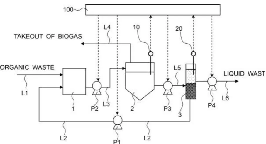
As illustrated in FIG. 1, the methane fermentation apparatus mainly includes a
pretreatment tank 1, a methane fermentation tank 2, and a gravity sedimentation tank 3.
[0021] The pretreatment tank 1 is a treatment tank, that is, a slurry adjustment tank for
subjecting an organic waste sent from a supply source of an organic waste to grinding,
crushing, solubilization, etc. to adjust the organic waste into a slurry. The pretreatment tank
1 also has a buffer function for stabilizing an inflow amount of the organic waste, which is
adjusted into slurry, to the methane fermentation tank 2 described below. To the
pretreatment tank 1, a pipe L1 extending from the supply source of the organic waste and a
pipe L2 (corresponding to the "return line" in the present invention) extending from a bottom
portion of the gravity sedimentation tank 3 (the pipe L2 may be connected to a lower portion
of a side of the sedimentation tank 3) via a pump P1 are connected.
[0022] In the latter stage of the pretreatment tank 1, the methane fermentation tank 2 is
disposed. The pretreatment tank 1 and the methane fermentation tank 2 are connected to
each other via a pipe L3 with a pump P2 interposed.
[0023] The methane fermentation tank 2 is a treatment tank in which the organic waste
(slurry) supplied to the tank is subjected to an anaerobic treatment by the function of
anaerobic bacteria such as methanogen to decompose the organic waste into biogas such as
fermentation liquid in the tank and a first sludge densitometer 10 for measuring the sludge
concentration of the fermentation liquid in the tank are disposed. Further, a pipe L4 for
taking out biogas extends from an upper portion of the methane fermentation tank 2 and is
connected to a gas holder, a gas utilization facility, or the like.
[0024] There is no particular limit to the stirring apparatus as long as the apparatus is
capable of stirring the fermentation liquid in the tank. Examples of the stirring apparatus
include a stirrer equipped with a stirring blade. Further, a mechanism in which a passage for
circulating the fermentation liquid in the tank is formed to generate an upward flow or a
downward flow of the fermentation liquid in the tank may be provided, and a gas stirring
apparatus for circulating the generated biogas to perform blow-bubbling may be provided.
[0025] The first sludge densitometer 10 is not particularly limited, and preferred examples
thereof include a viscometer, a near-infrared scattering light type densitometer, an ultrasonic
sludge interface meter, and a micro-wave densitometer. An example of the viscometer is
"FMV80A" (trade name) marketed by Seconic Corporation. Further, an example of the
near-infrared scattering light type densitometer is "SG-200" marketed by Horiba Advanced
Techno. Further, an example of the ultrasonic sludge interface meter is "SL-200" (trade
name) marketed by Horiba Advanced Techno. Further, as the micro-wave densitometer, "LQ
series" (trade name) commercially available from Toshiba Corporation can be used.
[0026] In the latter stage of the methane fermentation tank 2, the gravity sedimentation tank
3 is disposed. The methane fermentation tank 2 and the gravity sedimentation tank 3 are
connected to each other via a pipe L5 with a pump P3 interposed.
[0027] The gravity sedimentation tank 3 is a treatment tank in which the sludge in the
fermentation liquid taken out from the methane fermentation tank 2 is subjected to a gravity
sedimentation to form a sludge sedimentation liquid with its sludge concentration increasing
Further, by disposing a water flow gradient plate in the gravity sedimentation tank 3, the
sedimentation rate of the sludge can be enhanced further. Examples of the gravity
sedimentation tank equipped with the water flow gradient plate include the tank described in
Japanese Patent Application Laid-open No. H06-63321.
[0028] To a side of the gravity sedimentation tank 3, a pipe L6 (corresponding to the
"discharge line" in the present invention) for discharging a liquid on an upper layer side
having a low concentration of sludge (hereinafter, referred to as "sludge separated liquid") out
of the system is connected. The pipe L6 is connected via a pump P4. Further, the pipe L2
connected to the pretreatment tank 1 extends from a lower portion (bottom portion in this
example) of the gravity sedimentation tank 3 so that at least a part of sludge of a liquid on a
lower layer side having a high concentration of sludge (hereinafter, referred to as "sludge
concentrated liquid") can be returned to the pretreatment tank 1. Further, in the gravity
sedimentation tank 3 in a portion above the portion where the pipe L6 is connected to the
gravity sedimentation tank 3, a second sludge densitometer 20 is disposed. The second
sludge densitometer 20 in this embodiment is disposed so that the concentration of the sludge
separated liquid in the upper layer portion of the sludge sedimentation liquid can be measured
even when the upper surface position of the sludge sedimentation liquid in the gravity
sedimentation tank 3 is fluctuated. As the second sludge densitometer 20, the same
densitometer as the first sludge densitometer 10 described above may be used. Further, it is
preferred that the second sludge densitometer 20 be disposed in the vicinity of a connecting
portion between the gravity sedimentation tank 3 and the pipe L6.
[0029] A control device 100 controls the operations of the pumps P1 and P4 in accordance
with a flowchart illustrated in FIG. 2 described below.
[0030] Next, an operation of a first embodiment of the methane fermentation method of the
fermentation apparatus as an example.
[0031] An organic waste is supplied to the pretreatment tank 1 through the pipes L1 and L2,
and subjected to treatments such as grinding, crushing, and solubilization to be adjusted into a
slurry. The pretreatment method of the organic waste can be changed appropriately
depending upon kinds and properties of the organic waste used for the treatment. For
example, in the case where the organic waste is refuse, raw garbage, animal excreta, or
sewage sludge, it is preferred that the organic waste be mixed with clean water and subjected
to treatments such as grinding and crushing. Further, in the case where the organic waste
contains a great amount of fat contents such as a fat and oil liquid waste, stearic acid, or
palmitic acid, it is preferred that the organic waste be heated to 65°C to 80°C to solubilize.
[0032] The organic waste adjusted into a slurry by the pretreatment is supplied to the
methane fermentation tank 2 by the pump P2 via the pipe L3.
[0033] In the methane fermentation tank 2, the fermentation liquid in the tank is stirred with
a stirring unit (not shown) continuously or intermittently so that the sludge concentration and
the temperature of the fermentation liquid in the tank become substantially uniform. The
sludge concentration of the fermentation liquid in the tank is measured with the first sludge
densitometer 10, and the result of the measurement is input to the control device 100.
[0034] The organic waste (slurry) supplied to the methane fermentation tank 2 is retained in
the methane fermentation tank 2 for a certain period of time, and thus, is subjected to methane
fermentation by the function of anaerobic bacteria such as methanogen. In addition, the
fermentation liquid in the methane fermentation tank 2 in the same amount as that of the
organic waste (slurry) supplied to the methane fermentation tank 2 is withdrawn by the pump
P3 through the pipe L5 and supplied to the gravity sedimentation tank 3. Further, the biogas
such as methane gas generated when the organic waste is subjected to the methane
like (not shown).
[0035] In the gravity sedimentation tank 3, the sludge in the fermentation liquid taken out of
the methane fermentation tank 2 is subjected to a gravity sedimentation to form a sludge
sedimentation liquid with its sludge concentration increasing toward a lower portion, then at
least a part of the sludge sedimentation liquid is discharged by the pump P4 through the pipe
L6, while the remaining part is returned to the pretreatment tank 1 by the pump P1 through
the pipe L2. Further, with the second sludge densitometer 20, the sludge concentration in a
predetermined portion of the sludge sedimentation liquid is measured. In the methane
fermentation apparatus of this embodiment, the second sludge densitometer 20 is disposed in
the gravity sedimentation tank 3 in a portion above the connecting position between the pipe
L6 and the gravity sedimentation tank 3. Therefore, in the second sludge densitometer 20,
the sludge concentration of the sludge separated liquid is measured. Then, the result of the
measurement in the second sludge densitometer 20 is input to the control device 100.
[0036] When the results of the measurement in the first sludge densitometer 10 and the
second sludge densitometer 20 are each input to the control device 100, the control device 100
sends output signals to the pumps P1 and P4 so that the measured value of the second sludge
densitometer 20 is smaller than that of the first sludge densitometer 10, and thus, controls the
liquid amount returned to the pretreatment tank 1 through the pipe L2 (hereinafter, referred
to as "return amount of a sludge concentrated liquid") and the liquid amount discharged
through the pipe L6 (hereinafter, referred to as "discharge amount of a sludge separated
liquid").
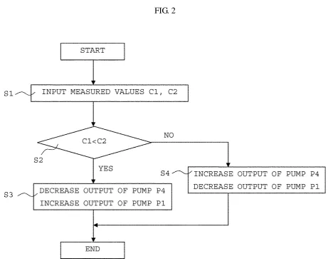
[0037] More specifically, as illustrated in FIG. 2, when the results of the measurement in the
first sludge densitometer 10 and the second sludge densitometer 20 are each input (Step S1), a
measured value C1 of the first sludge densitometer 10 is compared with a measured value C2
[0038] In the case where the measured value C2 of the second sludge densitometer 20 is
larger than the measured value C1 of the first sludge densitometer 10, it means that the sludge
concentration of the sludge separated liquid discharged through the pipe L6 is high.
Therefore, the output of the pump P4 is reduced to decrease the discharge amount of the
sludge separated liquid discharged through the pipe L6. Simultaneously, the output of the
pump P1 is controlled so that the return amount of the sludge concentrated liquid returned
through the pipe L2 is an amount obtainable by subtracting the discharge amount of the
sludge separated liquid from the amount of the fermentation liquid taken out of the methane
fermentation tank 2 and charged to the gravity sedimentation tank 3. Specifically,
decreasing the discharge amount of the sludge separated liquid by reducing the output of the
pump P4 necessitates the increase in the return amount of the sludge concentrated liquid.
densitometer 20 is smaller than the measured value C1 of the first sludge densitometer 10, it
means that the sludge concentration of the sludge separated liquid discharged through the pipe
L6 is low. Therefore, the output of the pump P4 is increased to increase the discharge
amount of the sludge separated liquid discharged through the pipe L6. Simultaneously, the
output of the pump P1 is controlled so that the return amount of the sludge concentrated liquid
returned through the pipe L2 is an amount obtainable by subtracting the discharge amount of
the sludge separated liquid from the amount of the fermentation liquid taken out of the
methane fermentation tank 2 and charged to the gravity sedimentation tank 3. Specifically,
pump P4 necessitates the reduction in the return amount of the sludge concentrated liquid.
Therefore, the output of the pump P1 is reduced (Step S4). Thus, the discharge speed of the
fermentation liquid charged to the gravity sedimentation tank 3 can be maximized, to thereby
enhance the efficiency in a treatment.
[0040] Thus, with such an operation, the sludge separated liquid in such a case of having a
high sludge concentration can prevent from being discharged through the pipe L6.
Therefore, the sludge concentration of the sludge concentrated liquid returned through the
pipe L2 is kept relatively higher, and the bacteria in the sludge can return to the methane
fermentation tank 2 to maintain the amount of the bacteria required for methane fermentation
at all times.
[0041] According to the conventional method, the amount returned from the gravity
sedimentation tank 3 to the methane fermentation tank 2 and the amount discharged out of the
system through the pipe L6 are kept constant. As described above, the sedimentation speed
of sludge in the gravity sedimentation unit tends to decrease as the sludge concentration
increases. Therefore, in order to return the sludge concentrated liquid with its sludge
concentration increased sufficiently to the methane fermentation tank, and to discharge the
sludge separated liquid with its sludge concentration reduced sufficiently out of the system, it
is necessary to take into account a safety factor considering the fluctuation in the load of the
organic waste and increase the tank capacity, which makes the apparatus configuration
complicated.
[0042] In contrast, according to the present invention, the drive of the pumps P1 and P4 is
controlled so that the measured value of the second sludge densitometer 20 is smaller than
that of the first sludge densitometer 10 as described above. Therefore, even when the load of
the organic waste in the methane fermentation tank 2 is fluctuated under the condition that the
sludge separated liquid discharged through the pipe L6 can be kept low, and the sludge
concentration of the sludge concentrated liquid returned to the methane fermentation tank 2
can be kept high. Thus, the organic waste can be subjected to the methane fermentation
efficiently at a high decomposition ratio.
[0043] In this embodiment, the sludge concentrated liquid is returned from the gravity
sedimentation tank 3 to the pretreatment tank 1, thereby returning the sludge concentrated
liquid to the methane fermentation tank 2 indirectly. However, the sludge concentrated
liquid may be returned to the methane fermentation tank 2 directly by connecting the pipe L2
to the methane fermentation tank 2. Even so, it is preferred that the sludge concentrated
liquid be returned to the pretreatment tank 1 because the sludge concentrated liquid, which is
subjected to treatments such as solubilization or the like, and thus, has a feature of more easily
being subjected to the methane fermentation treatment, and as a result, the treatment
efficiency in the methane fermentation tank 2 is enhanced and higher decomposition
efficiency is attained.
[0044] Further, the second sludge densitometer 20 is disposed in a portion above the pipe L6
in the gravity sedimentation tank 3. Alternatively, the second sludge densitometer 20 may
be disposed in the pipe L6 to measure the sludge concentration of the liquid (sludge separated
liquid) passing through the pipe L6 directly.
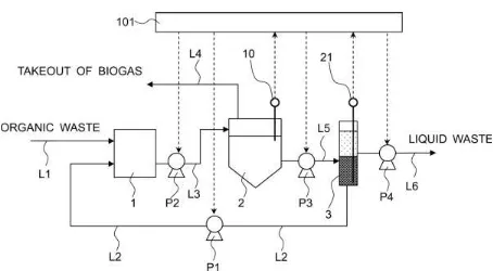
[0045] Next, the second embodiment of the methane fermentation apparatus of the present
invention is described with reference to FIG. 3. It should be noted that portions that are
substantially the same as those of the first embodiment are denoted with the same reference
numerals and the descriptions thereof are omitted.
[0046] The second embodiment is different from the first embodiment in that a second
sludge densitometer 21 is disposed in the gravity sedimentation tank 3 in a portion below the
[0047] More specifically, in this embodiment, the sludge concentration of a liquid having a
high sludge concentration (sludge concentrated liquid) on a lower layer side of the sludge
sedimentation liquid is measured with the second sludge densitometer 21. The second
sludge densitometer 21 is disposed preferably in a bottom portion of the gravity sedimentation
tank 3, and more preferably in the vicinity of the connecting portion between the gravity
sedimentation tank 3 and the pipe L2.
[0048] In this embodiment, when the results of the measurement in the first sludge
densitometer 10 and the second sludge densitometer 21 are each input to the control device
101, the control device 101 sends output signals to the pumps P1 and P4 so that the measured
value of the second sludge densitometer 20 is larger than that of the first sludge densitometer
10, and thus, controls the return amount of the sludge concentrated liquid and the discharge
amount of the sludge separated liquid.
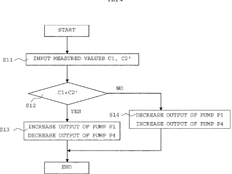
[0049] More specifically, as illustrated in FIG. 4, when the results of the measurement in the
first sludge densitometer 10 and the second sludge densitometer 21 are each input (Step S11),
a measured value C1 of the first sludge densitometer 10 is compared with a measured value
C2' of the second sludge densitometer 21 (Step S12).
[0050] In the case where the measured value C2' of the second sludge densitometer 21 is
larger than the measured value C1 of the first sludge densitometer 10, it means that the sludge
concentration of the sludge concentrated liquid returned through the pipe L2 is high.
Therefore, the output of the pump P1 is increased to increase the amount of the sludge
concentrated liquid returned through the pipe L2. Simultaneously, the output of the pump P4
is controlled so that the discharge amount of the sludge separated liquid discharged through
the pipe L6 is an amount obtainable by subtracting the amount of the sludge concentrated
liquid returned through the pipe L2 from the amount of the fermentation liquid taken out of
Specifically, increasing the return amount of the sludge concentrated liquid by increasing the
densitometer 21 is smaller than the measured value C1 of the first sludge densitometer 10, it
means that the sludge concentration of the sludge concentrated liquid returned through the
pipe L2 is low. Therefore, the output of the pump P1 is reduced to decrease the amount of
the sludge concentrated liquid returned through the pipe L2. Simultaneously, the output of
the pump P4 is controlled so that the discharge amount of the sludge separated liquid
discharged through the pipe L6 is an amount obtainable by subtracting the amount of the
sludge concentrated liquid returned through the pipe L2 from the amount of the fermentation
liquid taken out of the methane fermentation tank 2 and charged to the gravity sedimentation
tank 3. Specifically, reducing the return amount of the sludge concentrated liquid by
reducing the output of the pump P1 necessitates the increase in the discharge amount of the
sludge separated liquid. Therefore, the output of the pump P4 is increased (Step S14).
Thus, the liquid in such a case of having a low sludge concentration can be prevented from
returning to the methane fermentation tank 2, as a result the concentration of bacteria in the
methane fermentation tank 2 can be prevented from decreasing.
[0052] Thus, with such an operation, the sludge is returned to the methane fermentation tank
2 efficiently. Therefore, the sludge concentration of the sludge separated liquid discharged
through the pipe L6 is kept relatively low, which can make easy the subsequent discharge
treatment.
controlled while the sludge concentration of the sludge concentrated liquid is measured.
Therefore, the sludge concentrated liquid concentrated more surely to a desired sludge
concentration, preferably by 1.5 to 3 times, more preferably by 2 to 3 times of the sludge
concentration of the fermentation liquid in the methane fermentation tank 2, can be returned
to the methane fermentation tank 2 directly or indirectly.
[0054] The second sludge densitometer 21 is disposed in a bottom portion of the gravity
sedimentation tank 3 in this embodiment. Alternatively, the second sludge densitometer 21
may be disposed in the pipe L1 to measure the sludge concentration of the liquid (sludge
concentrated liquid) passing through the pipe L1 directly.
[0055] Further, the operation for taking out the fermentation liquid from the methane
fermentation tank 2 and charging it to the gravity sedimentation tank 3 may be performed
continuously or intermittently at predetermined time intervals. In the case where the
fermentation liquid is charged to the gravity sedimentation tank 3 intermittently, if the sum of
the return amount of the sludge concentrated liquid and the discharge amount of the sludge
separated liquid reaches the amount of the fermentation liquid charged from the methane
fermentation tank 2 to the gravity sedimentation tank 3, the drive of the pumps P1 and P4 may
be stopped and the fermentation liquid may be charged from the methane fermentation tank 2
to the gravity sedimentation tank 3 again.
[0056] Further, a level meter for measuring a liquid surface level in a tank may be disposed
in the methane fermentation tank 2 and the gravity sedimentation tank 3, and the drive of the
pumps P2 and P3 may be controlled so that the liquid surface level in each tank is within a
predetermined range. For example, if the liquid surface level in the methane fermentation
tank 2 exceeds a predetermined value, the drive of the pump P3 is increased while stopping or
reducing the drive of the pump P2. Further, if the liquid surface level in the methane
while stopping or reducing the drive of the pump P3. Further, if the liquid surface level in
the gravity sedimentation tank 3 exceeds the predetermined value, the drive of the pump P3 is
stopped or reduced. Further, if the liquid surface level in the gravity sedimentation tank 3 is
below the predetermined value, the drive of the pump P3 is increased.
Examples
[0057] (Example 1)
Methane fermentation was performed using the methane fermentation apparatus
illustrated in FIG. 1. As the methane fermentation tank 2, a tank with a capacity of 5 L was
used. As the gravity sedimentation tank 3, a tank with a capacity of 0.5 L was used.
Further, as the sludge densitometers 10 and 20, an oscillation type viscometer "VM-10A"
(trade name, produced by SECONIC Corporation) was used. Further, as the organic waste, a
mixed sludge (in which the ratio of the TS concentration of initial sedimentation sludge to the
TS concentration of excessive sludge is 6:4) from a sewage plant, having a solid
concentration of about 30,000 mg/L and a concentration of a non-volatile organic substance
(VS) of about 25, 000 mg/L was used.
It should be noted that the TS concentration (residue after evaporation) was
measured in accordance with a sewage test method-2.2.9. More specifically, the TS
concentration of the sample liquid was obtained by dividing the amount of the remaining solid
after drying at 110ºC by the original volume of the sample liquid. Further, the VS
concentration of the fermentation liquid was obtained by subtracting the ash concentration,
obtained by dividing the mass of the remaining solid after heating at 600ºC±25ºC by the
original volume of the sample liquid, from the TS concentration of the fermentation liquid
(mg/L) (value obtained by dividing the mass of the remaining solid after drying at 110ºC by
A slurry was charged to the methane fermentation tank 2 from the pretreatment tank
withdrawn from the methane fermentation tank 2, and then the slurry was supplied.
During methane fermentation, the drive of the pumps P1 and P4 was controlled in
accordance with the flowchart illustrated in FIG. 2 so that the measured value with the first
sludge densitometer 10 was larger than that with the second sludge densitometer 20, to
thereby control the liquid amount returned to the pretreatment tank 1 through the pipe L2 and
the liquid amount discharged through the pipe L6. The amount of the liquid returned to the
pretreatment tank 1 through the pipe L2 was set to be an amount obtainable by subtracting the
amount of the liquid discharged through the pipe L6 from the amount of the fermentation
liquid charged to the gravity sedimentation tank 3.
The VS concentration of the fermentation liquid, after the elapse of 30 days from
reaching the condition of the residence time of 10 days, was measured to be 10,500 mg/L, and
the ratio of the VS decomposition was 58.0%.
[0058] (Example 2)
Methane fermentation was performed in the same way as in Example 1, except that
the drive of the pumps P1 and P4 was controlled in accordance with the flowchart illustrated
in FIG. 4 to control the amount of the liquid returned to the pretreatment tank 1 through the
pipe L2 and the amount of the liquid discharged through the pipe L6 so that the measured
value by the first sludge densitometer 10 was smaller than that by the second sludge
illustrated in FIG. 3. The liquid amount discharged through the pipe L6 was set to be an
amount obtained by subtracting the amount of liquid returned to the pretreatment tank 1
through the pipe L2 from the amount of the fermentation liquid charged to the gravity
sedimentation tank 3.
The VS concentration of the fermentation liquid, after the elapse of 30 days from
reaching the condition of the residence time of 10 days, was measured to be 10,100 mg/L, and
the ratio of the VS decomposition was 59.6%.
[0059] (Comparative Example 1)
Methane fermentation was performed in the same way as in Example 1, except that
the total amount of the liquid in the gravity sedimentation tank 3 was discharged through the
pipe L6 in Example 1.
The VS concentration of the fermentation liquid, after the elapse of 30 days from
reaching the condition of the residence time of 10 days in the methane fermentation tank 2 of
the organic waste charged to the methane fermentation tank 2 (500mL to be charged per day),
was measured to be 11,600 mg/L, and the ratio of the VS decomposition was 53.6%.
[0060] (Comparative Example 2)
Methane fermentation was performed in the same way as in Example 1, except that
the amount of the liquid returned to the pretreatment tank 1 through the pipe L2 from the
gravity sedimentation tank 3 was set at 50 mL and the amount of the liquid discharged
through the pipe L6 was set at 500 mL in Example 1.
The VS concentration of the fermentation liquid, after the elapse of 30 days from
reaching the condition of the residence time of 10 days in the methane fermentation tank 2 of
the organic waste charged to the methane fermentation tank 2, was measured to be 11,300
WHAT IS CLAIMED IS:
1. A methane fermentation method, comprising:
subjecting an organic waste to a methane fermentation treatment in a methane
fermentation tank;
taking a fermentation liquid out of the methane fermentation tank by predetermined
amounts to form a sludge sedimentation liquid in which the sludge concentration increases
toward a lower portion with a gravity sedimentation unit;
returning a liquid having a high sludge concentration on a lower layer side of the
sludge sedimentation liquid to the methane fermentation tank directly or indirectly through a
return line;
discharging a liquid having a low sludge concentration on an upper layer side of the
sludge sedimentation liquid out of a system through a discharge line; and
controlling a sum of an amount of the liquid returned through the return line and an
amount of the liquid discharged through the discharge line to be substantially equal to an
amount of the fermentation liquid taken out of the methane fermentation tank,
characterized in that the method comprises:
measuring a sludge concentration of the fermentation liquid in the methane
fermentation tank with a first sludge concentration measuring unit;
measuring a sludge concentration in a predetermined portion of the sludge
sedimentation liquid formed with the gravity sedimentation unit with a second sludge
concentration measuring unit;
comparing the sludge concentration measured with the first sludge concentration
measuring unit with the sludge concentration measured with the second sludge concentration
measuring unit; and
amount of the liquid returned to the methane fermentation tank through the return line so that
the sludge concentration of the liquid discharged through the discharge line is lower than the
sludge concentration of the fermentation liquid in the methane fermentation tank, or so that
the sludge concentration of the liquid returned to the methane fermentation tank through the
return line is higher than the sludge concentration of the fermentation liquid in the methane
fermentation tank.
2. A methane fermentation method according to claim 1, wherein the second sludge
concentration measuring unit is disposed in at least one of a portion above the discharge line
in the gravity sedimentation unit and a portion in the discharge line, the amount of the liquid
discharged through the discharge line is reduced in a case where the sludge concentration
measured with the second sludge concentration measuring unit is higher than the sludge
concentration measured with the first sludge concentration measuring unit, the amount of the
liquid discharged through the discharge line is increased in a case where the sludge
concentration measured with the second sludge concentration measuring unit is lower than the
sludge concentration measured with the first sludge concentration measuring unit, and the
amount of the liquid returned to the methane fermentation tank through the return line is
controlled to be an amount obtainable by subtracting the amount of the liquid discharged
through the discharge line from the amount of the fermentation liquid taken out of the
methane fermentation tank and charged to the gravity sedimentation unit.
3. A methane fermentation method according to claim 1, wherein the second sludge
concentration measuring unit is disposed in at least one of a portion below the discharge line
in the gravity sedimentation unit and a portion in the return line, the amount of the liquid
the sludge concentration measured with the second sludge concentration measuring unit is
higher than the sludge concentration measured with the first sludge concentration measuring
unit, the amount of the liquid returned to the methane fermentation tank through the return
line is reduced in a case where the sludge concentration measured with the second sludge
concentration measuring unit is lower than the sludge concentration measured with the first
sludge concentration measuring unit, and the amount of the liquid discharged through the
discharge line is controlled to be an amount obtainable by subtracting the amount of the liquid
returned to the methane fermentation tank through the return line from the amount of the
fermentation liquid taken out of the methane fermentation tank and charged to the gravity
sedimentation unit.
4. A methane fermentation method according to any one of claims 1 to 3, wherein a
slurry adjustment tank for subjecting the organic waste to a pretreatment to form a slurry is
disposed in a former stage of the methane fermentation tank, and the return line is connected
to at least one of the slurry adjustment tank and the methane fermentation tank.
5. A methane fermentation apparatus, comprising: a methane fermentation tank for
subjecting an organic waste to a methane fermentation treatment; a gravity sedimentation unit
for subjecting a sludge in a fermentation liquid taken out of the methane fermentation tank to
a gravity sedimentation to form a sludge sedimentation liquid in which the sludge
concentration increases toward a lower potion; a return line for returning a liquid having a
high sludge concentration on a lower layer side of the sludge sedimentation liquid to the
methane fermentation tank directly or indirectly; and a discharge line for discharging a liquid
having a low sludge concentration on an upper layer side of the sludge sedimentation liquid
and an amount of the liquid discharged through the discharge line is controlled to be
substantially equal to an amount of the fermentation liquid taken out of the methane
fermentation tank,
characterized in that the apparatus comprises:
a first sludge concentration measuring unit for measuring a sludge concentration in
the fermentation liquid in the methane fermentation tank;
a second sludge concentration measuring unit for measuring a sludge concentration
in a predetermined portion of the sludge sedimentation liquid formed with the gravity
sedimentation unit; and
a control device for comparing the sludge concentration measured with the first
sludge concentration measuring unit with the sludge concentration measured with the second
sludge concentration measuring unit, and controlling an amount of the liquid discharged
through the discharge line and an amount of the liquid returned to the methane fermentation
tank through the return line so that the sludge concentration of the liquid returned to the
methane fermentation tank through the return line is higher than the sludge concentration of
the fermentation liquid in the methane fermentation tank, and the sludge concentration of the
liquid discharged through the discharge line is lower than the sludge concentration of the
fermentation liquid in the methane fermentation tank.
6. A methane fermentation apparatus according to claim 5, wherein the second sludge
concentration measuring unit is disposed in at least one of a portion above the discharge line
in the gravity sedimentation unit and a portion in the discharge line, and wherein the control
device is disposed to control so that the amount of the liquid discharged through the discharge
line is reduced in a case where the sludge concentration measured with the second sludge
sludge concentration measuring unit, the amount of the liquid discharged through the
discharge line is increased in a case where the sludge concentration measured with the second
sludge concentration measuring unit is lower than the sludge concentration measured with the
first sludge concentration measuring unit, and the amount of the liquid returned to the
methane fermentation tank through the return line is controlled to be an amount obtainable by
subtracting the amount of the liquid discharged through the discharge line from the amount of
the fermentation liquid taken out of the methane fermentation tank and charged to the gravity
sedimentation unit.
7. A methane fermentation apparatus according to claim 5, wherein the second sludge
concentration measuring unit is disposed in at least one of a portion below the discharge line
in the gravity sedimentation unit and a portion in the return line, and wherein the control
device is disposed to control so that the amount of the liquid returned to the methane
fermentation tank through the return line is increased in a case where the sludge concentration
measured with the second sludge concentration measuring unit is higher than the sludge
concentration measured with the first sludge concentration measuring unit, the amount of the
liquid returned to the methane fermentation tank through the return line is reduced in a case
where the sludge concentration measured with the second sludge concentration measuring
unit is lower than the sludge concentration measured with the first sludge concentration
measuring unit, and the amount of the liquid discharged through the discharge line is
controlled to be an amount obtainable by subtracting the amount of the liquid returned to the
methane fermentation tank through the return line from the amount of the fermentation liquid
taken out of the methane fermentation tank and charged to the gravity sedimentation unit.
slurry adjustment tank for subjecting the organic waste to a pretreatment to form a slurry is
disposed in a former stage of the methane fermentation tank, and the return line is connected
to at least one of the slurry adjustment tank and the methane fermentation tank.
9. A methane fermentation apparatus according to any one of claims 5 to 8, wherein
the sludge concentration measuring unit is at least one selected from the group consisting of a
viscometer, a near-infrared scattering light type densitometer, an ultrasonic sludge interface
ABSTRACT OF THE DISCLOSURE
Provided is a methane fermentation method and a methane fermentation apparatus,
capable of keeping a high decomposition ratio with good time efficiency even without a
complicated apparatus configuration. Methane fermentation is performed using a methane
fermentation apparatus that includes a first sludge concentration measuring unit (10) for
measuring a sludge concentration in the fermentation liquid in a methane fermentation tank
(2), a second sludge concentration measuring unit (20) for measuring a sludge concentration
in a predetermined portion of a sludge sedimentation liquid formed with a gravity
sedimentation unit (3), and a control device (100) for comparing the sludge concentration
measured with the first sludge concentration measuring unit (10) with the sludge
concentration measured with the second sludge concentration measuring unit (20), and
controlling an amount of the liquid so that the sludge concentration of the liquid returned to
the methane fermentation tank (2) through a return line (L2) is higher than the sludge
concentration of the fermentation liquid in the methane fermentation tank (2), and the sludge
concentration of the liquid discharged through a discharge line (L6) is lower than the sludge