FINAL PROJECT – ME141502
STRENGTH ANALYSIS OF VERTICAL AXIS
TURBINE SHAFT FOR 5 KW CAPACITY
ON OCEAN CURRENT POWER PLANT
DHAIFINA SUCI SORAYA4212 101 007
Supervisor :
Irfan Syarif Arief, S.T., M.T. Ir. Tony Bambang Musrijadi, PGD
MARINE ENGINEERING DEPARTMENT FACULTY OF MARINE TECHNOLOGY
INSTITUT TEKNOLOGI SEPULUH NOPEMBER SURABAYA
TUGAS AKHIR – ME141502
ANALISA KEKUATAN POROS TURBIN
VERTIKAL UNTUK KAPASITAS 5 KW
PADA PEMBANGKIT LISTRIK TENAGA
ARUS LAUT (PLTAL)
DHAIFINA SUCI SORAYA 4212 101 007
Dosen Pembimbing :
Irfan Syarif Arief, S.T., M.T. Ir. Tony Bambang Musrijadi, PGD
JURUSAN TEKNIK SISTEM PERKAPALAN FAKULTAS TEKNOLOGI KELAUTAN
INSTITUT TEKNOLOGI SEPULUH NOPEMBER SURABAYA
ix
ON OCEAN CURRENT POWER PLANT
Name : Dhaifina Suci Soraya
ID Number : 4212101007
Department : Marine Engineering
Supervisor : 1. Irfan Syarif Arief, S.T., M.T. 2. Ir. Tony Bambang M., PGD ABSTRACT
The diversity of Indonesia's natural resources saves a lot of potential that can be developed. One of them is the potential of ocean current energy resources. Ocean current energy is one of renewable energy. In its utilization, it requires a turbine that will change the ocean current energy to become electric energy, named ocean current power plant. In its designing is needed a lot of requirement. Shaft is the main component that is important from a mechanical transmission system on ocean current power plant. The purpose of this research was to find out on appropriate shaft specification, then analyze the safety factor, strength ability of the material, and the deformation may be occurred on the shaft by using Finite Element Analysis Method, that implemented in Solid work simulation, a design tool. Calculation of force and load as well as the design of the shaft diameter is a very important factor in determining strength analysis. The results from this research showed the appropriate shaft is made by solid shaft with high tensile steel AISI 4140 material, where it has good ductility, good wear resistance, and corrosion resistance. Vertical axis turbine shaft arranged a series of three shafts having a length respectively 3,3 m, 2 m, and 2 m. The maximum stress is 144,061946 MPa and it is operated with factor of safety 4,5. Keywords : ocean current, vertical axis turbine, shaft
xi
LISTRIK TENAGA LISTRIK ARUS LAUT (PLTAL) Nama : Dhaifina Suci Soraya
NRP : 42121010007
Jurusan : Marine Engineering
Dosen Pembimbing : 1. Irfan Syarif Arief, S.T., M.T. 2. Ir. Tony Bambang M., PGD ABSTRAK
Sumber daya alam Indonesia menyimpan banyak potensi yang bisa dikembangkan. Salah satunya adalah mengembangkan potensi sumber daya energi arus laut. Energi arus laut merupakan sumber daya terbarukan yang sangat potensial untuk dikonversikan menjadi energi listrik. Dalam pemanfaatannya, menggunakan turbin pada pembangkit listrik tenaga arus laut (PLTAL). Dalam merancang suatu pembangkit listrik tenaga arus laut dibutuhkan banyak perhitungan. Poros merupakan komponen utama yang penting dari sistem transmisi mekanik pada pembangkit listrik. Tujuan dari penelitian ini adalah untuk menentukan spesifikasi poros yang tepat, kemudian menganalisa faktor keamanan, kekuatan material, dan deformasi yang dapat terjadi pada poros dengan menggunakan Finite Element Analysis
Method, yang diimplementasikan dalam simulasi Solidwork.
Perhitungan gaya dan beban yang diterima poros serta perhitungan diameter poros merupakan faktor yang sangat penting dalam menentukan analisa kekuatan. Hasil dari penelitian ini menunjukkan poros yang tepat adalah berbahan pejal dengan material High Tensile AISI 4140, dimana ia memiliki daktilitas yang baik, ketahanan aus yang baik, dan ketahanan korosi. Poros turbin vertikal disusun dari tiga poros yang memiliki panjang masing-masing 3,3 m, 2 m, dan 2 m. Tegangan maksimum didapatkan 144,061946 MPa dengan faktor keamanan 4,5.
xv
DECLARATION OF HONOUR ... vii
ABSTRACT ... ix
ABSTRAK ... xi
PREFACE ... xiii
TABLE OF CONTENTS ... xv
LIST OF FIGURES ... xix
LIST OF TABLES ... xxi
LIST OF ATTACHMENT ... xxiii
CHAPTER 1 INTRODUCTION ... 1
1.1.
Background ... 1
1.2.
Statement of Problems ... 2
1.3.
Scope of Problems ... 3
1.4.
Research Objectives ... 3
1.5.
Research Benefits ... 4
CHAPTER 2 STUDY LITERATURE ... 5
2.1
Concept of Ocean Current Power Plant ... 5
2.1.1 TLP (Tension Light Platform) ... 6
2.2
Turbine ... 7
2.3
Shaft ... 8
2.3.1 Material Used for Shaft ... 8
2.3.2 Manufacturing of Shaft ... 9
2.3.3 Types of Shaft ... 10
2.3.4 Standard Sizes of Transmission Shaft... 10
2.3.5 Types of Stresses in Shaft ... 10
2.3.6 Maximum Permissible Working Stresses for Transmission Shaft ... 11
2.3.8 Calculation of Force on The Shaft ... 13
2.3.9 Calculation Reaction Force and Moment Area Horizontal ... 14
2.3.10 Calculation Reaction Force and Moment Area Vertical ... 15
2.3.11 Calculation Shaft Dimension ... 17
2.4
Bearing...21
2.4.1 Thrust Ball Bearing ... 23
2.5
Shaft Coupling ...24
2.6
Material Properties ...25
2.6.1 Deformation ... 26
2.6.2 Elasticity ... 26
2.7
Material Mechanical Properties ...26
2.7.1 Hardness ... 28 2.7.2 Tensile Strength, su ... 28 2.7.3 Yield Strength, sy ... 29 2.7.4 Modulus of Elasticity ... 29
2.8
Stresses ...30
2.8.1 Normal Stress ... 30 2.8.2 Tensile Stress ... 31 2.8.3 Compressive Stress ... 32 2.8.4 Shear Stress ... 32 2.8.5 Strain ... 332.9
Load ...34
2.10
Safety Factor (
sf) ...34
2.11
Finite Element Analysis Method ...35
CHAPTER 3 RESEARCH METHODS ...39
CHAPTER 4 DATA ANALYSIS...45
4.1
Analysis of Ocean Current Platform Concept ...45
xvii
4.4.1 Shaft Material ... 48
4.4.2 Shaft Design Calculation ... 49
4.4.3 Support Component on Shaft... 60
4.5
Finite Element Simulation ... 62
4.5.1 Modelling ... 62 4.5.2 Simulation Output ... 64 4.5.2.1 Stress ... 64 4.5.2.2 Strain ... 65 4.5.2.3 Displacement ... 66 4.5.2.4 Factor of Safety ... 67
CHAPTER 5 CONCLUSION ... 69
5.1
Conclusion ... 69
5.2
Recommendation ... 70
REFERENCES ... 71
ATTACHMENT ... 73
xix
Figure 2.1 Ocean Current Platform [10] ... 6
Figure 2.2 Tension Light Platform (TLP) ... 6
Figure 2.3 Vertical Axis Turbine [3] ... 7
Figure 2.4 Shaft and Pulley ... 13
Figure 2.5 Forces on The Shaft ... 14
Figure 2.6 Horizontal Reaction Force ... 14
Figure 2.7 Moment Area Horizontal ... 15
Figure 2.8 Vertical Reaction Force ... 16
Figure 2.9 Moment Area Vertical... 16
Figure 2.10 Radial and Thrust Bearing ... 22
Figure 2.11 Sliding and Rolling Contact Bearing ... 23
Figure 2.12 Thrust Ball Bearing ... 23
Figure 2.13 Flexible Coupling ... 25
Figure 2.14 Typical Stress – Strain Diagram for Steel ... 27
Figure 2.15 Typical Stress – Strain Diagram for Aluminium and other metals having no yield point ... 28
Figure 2.16 Material Block ... 31
Figure 2.17 Tensile Stress on Block ... 31
Figure 2.18 Comprassive Stress on Block ... 32
Figure 2.19 Shear Stress on Block... 32
Figure 2.20 Strain on Material Block ... 33
Figure 2.21 Finite Element Concept ... 36
Figure 4.1 Tension Light Platform... 45
Figure 4.2 Darrieus Turbine Model – NACA 0018 ... 46
Figure 4.3 Turbine Shaft ... 47
Figure 4.4 Force on Turbine Shaft... 49
Figure 4.5 Distribution Shear Force ... 49
Figure 4.6 Moment Diagram ... 50
Figure 4.7 Bearing SKF 81110 ... 60
Figure 4.8 Flexible Coupling ... 61
Figure 4.9 Dimension of Flexible Coupling ... 61
Figure 4.10 Vertical Axis Turbine 3D Model ... 63
Figure 4.12 Strain Output ... 65 Figure 4.13 Displacement Output ... 66 Figure 4.14 Safety Factor Output ... 67
xxi
Table 2.1 Mechanical Properties of Steels Used for Shafts [8]... 9
Table 2.2 Recommended values for Km and Kt... 20
Table 4.1 List of Component... 62
Table 4. 2 Summary of Stress Output ... 64
Table 4. 3 Summary of Strain Output ... 65
Table 4.4 Summary of Displacement Output ... 66
xxiii
Attachment 1 Catalogue of Rolling Bearings Attachment 2 Catalogue of Couplings
Attachment 3 Material 1 – AISI 4140 High Tensile Steel Attachment 4 Material 2 – AISI 1045 Medium Tensile Carbon
Steel
Attachment 5 Material 3 – AISI 316 Stainless Steel Attachment 6 Simulation of Hollow Shaft - Material 1 Attachment 7 Simulation of Solid Shaft - Material 1 Attachment 8 Simulation of Hollow Shaft - Material 2 Attachment 9 Simulation of Solid Shaft - Material 2 Attachment 10 Simulation of Hollow Shaft - Material 3 Attachment 11 Simulation of Solid Shaft – Material 3
1
INTRODUCTION
1.1. Background
Electricity is a basic requirement of society and supports in all aspect and for national development, including the improvement of living standards. Various attempts were made to overcome the electricity crisis by doing various research and development of alternative technologies and renewable energy. That is because the availability of electricity gradually always smaller than the growing need. The diversity of Indonesia's natural resources saves a lot of potential that can be developed. One that can be developed is the potential of ocean current energy resources. An ocean current energy resource is potential to be converted into electrical energy. It utilizes marine kinetic energy by using the motion of ocean currents. Based on the results of the current velocity measurement and modeling that have been done in the Selat Toyapakeh of Nusa Penida are noted that in this location has practical potential energy of ocean currents. Therefore, it will be designed ocean current power plant in that area to develop the potential exists. The research and development of power plant technology of ocean currents also accordance with the Strategic Plan of Ministry of Energy and Mineral Resources 2010 – 2014, mentioned that one of the strategic objectives associated with the purpose of ensuring the supply of domestic energy and raw materials is increasing development of various sources of energy in order to diversify the energy, by encouraging the construction of power plants, in order to solve the problem of electric energy in the archipelago, so
it can support Indonesia became an independent archipelago state and developed.
In the designing of ocean current power plants, exactly it needs many calculation and proper planning, one of them is designing the technology of mechanical transmission system. Certainly, it will need mathematical and technical calculations to determine and select the components and materials that are needed. The main component that is important from a mechanical transmission system is the shaft. Shaft is a rotating machine element which is used to transmit power. The power is delivered to the shaft by some tangential force and the resultant torque (or twisting moment) set up within the shaft permits the power to be transferred to various machines linked up to the shaft. In this case needs to design the transmission shaft to transmit power from vertical axis turbine wheel to gearbox and generator and then choose the material and analyze its structural strength include safety factor, stress, strain, deformation may be occurred.
In this final project, the analysis will do according to the data of rotating speed (rpm), torque, and power to be received by shaft, as well as analyzing the strength ability of the material while receiving some kind of stress in the process of loading received, strain, safety factor, deformation that may be occurred on the shaft using Finite Element Analysis Method that implemented in Solidwork simulation, a design tool.
1.2. Statement of Problems
According to the background of the study, this final project has the following statement of problems.
a) How the design calculation of vertical axis turbine shaft for a mechanical transmission system of ocean currents power plant.
b) How the strength analysis and its safety factor of vertical axis turbine shaft material while receiving some kind of stress on the loads process.
1.3. Scope of Problems
According to the research problem, this final project has the following scopes.
a) The design calculation and strength analysis of vertical axis turbine shaft are carried out according to existing source of rotating speed (rpm), torque, and power data of turbine.
b) Determine the dimension of the shaft (shaft specification), then analyze the safety factor, strength ability of the material, the deformation may be occurred on the shaft by using Finite Element Analysis Method, that implemented in Solidwork simulation, a design tool.
c) The analysis will only focused on the shaft of vertical axis turbine, as a transmission shaft and its support component for mechanical transmission system. The next concept of mechanical transmission system such as gearbox system and selecting generator will not taken into consideration.
1.4. Research Objectives
In accordance with the background of the study, this final project has these following objectives.
a) To design and to analyze the strength ability of vertical axis turbine shaft, as transmission shaft on ocean current power plant.
b) To find out an appropriate spesification of transmission shaft that capable for certain capacity on ocean current power plant.
1.5. Research Benefits
This final project will be able to give these following benefits.
a) Knowing the design and strength analysis of vertical axis turbine shaft, as transmission shaft of ocean current power plant.
b) Knowing the appropriate spesification of transmission shaft that capable for certain capacity on ocean current power plant.
c) The result of this final project is expected to be used as reference in designing of vertical axis turbine shaft for mechanical transmission system of ocean currents power plant in Selat Toyopakeh, Nusa Penida, and can work maximally.
5
STUDY LITERATURE
2.1 Concept of Ocean Current Power Plant
In the life society, electricity is the energy has an important role. Almost everyday people always using electricity in the activities they perform. Electricity itself is obtained from conversion of kinetic energy into electrical energy. Energy Kinetic itself can be obtained from combustion sources energy derived from fossil fuels. However, availability of energy derived from fossil reduced. It makes the issue of innovation renewable energy.
Indonesia is the country with the potential for large sea. There are several forms of energy of the sea that can be used, such as ocean thermal, wave, wind, tidal, and ocean currents. Due to the global climate change and the energy crisis, the clean renewable ocean current energy with high energy density and good predictability has attracted an increasing attention [11].
The power plant was developed in a variety of energy exploitation, such as power of ocean currents (tidal current energy). Ocean current energy offers a vast and reliable energy source [7].
Ocean currents platform are offshore building convert ocean currents into electric energy with utilizing the rotation of the ocean current turbine. Ocean current turbine produce more energy than wind turbines, with the same dimensions of turbine and current velocity.
Figure 2.1 Ocean Current Platform [10]
2.1.1 TLP (Tension Light Platform)
There are several types of platforms for ocean current power plant. One of the types is TLP (Tension Light Platform). TLP is a platform with a simple type of box that has some properties :
1. Remotely operated units
2. Installation of topsides in one operation, reducing the offshore hook-ups
3. Suitable to develop a large deposit in deep waters or very deep waters
4. Has a lower movement region
5. Able was at a depth of up to 2000 meters
2.2 Turbine
Exploitation of ocean current energy use turbine device. A turbine is rotary mechanical device that extracts energy from a fluid flow and converts it into useful work. In water turbines, ocean current will rotate the turbine and there is a generator that will convert the rotation of the turbine into electricity [11].
Based on the alignment of the rotor axis with respect to water flow, three generic classes could be formed horizontal axis (HAT), vertical axis (VAT), and cross flow turbines [3]. It is proven that the turbine model of the vertical axis (VAT) is a model turbine that appropriate in energy utilization of ocean current. Vertical axis turbine system has many advantages, especially on the side of simple design and lower cost, when compared with the wheelbase horizontal-type turbines . The types of vertical axis turbine classified into 6, they are SC-Darrieus (straight blade), H-Darrieus (straight blade), Darrieus (curved blade), Gorlov (helical blade), and Savonius (straight/sweked) [4].
2.3 Shaft
A shaft is a rotating machine element which is used to transmit power from one place to another. The power is delivered to the shaft by some tangential force and the resultant torque (or twisting moment) set up within the shaft permits the power to be transferred to various machines linked up to the shaft. [8].
Visualize the forces, torques, and bending moments that are created in the shaft during operation. In the process of transmitting power at a given rotational speed, the shaft is inherently subjected to a torsional moment, or torque. Thus, torsional shear stress is developed in the shaft. Also, a shaft usually cairies power-transmitting components, such as gears, belt sheaves, or chain sprockets, which exert forces on the shaft in the transverse direction (perpendicular to its axis). These transverse forces cause bending moments to be developed in the shaft, requiring analysis ofthe stress due to bending. In fact, most shafts must be analyzed for combined stress. [6]
2.3.1 Material Used for Shaft
In general, the material used for ordinary shafts is carbon steel of grades 40 C 8, 45 C 8, 50 C 4 and 50 C 12. The mechanical properties of these grades of carbon steel are given in the following table. When a shaft of high strength is required, then an alloy steel such as nickel, nickel-chromium or chrome-vanadium steel is used, such as ASME 1347, 3140, 4150, 5145, and so on. If the shaft necessary surface hardening, it is necessary used carburising steel material such as ASME 1020, 1117, 2315, 4320, 8620 or G4102, G4103, G4104. [9]
Table 2.1 Mechanical Properties of Steels Used for Shafts [8] Indian
Standard Designation
Ultimate Tensile
Strength, MPa Yield Strength, MPa
40 C 8 560 – 670 320
45 C 8 610 – 700 350
50 C 4 640 – 760 370
50 C 12 700 Min. 390
The material used for shafts should have the following properties :
6. It should have high strength. 7. It should have good machinability.
8. It should have low notch sensitivity factor. 9. It should have good heat treatment properties. 10. It should have high wear resistant properties. [8]
2.3.2 Manufacturing of Shaft
Shafts are generally manufactured by hot rolling and finished to size by cold drawing or turning and grinding. The cold rolled shafts are stronger than hot rolled shafts but with higher residual stresses. The residual stresses may cause distortion of the shaft when it is machined, especially when slots or keyways are cut. Shafts of larger diameter are usually forged and turned to size in a lathe. [8]
2.3.3 Types of Shaft
The following two types of shafts are important from the subject point of view :
1. Transmission shafts. These shafts transmit power between the source and the machines absorbing power. The counter shafts, line shafts, over head shafts and all factory shafts are transmission shafts. Since these shafts carry machine parts such as pulleys, gears etc., therefore they are subjected to bending in addition to twisting.
2. Machine shafts. These shafts form an integral part of the machine itself. The crank shaft is an example of machine shaft. [8]
2.3.4 Standard Sizes of Transmission Shaft
The standard sizes of transmission shafts are 25 mm to 60 mm with 5 mm steps; 60 mm to 110 mm with 10 mm steps; 110 mm to 140 mm with 15 mm steps; and 140 mm to 500 mm with 20 mm steps. The standard length of the shafts are 5 m, 6 m, and 7 m. [8]
2.3.5 Types of Stresses in Shaft
The following stresses are induced in the shafts :
1. Shear stresses due to the transmission of torque (i.e. due to torsional load).
2. Bending stresses (tensile or compressive) due to the forces acting upon machine elements like gears, pulleys etc. as well as due to the weight of the shaft itself.
3. Stresses due to combined torsional and bending loads. [8]
2.3.6 Maximum Permissible Working Stresses for
Transmission Shaft
According to American Society of Mechanical Engineers (ASME) code for the design of transmission shafts, the maximum permissible working stresses in tension or compression may be taken as :
(a) 112 MPa for shafts without allowance for keyways. (b) 84 MPa for shafts with allowance for keyways. For shafts purchased under definite physical specifications, the permissible tensile stress (σt) may be taken as 60 per cent of the elastic limit in tension (σel), but not more than 36 per cent of the ultimate tensile strength (σu). In other words, the permissible tensile stress,
σt = 0.6 σel or 0.36 σu, whichever is less. The maximum permissible shear stress may be taken as (a) 56 MPa for shafts without allowance for key ways. (b) 42 MPa for shafts with allowance for keyways. For shafts purchased under definite physical specifications, the permissible shear stress (τ) may be taken as 30 percent of the elastic limit in tension (σel) but not more than 18 per cent of the ultimate tensile strength (σu). In other words, the permissible shear stress,
τ = 0.3 σel or 0.18 σu, whichever is less. [8]
2.3.7 Design of Shaft
The shafts may be designed on the basis of strength, rigidity, and stiffness. In designing shafts on the basis of strength, the following cases may be considered :
b) Shafts subjected to bending moment only,
c) Shafts subjected to combined twisting and bending moments, and
d) Shafts subjected to axial loads in addition to combined torsional and bending loads. [8]
Below are the procedures for design a shaft : [6]
a) Determining the rotafional speed of the shaft.
b) Determining the power or the torque to be transmitted by the shaft.
c) Determining the design of the power-transmitfing components or other devices that will be mounted on the shaft, and specify the required location of each device.
d) Specifying the location of bearings to support the shaft. Normally two and only two bearings are used to support a shaft.
e) Proposing the general form of the geometry for the shaft, considering how each element on the shaft will be held in position axially and how power transmission from each element to the shaft is to take place.
f) Determining the magnitude of torque that the shaft sees at all points.
g) Determining the forces that are exerted on the shaft, both radially and axially.
h) Resolving the radial forces into components in perpendicular directions, usually vertically and horizontally.
i) Solving for the reactions on all support bearings in each plane.
j) Producing the complete shearing force and bending moment diagrams to determine the distribution of bending moments in the shaft.
k) Selecting the material from which the shaft will be made, and specifying its condition
2.3.8 Calculation of Force on The Shaft
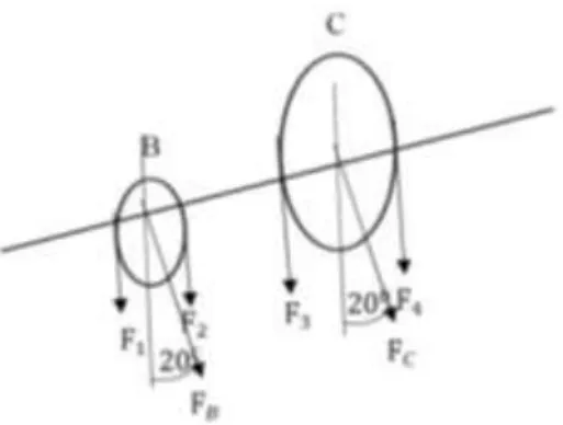
Determining the diameter of the shaft, first of all we need to know the forces acting on the shaft. For example, in the case of loading on horizontal axis with the pulley B and C below, force to the shaft can be illustrated by this Figure.
Figure 2.4 Shaft and Pulley
From Figure 2.4 above torque at B who work throughout BC can be calculated by the following equation.
T
B=
63000 x HP
n
[2.1]
where,
TB = torque at B who work throughout BC (lb.in)
HP = power works on pulley B (HP) n = rotating speed motor (rpm)
After the torque on the B and C obtained then calculate for the forces (F) on each pulley with torque moment by the following equation.
(F
1− F
2)
𝐷2
= T
B[2.2]
where,
TB = torque at B who work throughout BC (lb.in)
F1 F2 = force on the pulley B (lb)
D = diameter pulley (in)
From equation [2.1] and [2.2] will be known torque and the forces on the shaft, so that the figure would be like below.
Figure 2.5 Forces on The Shaft
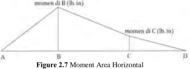
2.3.9 Calculation Reaction Force and Moment Area
Horizontal
After the forces along the axis is known, the next step calculate the reaction force on the horizontal direction of the shaft as in Figure 2.5.
From Figure 2.5 the value of AH and DH will obtained
by using sigma moment (M) and sigma forces (F). AH value obtained by the following equation.
𝑀𝐷= 0
𝐴𝐻(𝐴𝐷) − FBH(𝐵𝐷) − FCH(𝐶𝐷) = 0 [2.3]
where,
AH = horizontal force that works at point A (lb)
AD = distance from point A to D (in)
and DH value obtained by the following equation. 𝐹 = 0
𝐴𝐻− FBH− FCH+ 𝐷𝐻= 0 [2.4] where,
DH = horizontal force that works at point D (lb)
So, the diagram of moments will obtained like figure below.
Figure 2.7 Moment Area Horizontal
2.3.10 Calculation Reaction Force and Moment Area
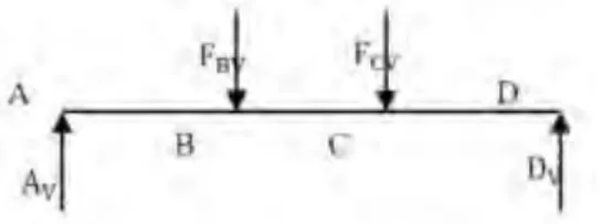
Vertical
The next step is to calculate the reaction force on the vertical direction of the shaft as in Figure 2.8
Figure 2.8 Vertical Reaction Force
From Figure 2.7 the value of AV and DV will obtained
by using sigma moment (M) and sigma forces (F). AV value obtained by the following equation.
𝑀𝐷= 0
𝐴𝑉(𝐴𝐷) − FBV(𝐵𝐷) − FCV(𝐶𝐷) = 0 [2.5]
where,
AV = vertical force that works at point A (lb)
AD = distance from point A to D (in)
and DV value obtained by the following equation. 𝐹 = 0
𝐴𝑉− FBV− FCV+ 𝐷𝑉= 0 [2.6]
where,
DV = vertical force that works at point D (lb)
So, the diagram of moments will obtained like figure below.
2.3.11 Calculation Shaft Dimension
After all forces that works on the shaft are calculated, the next step is determining the dimensions of the shaft. First, the maximum bending moments should to be known. To determine maximum moment in point B or point C of the Figure 2.9 can be calculated by the following equation.
MB= √𝐵𝑉2 + 𝐵𝐻2 [2.7]
where,
MB = bending moment maximum (lb.in)
𝐵𝑉 = bending moment vertical (lb.in)
𝐵𝐻 = bending moment horizontal (lb.in)
The result of equation [2.7] will get the maximum bending moment (Mmax) at point B or C. Afterthat, the equivalent twisting moment of the shaft can be calculated by equation [2.8] by entering maximum bending moment and maximum torque working on the system.
Te = √Mmax2+ Tmax2 [2.8]
where,
Te = equivalent twisting moment
Tmax = torsion moment maximum
Mmax = bending moment maximum
First, based on the theory of maximum shear stress which to find the shaft diameter based on the bending moment and torque that occur can use below equation.[8] Te = 16 x x d0 3 x (1 − k4 ) [2.9]
where,
=Sus
N [2.10]
Sus = ultimate shear stress material = 0,75 Sut N = safety factor (sf)
τ = torsional shear stress
k = ratio of inside dan outside shaft diameter
The result from the equation [2.9] and [2.10] will get the value of safety factor on the shaft diameter based on maximum shear theory.
Second, the analysis conducted by maximum normal stress theory happens to the shaft, it can be calculated by following equation.[8]
Me =1
2(Mmax + √Mmax
2+ Tmax2) [2.11]
where,
Me = equivalent bending moment Tmax = torsion moment maximum
Mmax = bending moment maximum
From the equation [2.11], the equivalent bending moment is equal to the following equation.
Me = 32 x b x do 3 x (1 −k4)
[2.12] where,
𝑏=
Sut N[2.13]
Sut = ultimate strength material N = safety factor (sf)
𝑏 = bending stressThe result from the equation [2.11] and [2.12] will get the value of safety factor on the shaft diameter based on maximum normal stress theory.
Third, the analysis subjected to fluctuating load, such as axial load, fluctuating torque, and bending moment on the shaft, for the equivalent twisting moment can be calculated by following equation.[8]
Te = √(Km x M)2+ (K t x T)2
and equal with Te = 16πx τ x do3x (1 − k4) [2.14]
where,
Te = equivalent twisting moment T = twisting moment
M = bending moment
Km = combined shock and fatigue factor for bending
Kt = combined shock and fatigue factor for torsion
For the equivalent bending moment can be calculated by following equation.
Me = 1
2[Km x M + √(Km x M) 2+ (K
t x T)2 ]
and equal with Me =
32 x b x do
3 x (1 −k4) [2.15]
where,
Me = equivalent bending moment T = twisting moment
M = bending moment
Km = combined shock and fatigue factor for bending
Kt = combined shock and fatigue factor for torsion
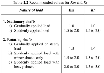
The following table shows the recommended values for Km and Kt.
Table 2.2 Recommended values for Km and Kt
Nature of load Km Kt
1. Stationary shafts
a) Gradually applied load b) Suddenly applied load
2. Rotating shafts
a) Gradually applied or steady load
b) Suddenly applied load with minor shocks only
c) Suddenly applied load with heavy shocks 1.0 1.5 to 2.0 1.5 1.5 to 2.0 2.0 to 3.0 1.0 1.5 to 2.0 1.0 1.5 to 2.0 1.5 to 3.0
Beside some of the methods above, in determining the diameter of the shaft, also can use the equation Distortion Energy Theory (Machine Design,
Deutcnman), the following equation [9].
2 / 1 2 2 4 3 4 3 1 32 r e syp m r e yp m o i o yp T S S T M S S M D D D N S [2.16] where,
Mm = bending moment average (lb in)
Mr = bending moment range (lb in)
Tm = torsion moment average (lb in)
Tr = torsion moment range (lb in)
S
e : Cr.Cs.Cf..f
K
1
S
es : Cr.Cs.Cf.. fsK
1
.S’s [2.18] where,Kf = concentration for bending stress Kfs = concentration for shear stress
Syp = yield point material (psi)
Ssyp = 0.5
Syp = yield point shear (psi)
Cr = reliability factor
Cs = size correction factor
Cf = surface correction factor
S’n = endurance limit
2.4 Bearing
A bearing is a machine element which support another moving machine element (known as journal). It constrains relative motion to only the desired motion and reduces friction between moving parts. It permits a relative motion between the contact surfaces of the members, while carrying the load. A little consideration will show that due to the relative motion between the contact surfaces, a certain amount of power is wasted in overcoming frictional resistance and if the rubbing surfaces are in direct contact, there will be rapid wear.
In order to reduce frictional resistance and wear and in some cases to carry away the heat generated, a layer of fluid (known as lubricant) may be provided. The lubricant used to separate the journal and bearing is usually a mineral oil refined from petroleum, but vegetable oils, silicon oils, greases etc., may be used.
The design of the bearing may, for example, provide for free linear movement of the moving part or for free rotation around a fixed axis; or, it may prevent a motion by controlling the vectors of normal forces that bear on the moving parts. Many bearings also facilitate the desired motion as much as possible, such as by minimizing friction. Bearings are classified broadly according to the type of operation, the motions allowed, or to the directions of the loads (forces) applied to the parts. The following are important from the subject point of view :
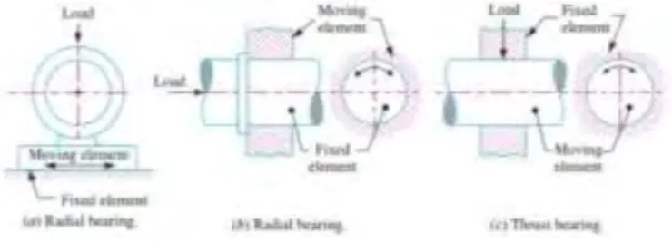
1. Depending upon the direction of load to be supported. The bearings under this group are classified as Radial bearings and Thrust bearings. In radial bearings, the load acts perpendicular to the direction of motion of the moving element as shown in Figure 2.9 (a) and (b). In thrust bearings, the load acts along the axis of rotation as shown in 2.9 (c).[8]
Figure 2.10 Radial and Thrust Bearing
A thrust bearing is used to guide or support the shaft which is subjected to a load along the axis of the shaft. Such type of bearings are mainly used in turbines and propeller shafts.
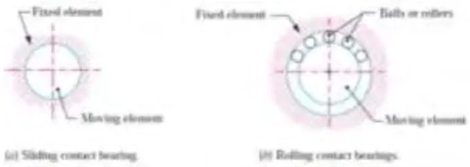
2. Depending upon the nature of contact. The bearings under this group are classified as Sliding contact
bearings and Rolling contact bearings. In sliding contact bearings, as shown in Figure 2.10 (a), the sliding takes place along the surfaces of contact between the moving element and the fixed element. The sliding contact bearings are also known as plain bearings. In rolling contact bearings, as shown in Figure 2.10 (b), the steel balls or rollers, are interposed between the moving and fixed elements. The balls offer rolling friction at two points for each ball or roller.
Figure 2.11 Sliding and Rolling Contact Bearing
2.4.1 Thrust Ball Bearing
The thrust ball bearings are used for carrying thrust loads exclusively and at speeds below 2000 r.p.m. At high speeds, centrifugal force causes the balls to be forced out of the races. Therefore at high speeds, it is recommended that angular contact ball bearings should be used in place of thrust ball bearings.
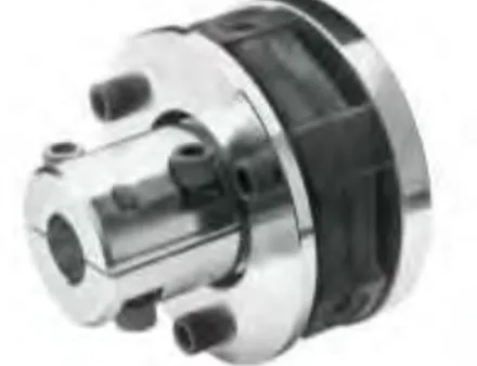
2.5 Shaft Coupling
A coupling is a device used to connect two shafts together at their ends for the purpose of transmitting power. Shafts are usually available up to 7 metres length due to inconvenience in transport. In order to have a greater length, it becomes necessary to join two or more pieces of the shaft by the coupling. Couplings do not normally allow disconnection of shafts during operation, however there are torque limiting couplings which can slip or disconnect when some torque limit is exceeded.
Shaft couplings are used in machinery for several purposes, the most common of which are the following :
- To provide for the connection of shafts of units that are manufactured separately such as a motor and generatorand to provide for disconnection for repairs or alternations.
- To provide for misalignment of the shafts or to introduce mechanical flexibility.
- To reduce the transmission of shock loads from one shaft to another.
- To introduce protection against overloads.
By careful selection, installation and maintenance of couplings, substantial savings can be made in reduced maintenance costs and downtime.
A shaft coupling also should have the requirements such as, it should be easy to connect or disconnect, can transmit the full power from one shaft to the other shaft without losses, hold the shafts in perfect alignment, can reduce the transmission of shock loads from one shaft to another shaft, and should have no projecting parts.
Shaft coupling are divided into two main groups, those are Rigid coupling and Flexible coupling. Rigid coupling is used to connect two shafts which are perfectly aligned. Types of rigid coupling are important from the subject point of view such as sleeve or muff coupling, clamp or split-muff or compression coupling, and flange coupling. Flexible coupling is used to connect two shafts having both lateral and angular misalignment. Types of flexible coupling are important from the subject point of view such as bushed pin type coupling, universal coupling, and oldham coupling. A flexible coupling is used so as to permit an axial misalignemnt of the shaft without undue absorption of the power which the shaft are transmitting.
Figure 2.13 Flexible Coupling
2.6 Material Properties
The mechanical properties can be interpreted as a response against the loading of a given material, such as force, torque, or a combination of both. In practices, loading on material devided into two, they are static loads and dynamic loads. The difference between them only in function of time where the static load is not influenced by the function of time while the dynamic loads influenced by the function of time.
2.6.1 Deformation
Deformation is a change in terms of dimensions and position of a material caused by natural circumstances or the excessive loads and work in the scale of time and space. Factors that control the deformation:
- Temperature and pressure in all directions - Speed of movement
Deformation is divided into two, namely, the elastic deformation and plastic deformation. Elastic deformation is a temporary change in shape. Changes will be lost when the force is removed. In other words, when the load is removed, then the object will return to forms and original size. Meanwhile, plastic deformation is a permanent change in shape, though the load is removed.[6]
2.6.2 Elasticity
Elasticity is a properties of an object or material to get return into the origin shape. Based on the elasticity, the material can be divided into elastic material and plastic materials. The plastic material is a material which can return to its original shape if the force acting on it removed. While the plastic material is a material that can not be returned to its original shape after the force acting on it removed.[6]
2.7 Material Mechanical Properties
Machine elements are very often made from one of the metals or metal alloys such as steel, aluminum, cast iron, zinc, titanium, or bronze. There are some important properties of materials as they affect mechanical design.
Strength, elastic, and ductility properties for metals, plastics, and other types of materials are usually determined from a tensile test in which a sample ofthe material, typically in the form of a round or flat bar, is clamped between jaws and pulled slowly until it breaks in tension. The magnitude of the force on the bar and the corresponding change in length (strain) are monitored and recorded continuously during the test. Because the stress in the bar is equal to the applied force divided by the area, stress is proportional to the applied force. The data from such tensile tests are often shown on stress-strain diagrams, such as in Figures 2.13. [6]
Figure 2.15 Typical Stress – Strain Diagram for Aluminium and
other metals having no yield point
2.7.1 Hardness
Hardness is defined as the resistance of a material to indentation/permanent penetration due to dynamic or static load.
2.7.2 Tensile Strength, s
uThe peak of the stress-strain curve is considered the ultimate tensile strength (su), sometimes called the ultimate strength or simply the tensile strength. At this point during the test, the highest apparent stress on a test bar of the material is measured. As shown in Figures 2.14, the curve appears to drop off after the peak. The apparent stress is computed by dividing the load by the original cross-sectional area of the test bar. After the peak of the curve is reached, there is a pronounced decrease in the bar's diameter, refened to as necking
down. Thus, the load acts over a smaller area, and the actual stress continues to increase until failure. [6]
2.7.3 Yield Strength, s
yYield strength is an overview of material ability to resist permanent deformation when used in structural usage involving mechanical loading such as pull, press, bending, or twisting, in other words, where there is a large increase in strain with little or no increase in stress. Figure 2.14 shows the stress-strain diagram form that is typical of a nonferrous metal such as aluminum or titanium or of certain high-strength steels. There is no pronounced yield point, but the material has actually yielded at or near the stress level indicated as sy. That point is determined by the offset method, in which a line is drawn parallel to the straight-line portion of the curve and is oft'set to the right by a set amount, usually 0.20% strain (0.002 in/in). The intersection of this line and the stress-strain curve defines the material's yield strength.[6]
2.7.4 Modulus of Elasticity
Modulus of elasticity (E) is the ratio of stress to strain. The greater the elastic modulus, the greater the stress to a particular strain. Comparison of tensile stress to tensile strain, for a given material, the same as the ratio of compression stress against compression strain. This comparison is called the modulus of strain or young modulus, denoted by E. [6] E =stress strain= compression stress compression strain E = Fn/A ∆l/lo= loFn A∆l [2.19]
E =
e[2.20]
where,
E = young modulus Fn = force (N)
A = cross sectional area of bar (m2) Δl = change in length of bar (m) lo = initial length (m)
2.8 Stresses
Stress is known when some external system of forces or loads act on a body, the internal forces (equal and opposite) are set up at various sections of the body, which resist the external forces. This internal force per unit area at any section of the body is known as unit stress or simply a stress. In the other words, reaction force or a force to return to its original form which occurs in a material and can not be calculated without involving force occurs.
2.8.1 Normal Stress
Normal stress is the intensity of the forces acting in perpendicular direction to the part that is stressed, and denoted by σ (sigma). When external forces acting on a block is parallel to the main axis and pieces of the block cross-section is constant, so the internal stress that produced and parallel to the axis is called axial force. In this figure below shows a block of material get some force.
Figure 2.16 Material Block
Stress that occurs in the material block can be written as, Stress = σ = 𝐴F [2.21] where, σ = stress (N/m2 ) F = force (N) A = section area (m2 )
2.8.2 Tensile Stress
Figure 2.17 Tensile Stress on Block The equation of tensile stress can be written as,
σ
t= F A= Fa A [2.22] where, σ𝑡 = tensile stress (N/m2) F = force (N) A = section area (m2 )2.8.3 Compressive Stress
The compressive stress occurs when a block was given force F opposite each other and located in one line. The equation of compressive stress can be written as,
Figure 2.18 Comprassive Stress on Block σD= F A= Fa A [2.23] where, σ𝐷 = compressive stress (N/m2) F = force (N) A = section area (m2 )
2.8.4 Shear Stress
Shear stress occurs when an object works with two forces in the opposite direction, perpendicular to the axis of the block, the force is not in one line but there is no moment on its section area.
Figure 2.19 Shear Stress on Block
In the figure above, two force F (P) are equal in opposite directions. Force F (P) worked evenly
distributed in cross section A. The shear stress can be calculated by,
τ =
F 𝐴 (N/m 2 ) [2.24] where,τ
= shear stress (N/m2) F = force (N) A = section area (m2 )2.8.5 Strain
Strain is the change in the size of the object because the forces in equilibrium compared to the original size. Strain can also describe as the degree of deformation. The deformation rate can be elongated, shortened, enlarge, shrink, and so on.
ɛ = ΔL [2.25] L where, ɛ = strain ΔL = change in length (m) L = initial length (m)
2.9 Load
Load is defined as any external force acting upon a machine part. The following four types of the load are important from the subject point of view :
1. Dead or steady load.
A load is said to be a dead or steady load, when it does not change in magnitude or direction, due to gravity fixed position. Which includes the dead load are the weight of the structure itself, other equipment on the structure and fixed.
2. Live or variable load.
A load is said to be a live or variable load, when it changes continually. Example : human and the equipment that can be moved.
3. Suddenly applied or shock loads.
A load is said to be a suddenly applied or shock load, when it is suddenly applied or removed.
4. Impact load.
A load is said to be an impact load, when it is applied with some initial velocity.
2.10 Safety Factor (sf)
Factor of safety is defined as the ratio of the maximum stress to the working stress. Mathematically,
Safety Factor = Maximum Stress Working or Design Stress
The selection of a proper factor of safety to be used in designing any machine component depends upon a number of considerations, such as the material, mode of manufacture, type of stress, general service conditions and shape of the parts. Before selecting a proper factor of
safety, a design engineer should consider the following points :
The reliability of the properties of the material and change of these properties during service,
The reliability of test results and accuracy of application of these results to actual machine parts,
The reliability of applied load,
The certainty as to exact mode of failure, The extent of simplifying assumptions, The extent of localised stresses,
The extent of initial stresses set up during manufacture, The extent of loss of life if failure occurs, and
The extent of loss of property if failure occurs.
2.11 Finite Element Analysis Method
Finite Element Analysis, commonly called FEA, is a method of numerical analysis. FEA is used for solving problems in many engineering disciplines such as machine design, acoustics, electromagnetism, soil mechanics, fluid dynamics, and many others. In mathematical terms, FEA is a numerical technique used for solving field problems described by a set of partial differential equations.[2] FEA is a powerful engineering analysis tool useful in solving many problems ranging from very simple to very complex. Design engineers use FEA during the product development process to analyze the design-in-progress. Time constraints and limited availability of product data call for many simplifications of computer models.
Finite Element Methode overcomes the disadvantages of traditional methode by providing a systematic procedue for the derivation of approximiation function over subregions of the domain.
Finite Element Methods have 3 basic feature :
1. Geomatrical complex domain of the problem is represent as a collection of geomatrical simple subdomains.
2. Each Finite Element derived using the basicidea that can be represented by a linear combination of algebraic polynomials.
3. Algrebaic relation among the undetermined coefficient.
When the FEM is applied to a specific field of analysis (like stress analysis, thermal analysis, or vibration analysis) it is often referred to as finite element analysis (FEA). An FEA is the most common tool for stress and structural analysis. Various fields of study are often related. For example, distributions of non-uniform temperatures induce non-obvious loading conditions on solid structural members. Thus, it is common to conduct a thermal FEA to obtain temperature results that in turn become input data for a stress FEA. FEA can also receive input data from other tools like motion (kinetics) analysis systems and computation fluid dynamics systems.
Figure 2.21 Finite Element Concept
The basic concept behind the FEM is to replace any complex shape with the union (or summation) of a large number of very simple shapes (like triangles) that are combined to correctly model the original part or an area
crudely meshed with linear and quadratic triangles. The smaller simpler shapes are called finite elements because each one occupies a small but finite sub-domain of the original part.
Figure 2.21 shows the finite element concept that from complex area than divided ito enclosed set of triangle that will integrared and sum the areas of the single small sub-domain into complex domain.
FEA converts scalar integrals to matrix expressions by assuming a spatial interpolation between the nodes of a typical element for items of interest, such as positions, displacements, velocities, or temperatures [2].
39
In order to solve the problem above, that will be used data analysis from literatures.
1. LITERATURE STUDY
Literature study was performed by collecting various references to support this final project. The media that will used is :
a. Books; b. Journals;
c. Engineering Report; d. Thesis
The primary concern for this literature study is transmission shaft for vertical axis turbine, design of shaft, calculation of shaft and other support component, and finite element methods.
2. SHAFT CALCULATION
At this stage will performed the calculation steps to determine the dimension of shaft. Before calculating, should be known the input parameter of turbine based on trials that have been conducted. The permanent variable is the power of turbine, 5 KW. The variation variable are 3 materials that will be used on shaft. The calculation steps are :
a. Determining the rotafional speed of the shaft.
b. Determining the power or the torque to be transmitted by the shaft.
c. Determining the design of the power-transmitting components or other devices that will be mounted on the shaft, and specify the required location of each device.
d. Specifying the location of bearings to support the shaft.
e. Determining the magnitude of torque that the shaft sees at all points.
f. Determining the forces that are exerted on the shaft, both radially and axially.
g. Resolving the radial forces into components in perpendicular directions, usually vertically and horizontally.
h. Solving for the reactions on all support bearings in each plane.
i. Producing the complete shearing force and bending moment diagrams to determine the distribution of bending moments in the shaft.
j. Selecting the material from which the shaft will be made, and specify its condition
3. MODELING
At this stage, modeling will perform using solid modeling Computer Aided Engineering (CAE). Dimension of shaft is based on shaft calculation and specification determined.
4. RUNNING SIMULATION
Running simulation will performed by giving spesific rotating speed to the vertical axis turbine shaft and the others input data for material and properties to perform meshing and analyze the stress, strain, deformation of vertical axis turbine shaft. This final project will perform simulation using Finite Element Analysis Methods.
5. DATA ANALYSIS
Data from literature study and running simulation such as stress, strain, safety factor, and deformation will analyze to know the strength analysis of vertical axis turbine shaft using FEAM that implemented in Solidwork Simulation.
6. OUTPUT ANALYSIS
The output data from this final project based on Finite Element Analysis Methods is Stress, Strain, Safety Factor, and Displacement of Vertical Axis Turbine Shaft.
7. CONCLUSION & REPORTING
At the end of stages will inform about the strength analysis of vertical axis turbine shaft and also the dimension and its spesification, as a transmission shaft for mechanical transmission system that capable for 5 kW capacity on ocean current power plant
45
4.1
Analysis of Ocean Current Platform Concept
Ocean currents platform are offshore building convert ocean currents into electric energy with utilizing the rotation of the ocean current turbine. There are several types of platforms for ocean current power plant. One of the types is TLP (Tension Light Platform). TLP is a platform with a simple type of box. Figure 4.1 shows the concept of this ocean current platform.
Figure 4.1 Tension Light Platform
Determining the type of platform used will require consideration based on certain parameters. The one of parameters is power that can be generated. When using a platform, the number of turbines that can be used on a platform will determine the amount of power generated. If on some platform have the same number of turbines, so the next thing should be reviewed is the result of the current in the area around it. Spacing of each turbine is also
influental. Tension Leg Platform (TLP) can use three turbines on the platform and the spacing of three turbines are not too close. The direction of the ocean currents that uncertainty will also affect the condition of the platform. When viewed from many aspects, the best choice can be used is TLP because TLP can receiving current from all directions.
4.2
Analysis of Vertical Axis Turbine Concept
Vertical axis turbine (VAT) has a rotational axis that is perpendicular to the direction of fluid flow. In the application at sea, vertical turbine can transmit torque directly to the surface of the water without complex transmission systems under the sea. The characteristic of this turbine has a very high starting torque that can start the turbine rotation spontaneously without another help. Turbine that used in this concept is VAT with Darrieus types. Based on the previous research by CFD (Computational Fluid Dynamics), airfoil type for turbine that chosen is NACA 0018 with simetry airfoil and 9 blades.
NACA 0018 airfoil type is best for NACA series and commonly used for Darrieus turbine because this foil has a thickness to chord ratio is relatively high, so it has good strength to resist bending. Furthermore, NACA 0018 has the best characteristics for vertical axis turbine of ocean currents.
4.3
Vertical Axis Turbine (VAT) Shaft
Plan of vertical axis turbine shaft is arranged by a series of three shafts having a length respectively 3.3 m, 2 m and 2 m and connected by flexible coupling are shown in Figure 4.3. There is no provision and calculation to determine the length of shaft.
The calculation of shaft diameter can be determined by this following equation. D = [32N π √[ KtM S′n] + 3 4[ T Sy] 2 ] 1 3 [4.1] From that equation, the amount of torsion and bending moment on the shaft should be known.
4.4
Designing of Vertical Axis Turbine Shaft
4.4.1
Shaft Material
The variation variable of this research is the material. It will compare three different materials and the form of the shaft, round bar (solid) or hollow. The materials that used to compare are :
1. High Tensile Steel AISI 4140
2. Medium Tensile Carbon Steel AISI 1045 3. Stainless Steel AISI 316.
From the following result of calculation and analysis, the shaft material that recommended to be used is High Tensile Steel AISI 4140 that have 1% chromium-molybdenum medium hardenability. The ultimate tensile strength (su) of the material is 850 – 1000 Mpa
and the yield strength (sy) is 665 Mpa.
This shaft material chosen by the reason, the chromium content provides good hardness penetration and the molybdenum content ensures uniform hardness and high strength. Beside that, its also good ductility and good wear resistance.
4.4.2
Shaft Design Calculation
Below is the calculation process to design a turbine shaft.
1) First, determining the turbine paramater. This
parameter based on trials that have been conducted. Torsion (T) = 1326 Nm
Rotating Speed = 36 RPM = 3,768 rad/s
R Turbine = 0.8 m
Ft = 1326
0,8 = 1657,5 N
Power = 5000 W
2) Determining the maximum torsion and bending
moment on the shaft.
Force (Ft) that appear on the turbine, its effect on the shaft 3,3 meter as bending moment. Based on the analysis performed by using MD Solid, it produces the analysis results of force distribution and moment distribution as following figure.
Figure 4.4 Force on Turbine Shaft
Figure 4.6 Moment Diagram
The Figure 4.6 shows that maximum bending moment on shaft 1 is 2652 Nm, while based on trial of turbine get the maximum torque 1326 Nm. Below is the analytical calculation by using Three Moment Equation Theory. The theory is used to find excessive moment in many supports. The equation also called repetitive formula to find every three moment that is undefined.
LLML+ 2 (LL+ IL IRLR) MC+ IL IRLRMR= −PLab (1 + a LL) [4.2] where,
𝐿𝐿 = distance on left side from C
𝐿𝑅 = distance on right side from C
𝑀𝐿 = moment on life side
𝑀𝐶 = moment on center
𝑀𝑅 = moment on right side
𝑃𝐿 = force on life side
𝑃𝑅 = force on right side
𝐼
𝑅=
𝐼
𝐿= inertia moment (constant)
LLML+ 2 (LL+ IL IRLR) MC+ IL IRLRMR= −PRa′b′ (1 + a LL) [4.3]
The equation [4.2] is for calculate for finding maximum moment on left side. Otherwise, equation [4.3] for finding maximum moment on right side. The detail calculation for this vertical
axis turbine shaft using three moment equation is as following.
𝑀𝐴= −1657,5 . 1,6 = −2652 𝑁𝑚
Three moment equation for ABC, AB left side and BC right side
1,5 MA+ 2 (1,5 + 0,4)MB+ 0,4 MC= 0
(0 because there is no other force on left side or right side of B, and also C, D, E, F)
1,5 . 2652 + 3,8 MB+ 0,4 MC= 0
3,8 MB+ 0,4 MC= −3978 ...(1)
Three moment equation for BCD, BC left side and CD right side
0,4 MB+ 2 (0,4 + 1,6)MC+ 1,6 MC= 0
0,4 MB+ 4 MC+ 1,6 MC= 0 ...(2)
Three moment equation for CDE, CD left side and DE right side
1,6 MC+ 2 (1,6 + 0,4)MD+ 0,4 ME= 0
1,6 MC+ 4 MD+ 0,4 ME= 0...(3)
Three moment equation for DEF, DE left side and EF right side, MF = 0 because on the end of shaft.
0,4 MD+ 2 (0,4 + 1,8)ME+ 1,8 MF= 0
0,4 MD+ 4,4 ME= 0...(4)
The completion of equation (1), equation (2), equation (3), and equation (4) by doing elimination and substitution will result :
MA= −1657,5 . 1,6 = −2652 Nm
MC= 126,44 Nm MD= −51,04 Nm ME= 4,64 Nm MF= 0
And then, it can be defined the reaction force of each section. ME = 4,64 Nm ΣME= 0 (clockwise) → 4,64 − 1,8 RF= 0 ∴ RF= 2,58 N MD = −51,04 Nm ΣMD= 0 (counterclockwise) → −RE(0,4) + 2,58 . 2,2 = 0 ∴ RE= −14,19 N MC = 126,44 Nm ΣMC = 0 (counterclockwise) → RD . 1,6 + 14,9 . 2 – 2,58 . 3,8 = 0 ∴ RD= 11,61 N MB = −1060,24 Nm ΣMB = 0 (counterclockwise) − RC . 0,4 − 11,61 . 2 – 14,19 . 2,4 + 2,58 . 4,2 = 0 ∴ RC= − 116,1 N
3) Determining shaft diameter and its factor of safety The variable of this research will compare the shaft was made by hollow bar and round bar (solid shaft). The process of analyzing the safety factor on the shaft can be done based on the following theories.
a) Maximum shear stress theory
b) Maximum normal stress theory
c) Shafts subjected to fluctuating loads
Below is the example of detail calculation for
Hollow Shaft by three theories. Hollow shaft
diameter is planned of inside diameter (di) = 0,035 m and outside diameter (do) = 0,05 m and the material is High Tensile Steel AISI 4140 with ultimate tensile strength (su) of the material is 850 –
1000 MPa and the yield strength (sy) is 665 MPa.
a) Maximum Shear Stress Theory
Maximum shear stress induced due to twisting moment (torque or shear loading).
Known :
Mmax = 2652 Nm Tmax = 1326 Nm
The equivalent twisting moment (Te) can be calculated by :
Te = √Mmax2+ Tmax2 [4.2]
Te = √26522+ 13262
Te = 2965,03 Nm
Next, the value of safety factor can be determined by :
Te =
16 x x do
where,
=Sus
N [4.4]
Sus = ultimate shear stress material
= 0,75 Sut
N = safety factor (sf)
= torsional shear stress
k = ratio of inside and outside shaft
diameter = di /do So, Te = 16 x Sus N x d0 3 x (1 −k4 ) 2965,03 =3,14 16 x 0,75.850000000 N x 0,05 3 x (1 −0,035 0,05 4 ) ∴ N = 4,008
b) Maximum Normal Stress Theory
Maximum normal stress induced due to bending moment (tensile or compressive) or its due to the forces acting upon machine elements like gears, pulleys etc. as well as due to the weight of the shaft itself.
Known :
Mmax = 2652 Nm Tmax = 1326 Nm
The equivalent bending moment (Me) can be calculated by : Me =1 2(Mmax + √Mmax 2+ Tmax2) Me =1 2(2652 + √2652 2+ 13262) Me = 2808,5 Nm
Next, the value of safety factor can be determined by :
Me =
32 x
x do3 x (1 − k4)
![Figure 2.1 Ocean Current Platform [10]](https://thumb-ap.123doks.com/thumbv2/123dok/4067471.3036555/20.629.210.441.102.278/figure-ocean-current-platform.webp)
![Table 2.1 Mechanical Properties of Steels Used for Shafts [8]](https://thumb-ap.123doks.com/thumbv2/123dok/4067471.3036555/23.629.169.542.104.357/table-mechanical-properties-steels-used-shafts.webp)