DATA COMMUNICATION AND
COMPUTER NETWORKS
Written by Dr.P.Premchand
Dept. of CSE, College of Engineering, Osmania University, Hyd 500007
Edited by
K.Goverdhan Naidu
Dedicated to the fond memories of Late Prof. S.V.L.N Rao garu, my guruji, retired Professor IIT Kharagpur
who
taught me the courage in leading the academic life. and
Late Prof. K.N.Raju garu,
subject in a simple and lucid manner. The subject has been divided into 6 units, each unit targeted to cover basic principles and topics of fundamental importance. This book gives a clear insight to the reader regarding various aspects of the subject. In a competitive world like this, understanding these technologies is very essential.
The summary of the book is as follows:-
UNIT 1 Data communications: Covers the different types of communications which have evolved during the course of the time and techniques used to transmit the data.
Unit 2 Network Topology: Covers the different types of networks and the various types of network topologies.
Unit 3 LAN Components: This unit emphasizes on the LAN components like LAN Card, LAN cables, Hubs/switches etc in detail. Unit 4 Communication Hardware: This unit gives an account of the various communication hardware existing today
Unit 5 Network environment This unit stresses on understanding UNIX and WIN NT operating system.
Unit 6 Network and Web applications: This unit covers network and Web Applications like email, FTP, TELNET etc in detail.
Contents
1. Data Communications
1.1 Data Communication Model 1
1.2 Signal Conversions 3
1.3 Analog signal 3
1.4 Waveforms of different parameters 4
1.5 Bandwidth 5
1.6 Noise 6
1.7 Channel Capacity 6
1.8 Types Of Communications 7
1.9 Modes of transmission 9
2.4Metropolitan Area Network (MAN) 24
4. Communication Hardware
4.1Modem 44
4.2VSAT 46
4.3FTDMA 46
4.4Direct PC 48
4.5IP advantage 49
4.6Asynchronous Transfer mode 51
5. Network Environment
5.1Network Operating System 54
5.2Features of Network Operating System 54
5.3UNIX 55
5.4Domain Name Servers 61
5.5Simple Network Management Protocol 62
5.6Boot protocol 62
5.7Sockets 62
5.8Networking Commands 62
5.9System Administrator 65
5.10 Windows NT Server 67
6. Network and Web Applications
6.1E-mail 80
6.2File Transfer Protocol 84
6.3TELNET 87
6.4Gopher 89
6.5Messaging/Instant Messaging 90
6.6Web Browsers 92
6.7 Internet Explorer Basics 92
6.8Netscape Navigator 100
6.9Netscape Communicator 101
1. Data Communications
Communication is defined as transfer of information, such as thoughts and messages between two entities. The invention of telegraph, radio, telephone, and television made possible instantaneous communication over long distances.
In the context of computers and information technology (IT), the data are represented by binary digit or bit has only two values 0s and 1s. In fact any thing the computer deals with are 0s and 1s only. Due to this it is called discrete or digital. In the digital world messages, thoughts, numbers.. etc can be represented in different streams of 0s and 1s.
Data communications concerns itself with the transmission (sending and receiving) of information between two locations by means of electrical signals. The two types of electrical signals are analog and digital. Data communication is the name given to the communication where exchange of information takes place in the form of 0s and 1s over some kind of media such as wire or wireless. The subject-Data Communications deals with the technology, tools, products and equipment to make this happen.
Entire data communication system revolves around three fundamental concepts.
• Destiny: The system should transmit the message to the correct intended destination. The destination can be another user or another computer.
• Reliability: The system should deliver the data to the destiny faithfully. Any unwanted signals (noise) added along with the original data may play havoc!
• Fast: The system should transmit the data as fast as possible
within the technological constraints. In case of audio and video data they must be received in the same order as they are produced without adding any significant delays.
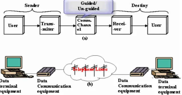
1.1 Data Communication model
• User: There will be a source that generates the message and a transducer that converts the message into an electrical signal. The source can be a person in front of a microphone or a computer itself sending a file. The user terminal is known as data terminal equipment (DTE).
• Transmitter: Can be a radio frequency modulator combining the
signal coming out of the data equipment terminal. Here the radio frequency is acting as the carrier for the data signal. Or in case of direct digital transmission the transmitter can be Manchester encoder transmitting digital signals directly.
• Communication channel: Can be guided media (twisted pair,
coaxial cable, fiber optic.,) or unguided media (air, water .,). In both the cases communication is in the form of electro magnetic waves. With guided media the electro magnetic waves are guided along a physical path. Unguided media also called wireless the transmitting electro magnetic waves are not guided along with a physical path. They are radiated through air/vacuum/water., etc.
• Receiver: The receiver amplifies the received signals removes
any unwanted signals (noise) introduced by the communication channel during propagation of the signal and feeds to the destiny. • Destiny: The user at the other end finally receives the message
through the data terminal equipment stationed at the other side.
Data Communications 3
Fig 1.1 (b) shows a typical dial-up network setup. The data communication equipment (DCE) at the transmitting end converts the digital signals into audio tones (modulation) so that the voice grade telephone lines can be used as guided media during transmission. At the far end the receiving audio tones, they are converted back to digital signals (Demodulation) by the data communication equipment (DCE) and fed to the far end data terminal equipment (DTE).
1.2 Signal conversions
There are two types of signals analog and digital. All naturally available signals are analog in nature. In data communications these signals are converted into digital form by means of A-to-D converters
(analog to digital converters).
The following figure illustrates the analog output of microphone and subsequent conversion into its digital counter part by A-to-D converter.
Fig 1.2.1 Example of analog and digital signal
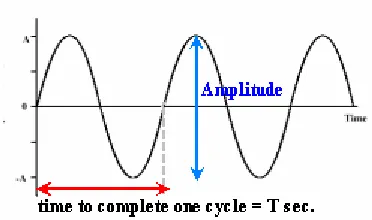
1.3 Analog signal.
Fig 1.3.1 A simple sine wave and its parameters.
to complete one cycle is called time period and measured in seconds. The reciprocal of time period is frequency and its unit is cycles per second(c/s) or Hz (Hertz).(See Fig.1.2)
1.4 Wave forms of different parameters
The following figures show the signals with different parameters and their inter-relationship
Fig 1.4.1 Different wave forms with different parameters
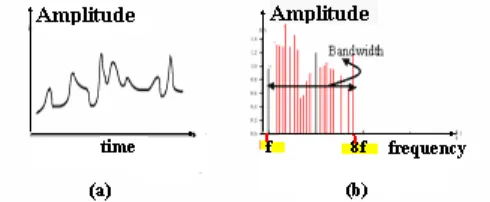
1.5 Bandwidth
Mathematically it can be shown that any complex waveform is a made of sine waveforms of different amplitudes and frequencies with varying phase relationships amongst each other.
Fig 1.5.1 (a) An analog signal(b) Its various frequency components.
Data Communications 5
analog systems the difference between highest frequency to lowest frequency component is called bandwidth (here it is 8f~f = 7f).
Bandwidth merely specifies a range of frequencies, from the lowest to the highest, that the channel can carry or that are present in the signal. It is one way of describing the maximum amount of information that the channel can carry. Bandwidth is expressed differently for analog and digital circuits. In analog technology, the bandwidth of a circuit is the difference between the lowest and highest frequencies that can pass through the channel. Engineers measure analog bandwidth in kilohertz or megahertz.
Rate of transmission = (bits per second)
Fig 1.5.2 Relation between bit time and rate
In data communication, the bandwidth is the amount of information that can pass through the channel or medium. Engineers measure digital bandwidth in bits, kilobits, or megabits per second. The kilohertz of an analog bandwidth and the kilobits per second of digital bandwidth for the same circuit are not necessarily the same and often differ greatly.
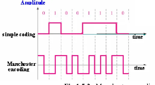
Fig 1.5.3 Manchester encoding
In principle digital signals require a large bandwidth (theoretically infinite!). The medium has to be of better quality to send digital signals. Most LANs use Manchester encoding because of its self-synchronizing property. Otherwise separate clock signals were to be transmitted along with data in order to inform about sender’s transmission clock. In Manchester encoding there is a transition in each bit interval and this property serves as clock also.
1.6 Noise
In any type of communication, noise is the biggest impairment. The received signal at the receiver end will consist of transmitted message plus additional unwanted signal that are inserted somewhere between transmitter and receiver distorting the message.
There are several types of noise sources, which can abruptly affect the quality of reception signal. The following are some of them
• Thermal noise: Due to thermal agitation of electrons.
Present in all electronic devices and is the function of temperature.
• Impulse noise: Due to electromagnetic interference
(EMI). They may be present in power lines, or in nature (lightning.. etc)
• Delay distortion: Due to non-uniform velocities of
signals of different frequencies traveling in a guided media. Various frequencies of a message signal will arrive at different delays resulting in distortion.
1.7 Channel capacity
The maximum rate at which data can be transmitted over a communication channel under given conditions is referred as the channel capacity.
There are four parameters involved in the evaluation of channel capacity.
• Data rate: The rate at which data can be transmitted. Measured in bits per second
• Bandwidth: The bandwidth of the transmitted signal. Measured
Data Communications 7
• Noise: The average level of unwanted signals over
communication path. Expressed as the ratio between signal and noise.
• Error rate: The rate at which error can occur.
Then the channel capacity (in cycles per second) according to Shannon’s theorem is given by
C = B log2 (1+SNR)
Where
• C in Cycles per second and this is error free capacity • B is the bandwidth in Hertz.
• SNR = 10 log10 (Signal power/Noise power)
Normally this theorem represents maximum channel capacity. Actual values maybe much less than as given by the formula. One reason for this is the SNR ratio. The SNR ratio assumes only white noise (thermal noise) where as other noise like impulse noise, attenuation noise and delay noise are not taken into account.
1.8 Types of communication
Based on the requirements, the communications can be of different types:
• Point- to-point communication: In this type, communication
takes place between two end points. For instance, in the case of voice communication using telephones, there is one calling party and one called party. Hence the communication is point-to-point.
• Point-to-multipoint communication: In this type of
• Broadcasting: In a broadcasting system, there is a central location from which information is sent to many recipients, as in the case of audio or video broadcasting. In a broadcasting system, the listeners are passive, and there is no reverse communication path.
• Simplex communication: In simplex communication,
communication is possible only in one direction. There is one sender and one receiver; the sender and receiver cannot change roles.
• Half-duplex communication: Half-duplex communication is
possible in both directions between two entities (computers or persons), but one at a time. A walkie-talkie uses this approach. The person who wants to talk presses a talk button on his handset to start talking, and the other person’s handset will be in receive mode. When the sender finishes, he terminates it with an over message. The other person can press the talk button and start talking. These types of systems require limited channel bandwidth, so they are low cost systems.
• Full-duplex communication: In a full-duplex communication
system, the two parties the caller and the called can communicate simultaneously, as in a telephone system. However, note that the communication system allows simultaneous transmission of data, but when two persons talk simultaneously, there is no effective communication! The ability of the communication system to transport data in both directions defines the system as full duplex.
Data Communications 9
1.9 Modes of transmission
When we talk of data communication we are primarily concerned with serial transmission although other types of transmission does exists. In serial transmission the data is transmitted bit by bit as a stream of 0s and 1s. Protocols are implemented for these types of transmissions so that the communication takes place in a well-defined manner. Protocols are mutually agreed set of rules and are necessary because the format of transmission should be understood by the receiver
The following key factors have to be observed regarding serial transmission:
• Timing problem: There should be some mechanism to know
when the bit has arrived and at what rate the next bit is going to arrive at the serial input terminal of the receiver. We will see this can be accomplished in two ways.
• Error detection: Provision should be made (during transmission itself) to verify the integrity of the received data. Like parity, checksum bits.
• Error correction: Ability to correct the data in case of
corrupted data reception.
Timing problems require a mechanism to synchronize the transmitter and receiver. There are two approaches regarding transmission of serial data.
• Asynchronous transmission
• Synchronous transmission
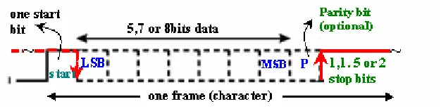
1.9.1 Asynchronous transmission
Fig 1.9.1 Asynchronous data format
• In a steady stream, interval between characters is uniform (length of stop element can be 1,1.5 or 2 stop bits - as programmed earlier)
• In idle state, receiver looks for transition 1 to 0 (start signal)
• Then samples next five, seven or eight intervals (as programmed earlier) Timing only needs maintaining within each frame (bit level).
• Looks for parity (if programmed earlier)
• Then looks for next 1 to 0 for next frame
• Simple
• Cheap. Minimum hardware & software requirement to
impliment.
• Overhead of 2 or 3 bits per frame (~20%)
• Good for data with large gaps in between each frame
(keyboard, low speed data..)
1.9.2 Synchronous transmission
In Synchronous transmission a block of data in the form of bits stream is transferred without start / stop bits. The block can be of any arbitrary length. In order to establish synchronization with remote computer the transmitter transmits synch pulses initially. When the receiver locks to the transmitter’s clock frequency a block of data gets transmitted. See fig.1.9.2
The Characteristics are as follows
• Block of data transmitted without start or stop bits • Initially synch pulses are transmitted (Clocks must be
Data Communications 11
• Can use separate clock line (In that case synch pulses are not needed!)
• Good over short distances
• Subject to impairments
• Embed clock signal in data (Manchester encoding)
• Carrier frequency (analog) is used • Need to indicate start and end of block
• Use preamble and post amble (to leave sufficient space between blocks)
• More efficient (lower overhead) than asynchronous transmission.
Fig 1.9.2 The synchronous frame format
1.10 Multiplexing
By Multiplexing different message signals can share a single transmission media (The media can be guided or unguided). All they need is they should either differ in their frequency slot or wavelength slot or in time slot.
1.10.1 Frequency domain multiplexing (FDM)
Fig 1.10.1 Frequency domain multiplexing
The Radio /TV broadcasting are the best examples for frequency domain multiplexing. Several individual stations broadcast their programs in their own allotted frequency band sharing the same unguided media. The receiver tunes his set according to his choice. The cable TV network is another example of Frequency domain multiplexing employing guided media.
1.10.2 Wavelength division multiplexing (WDM)
Wavelength division multiplexing is a type of FDM scheme used in fiber optical communications where various wavelengths of infrared light are combined over strands of fiber.
Optical communication with few exceptions are digital since light transmitters and receivers are usually poorly suited for analog modulation.
Data Communications 13
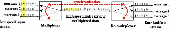
1.10.3 Time domain multiplexing (TDM)
A type of multiplexing where two or more channels of information are transmitted over the same media by allocating a different time interval ("slot" or "slice") for the transmission of each channel. The channels take turns to use the media. Some kind of periodic synchronizing signal or distinguishing identifier is usually required so that the receiver can tell which channel is which.
A typical practical setup combines a set of low-bit-rate streams, each with a fixed and pre-defined bit rate, into a single high-speed bit stream that can be transmitted over a single channel.
The main reason to use TDM is to take advantage of existing transmission lines. It would be very expensive if each low-bit-rate stream were assigned a costly physical channel (say, an entire fiber optic line) that extended over a long distance.
Fig. 1.10.3 Time division multiplexing.
1.11 Network Models
When people to people, machines to machines started communicating with each other the networking technology started picking up. Different vendors started manufacturing their proprietary configurations. In order to communicate systems with heterogeneous configurations there was a need for standardization. TCP/IP(Transmission Control Protocol / Internet Protocol) is the oldest one and has become defacto standard for all networks. OSI model is much more refined and let us hope all future models will be based on this.
models were suggested out of which the Internet model is widely accepted. Later OSI (open systems interconnection) was developed as a theoretical model. Studying OSI model gives better perception of the various intricacies involved in data communication and networking.
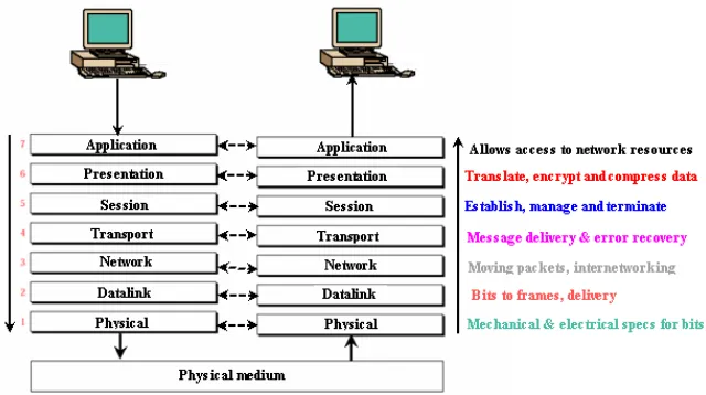
1.11.1 The OSI Model
It has seven layers. They are separate but related. Each layer has well defined tasks and provides services to the corresponding lower layer while in transmission. In receiving mode the lower layer provides the necessary services to the upper layer. Any changes in one layer should not require changes in other layers.
This kind of standardization allows communication across all types of computers.
Fig 1.11.1 The OSI Layers and their functions
Easy to remember these layers!……… Please Do Not Touch Shiva’s Pet Alligator
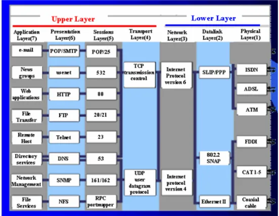
The Seven Layers of OSI and their conceptual services -
Data Communications 15
Services – e-mail, news groups, web applications, file transfer, remote host, directory services, network management, file services
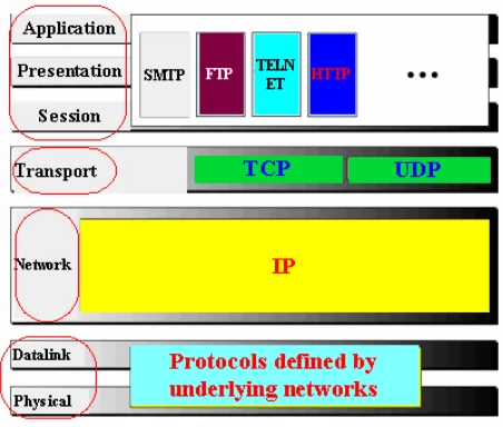
• Presentation - (layer 6) Translates data into a form usable by the application layer. The redirector operates here. Responsible for protocol conversion, translating and encrypting data, and managing data compression. messages are sent between layers Services – POP, SMTP (e-mail, Post office protocol, Simple Mail Transfer Protocol), Usenet (for news groups), HTTP (hyper text transfer protocol for web applications), FTP, TFTP (File transfer protocol, trivial FTP for file transfer), Telnet (Terminal Network, A general purpose program enabling remote login into some other computer and function as if it is directly connected to that remote computer), Domain name server (finding ip addresses for domain names), SNMP (Simple Network Management Protocol).
• Session - (layer 5) Allows applications on connecting systems to standard ports & establish a session. Provides synchronization between communicating computers. Messages are sent between layers
Services – Various port numbers are POP(25), USENET(532),
HTTP(80), FTP(20/21), Telnet(23), DNS(53), SNMP(161/162) etc..
• Transport - (layer 4) Responsible for packet handling. Ensures
error-free delivery. Repackages messages (while receiving), divides messages into smaller packets (while transmitting), and handles error handling. segments of message fragments are sent between layers
Services - TCP - connection-oriented communication for
applications to ensure error free delivery;
UDP - connectionless communications and does not guarantee packet delivery between transfer points
• Network - (layer 3) Translates system names into addresses.
managing network traffic problems, packet switching, routing, data congestion, and reassembling data. Datagrams are sent between layers.
Services - Software & hardware addresses and packet routing between hosts and networks (IP). Two versions IP4(32 bits) & IP6(128 bits)
• Data link - (layer 2) Sends data from network layer to physical layer. Manages physical layer communications between connecting systems. Data frames are sent between layers
Services – SLIP/PPP, 802.2 SNAP, Ethernet
• Physical - (layer 1) Transmits data over a physical medium.
Defines cables, cards, and physical aspects. Data bits are sent.
Services - ISDN, ADSL, ATM, FDDI, CAT 1-5, Coaxial cable
Fig 1.11.2 The OSI Model an their example services
1.11.2 The Internet model
Data Communications 17
• Application Layer: Most of the responsibilities of the three top most layers of OSI model are in application layer of Internet model. The services are as depicted in the fig.
• Transport Layer: It has two protocols. TCP (Transmission
Control Protocol) and UDP (User Datagram Protocol). TCP is a reliable protocol that allows two application layers to converse with each other. While transmitting it divides the stream of characters into manageable segments. While receiving it creates stream of characters for application layer from received segments from network layer. Its function is much more than as depicted in OSI model. Some of the responsibilities of OSI’s session layer are dissolved into Internet model’s transport layer.
The other protocol UDP is a simpler protocol. It ignores some of the duties of the transport layer defined in OSI model. It is used when fast delivery of packets is needed without worrying much about error control.
• Network Layer: The main protocol is IP (Internet Protocol) is
responsible for creating network layer packets called IP datagrams. The datagrams travel network to network or LAN to WAN and the packets may reach out of sequence. It is the responsibility of upper layers to put them into proper order.
• Datalink & physical Layer: The Internet model does not discuss much about these layers making this protocol machine independent to a large extent. It is left to the user to choose the proper standard or protocol according to what they desire.
Summary:
Data communications concerns itself with the transmission (sending and receiving) of information between two locations by means of electrical signals. The media can be guided (physical) wires or unguided (radio links). The two types of electrical signals are analog and digital.
Analogue signals have three main characteristics which define them, being amplitude, frequency and phase. Speech is an example of an analogue signal.
In data communications the channel bandwidth is represented in bits/sec and Shannon’s theorem imposes a bandwidth restriction for low noise transmission.
Many aspects of data transmission are covered in this unit. There are six types of communication point-point, point-multipoint, broadcast, simplex, half duplex and full duplex.
Two modes of transmission are synchronous and asynchronous. Protocols (mutually agreed set of rules) are necessary to implement this type of serial communication system.
Several digital signals can be transmitted simultaneously over guided/unguided media using three basic techniques time domain multiplexing, frequency domain multiplexing and wavelength division multiplexing.
When people to people, machines to machines started communicating with each other- the networking technology started picking up. Different vendors started manufacturing their proprietary configurations. In order to communicate systems with heterogeneous configurations there was a need for standardization. TCP/IP is the oldest standard and has become defacto standard for all networks. OSI model is much more refined and let us hope all future models will be based on this.
Short questions:
1). The three parameters associated with analog signal are: 2). Furnish an example for guided media:
3). According to Shannon’s if bandwidth increases noise……. 4). The example for simplex transmission…….
Data Communications 19
6). Thermal noise is due to ……..
7). On telephone lines digital signals are transmitted as ……….. 8). State the practical use of a multiplexer
9). What are the seven layers of OSI 10). State the services in sessions layer
Long questions:
1). Define data communication. How it is different from other types of communication?
2). Draw the block diagram of typical data communication model and explain its constituents.
3). Explain the term- bandwidth. How analog bandwidth is different from data communication bandwidth
4). Enumerate different types of communication. Site examples for each of them?
5). What is noise? How many types of noise are there? 6). Discuss in detail about multiplexing.
7). What are the factors involved in serial transmission? 8). Why Protocols are needed?
9). Explain TCP/IP model
A network is a set of equipments (often referred as data terminal equipment / DTE, or simply terminals or nodes ..) connected by a communication channel, which can be either guided/unguided media. DTE equipment can be a computer, printer or any device capable of sending and/or receiving data generated by other nodes on the network.
2.1 Why networking?
• Sharing of hardware
Computer hardware resources Disks
Printers..
• Sharing of software
Multiple single user licenses are more expensive than multi-user license.
Easy maintenance of software
• Sharing of information
Several individuals can interact with each other Working in groups can be formed
• Communication
internet telephony audio conferencing video conferencing
• Scalability
Individual subsystems can be created and combine it into a main system to enhance the overall performance.
• Distributed systems
Network Topologies 21
2.2 Types of networks
2.2.1 Point to point
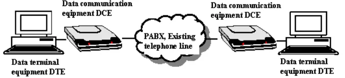
Figure 2.1.1 shows a communication system used to interconnect two computers. The computers output electrical signals directly through the serial port. The data can be passed directly through the communication medium to the other computer if the distance is small (less than 100 meters).
Fig.2.2.1 PC to PC communication using com ports
Figure 2.1.2 shows a communication system in which two PCs communicate
with each other over a existing say local telephone exchange (PABX) network. In this system, we introduced device called DTE data terminal equipment. The example here for DTE is modem (modulator-demodulator) connected at both ends. The PCs send digital signals, which the modem converts into analog signals and transmits through the medium (copper wires). At the receiving end, the modem converts the incoming analog signal into digital form and passes it on to the PC.
2.3 Local Area Network (LAN)
A LAN is a local area network that is a small collection of computers in a small geographic area of less than couple of kilometers and is very fast in data transfer. Depending on technology implementation a LAN can be as simple as two PCs and a printer got connected in a small office or it can extend through out an organization and include multimedia (text, voice, video) data transfers.
The LANs may be configured in many ways. The peer-to-peer configuration is the simplest form. In this configuration computers are connected together to share their recourses among themselves. In such configurations it is very difficult impose security features.
Fig 2.3.1 In a peer-to-peer configuration there is no security
On the other hand LANs can also be architectured in a client server model with full control over security and protection. Today Ethernet is a dominant LAN technology.
Network Topologies 23
account balance. The balance is returned back to the bank data client, which in turn serves it back to the client in your personal computer, which displays the information for you.
The client/server model has become one of the central ideas of network computing. Most business applications being written today use the client/server model. So does the Internet's main program, TCP/IP. In marketing, the term has been used to distinguish distributed computing by smaller dispersed computers from the "monolithic" centralized computing of mainframe computers. But this distinction has largely disappeared as mainframes and their applications have also turned to the client/server model and become part of network computing.
In the usual client/server model, one server, sometimes called a daemon, is activated and awaits client requests. Typically, multiple client programs share the services of a common server program. Both client programs and server programs are often part of a larger program or application. Relative to the Internet, your Web browser is a client program that requests services (the sending of Web pages or files) from a Web server (which technically is called a Hypertext Transport Protocol or HTTP server) in another computer somewhere on the Internet. Similarly, your computer with TCP/IP installed allows you to make client requests for files from File Transfer Protocol (FTP) servers in other computers on the Internet.
Other program relationship models included master/slave, with one program being in charge of all other programs, and peer-to-peer, with either of two programs able to initiate a transaction.
A typical LAN in a corporate office links a group of related computers, workstations. One of the best computers may be given a large capacity disk drive and made as server and remaining computers as clients.
Fig2.3.3 A LAN setup
2.4 Metropolitan Area Network (MAN)
The metropolitan area network is designed to cover an entire city. It can be a single network such as cable TV or a number of LANs connected together within a city to form a MAN. Privately laid cables or public leased lines may be used to form such network.
For instance a business organization may choose MAN to inter connect all its branch offices within the city.
Network Topologies 25
2.5 Wide Area Network (WAN)
A WAN is a data communications network that covers a relatively broad geographic area, often a country or continent. It contains a collection of machines intended for running user programs. These machines are called hosts.
The hosts are connected by subnet. The purpose of subnet is to carry messages from hosts to hosts. The subnet includes transmission facilities, switching elements and routers provided by common agencies, such as telephone companies. Now a days routers with satellite links are also becoming part of the WAN subnet. All these machines provide long distance transmission of data, voice, image and video information.
Fig 2.5.1 A typical WAN covering entire United States
Unlike LAN which depend on their own hardware for transmission, WANs may utilize public, leased, or private communication devices when it come across and therefore span an unlimited number of kilometers. A network device called a router connects LANs to a WAN.
Fig 2.5.2 Typical WAN setup with hosts, routers and subnet. The Internet is the largest WAN in existence.
2.6 Value added Network (VAN)
#Value-added networks (VAN) are communications networks supplied and managed by third-party companies that facilitate electronic data interchange, Web services and transaction delivery by providing extra networking services.
A value-added network (VAN) is a private network provider (sometimes called a turnkey communications line) that is hired by a company to facilitate electronic data interchange (EDI) or provide other network services. Before the arrival of the World Wide Web, some companies hired value-added networks to move data from their company to other companies. With the arrival of the World Wide Web, many companies found it more cost-efficient to move their data over the Internet instead of paying the minimum monthly fees and per-character charges found in typical VAN contracts. In response, contemporary value-added network providers now focus on offering EDI translation, encryption, secure e-mail, management reporting, and other extra services for their customers. Value-added networks got their first real foothold in the business world in the area of electronic data interchange (EDI). VANs were deployed to help trading and supply chain partners automate many business-to-business communications and thereby reduce the number of paper transfers needed, cut costs and speed up a wide range of tasks and processes, from inventory and order management to payment.
In today's world, e-commerce is increasingly based on XML, though EDI remains an important part of business and still relies on value-added networks. But other types of VANs have begun to appear, including Web services networks and transaction delivery networks.
#Transaction Delivery Networks (TDN): The newest evolution of VANs, which first appeared in 2000, are the transaction delivery networks (TDN) that provide services for secure end-to-end management of electronic transactions.
Also called transaction processing networks or Internet utility platforms, TDNs can guarantee delivery of messages in addition to providing high security and availability, network performance monitoring and centralized directory management.
Network Topologies 27
#Internetworks: Internetwork or simply the internet are those when two or more networks are get connected. Individual networks are combined through the use of routers. Lowercase internet should not be confused with the world wide Internet.
Fig 2.6.1 Typical internetwork connecting LANs and MANs
2.7 Network Topology
The topology defines how the devices (computers, printers..etc) are connected and how the data flows from one device to another. There are two conventions while representing the topologies. The physical topology defines how the devices are physically wired. The logical topology defines how the data flows from one device to another.
Broadly categorized into I) Bus II) Ring III) Star IV) Mesh
2.7.1 Bus topology:
In a bus topology all devices are connected to the transmission medium as backbone. There must be a terminator at each end of the bus to avoid signal reflections, which may distort the original signal. Signal is sent in both directions, but some buses are unidirectional. Good for small networks. Can be used for 10BASE5(thick net), 10BASE2(thin net) or 10BROAD36 (broad band) co-axial bus standards.
Fig 2.7.2 Physical topology of bus topology.
The main problem with the bus topology is failure of the medium will seriously affect the whole network. Any small break in the media the signal will reflect back and cause errors. The whole network must be shutdown and repaired. In such situations it is difficult to troubleshoot and locate where the break in the cable is or which machine is causing the fault; when one device fails the rest of the LAN fails.
Fig 2.7.3 Logical topology illustration of bus topology.
2.7.2 Ring Topology
Network Topologies 29
Fig. 2.7.4 Ring topology illustration.
Each device has a transceiver which behaves like a repeater which moves the signal around the ring; ideal for token passing access methods. In this topology signal degeneration is low; only the device that holds the token can transmit which reduces collisions. If you see its negative aspect it is difficult to locate a problem cable segment; expensive hardware.
2.7.3 Star topology
In a star topology each station is connected to a central node. The central node can be either a hub or a switch. The star topology does not have the problem as seen in bus topology. The failure of a media does not affect the entire network. Other stations can continue to operate until the damaged segment is repaired.
Commonly used for 10BASE5, 10BASE-T or 100BASE-TX types.
The advantages are cabling is inexpensive, easy to wire, more reliable and easier to manage because of the use of hubs which allow defective cable segments to be routed around; locating and repairing bad cables is easier because of the concentrators; network growth is easier.
The disadvantages are all nodes receive the same signal therefore dividing bandwidth; Maximum computers are 1,024 on a LAN. Maximum UTP (Un shielded twisted pair) length is 100 meters; distance between computers is 2.5 meters.
Fig 2.7.6 Logical topology of Star topology.
This topology is the dominant physical topology today.
2.7.4 Mesh topology
A mesh physical topology is when every device on the network is connected to every device on the network; most commonly used in WAN configurations
Network Topologies 31
Fig 2.10.1 Physical topology of Mesh topology.
2.8 Hybrid topology
A hybrid topology is a combination of any two or more network topologies in such a way that the resulting network does not have one of the standard forms. For example, a tree network connected to a tree network is still a tree network, but two star networks connected together exhibit hybrid network topologies. A hybrid topology is always produced when two different basic network topologies are connected.
Summary:
Networking not only enables sharing information and resources among the users but also distributed processing.
There are five types of network. Point-point, LAN, MAN, WAN and VAN. Point-point allows sharing of files at a very low speed. LANs are networks distributed over a small geographical area. They can be configured peer-peer or much powerful client/server model. MANs cover entire metropolitan area and may have private lines. WANs cover relatively large geographical area. Here machines are called hosts connected by subnets. The Internet is the largest WAN. VANs are communications networks supplied and managed by third-party companies that facilitate electronic data interchange, Web services and transaction delivery by providing extra networking services.
are broadly categorized as bus, ring, star, mesh and hybrid. In a bus topology all devices are connected to the transmission medium as backbone. Ring topology was in the beginning of LAN area. In a star topology each station is connected to a central node. The central node can be either a hub or a switch. A mesh physical topology is when every device on the network is connected to every device on the network; most commonly used in WAN configurations. A hybrid topology is a combination of any two or more network topologies in such a way that the resulting network does not have one of the standard forms.
Short questions:
1). State any two benefits of networking.
2). In point-point configuration, machines are connected via ….. 3). LAN covers ………….area.
4). WANs are spread over ………….
5). Site an example for distributed processing 6). Why peer-peer configuration is not preferred? 7). The Internet is living example for …..
8). Normally backbones are of ……… topology 9). The one advantage of star topology is:
10). VANs are run by:
Long questions:
1). Why networking?-Elaborate 2). Discuss about client/server model 3). What are value added networks?
4). How many types of networks are there? 5). State the characteristics of LAN
6). Describe WAN and its associated terms
7). Compare a break in the medium of a LAN with a bus topology to a break in a star topology
8). State the various topologies that are possible with LAN 9). Discuss in detail about hybrid topology
3. LAN Components
A Local Area Network, LAN is a combination of hardware and software. The physical component of the network system is hardware. The invisible part, that is programs enabling the network to function properly is the software.
3.1 LAN Hardware
The hardware part of the network consist of I) Workstation II) File server III) Gateways IV) Hubs/Switches V) Cables VI) Network interface cards ( LAN card, Ethernet card .. )
Fig 3.1.1 A LAN setup with its components
3.2 Workstation
A powerful, single-user computer. A workstation is like a personal computer, but it has a more powerful microprocessor and a higher-quality monitor. A typical workstation has a graphic terminal, central processor, digitizer, graphics tablet (optional), and a mouse.
In some circles, the term "workstation" is reserved for a PC that is connected to a network server. Because the server is often also a PC, the term "PC" doesn’t distinguish the two machines from one another. Consequently, people often refer to a PC that functions as a network node as a workstation, and the machine linking the workstations together is the server. (The term "node" can’t substitute for workstation because devices other than PCs can also be nodes).
The other application of the term "workstation" refers to powerful, specialized computers still meant to be worked upon by a single individual. For instance, a graphic workstation typically is a powerful computer designed to manipulate technical drawings or video images at high speed. Although this sort of workstation has all the characteristics of a PC, engineers distinguish these machines with the workstation term because the machines do not use the Intel-based microprocessor architecture typical of PCs.
Of course, the term "workstation" also has a definition older than the PC, one that refers to the physical place at which someone does work. Under such a definition, the workstation can be a desk, cubicle, or workbench. In the modern office, even this kind of workstation includes a PC.
Some of the leading makers of workstations are DEC, HP, NeXT, Silicon Graphics, Sun Microsystems etc,.
3.3 File Server
A term often used synonymously with operating system, a platform is the underlying hardware or software for a system and is thus the engine that drives the server
LAN Components 35
A program or mechanism that enables the required processes for file sharing can also be called a file server. On the Internet, such programs often use the File Transfer Protocol (FTP). There are several types of servers adding scalable performance to the overall system.
3.4 FTP Servers:
One of the oldest of the Internet services, File Transfer Protocol makes it possible to move one or more files securely between computers while providing file security and organization as well as transfer control.
3.5 Mail Servers:
Almost as ubiquitous and crucial as Web servers, mail servers move and store mail over corporate networks (via LANs and WANs )and across the Internet.
3.6 Proxy Servers:
Proxy servers sit between a client program (typically a Web browser) and an external server (typically another server on the Web) to filter requests, improve performance, and share connections.
3.7 Telnet Servers:
A Telnet server enables users to log on to a host computer and perform tasks as if they're working on the remote computer itself.
3.8 Web Servers:
At its core, a Web server serves static content to a Web browser by loading a file from a disk and serving it across the network to a user's Web browser. The browser and server talking to each other using HTTP mediate this entire exchange.
3.9 Gateways:
The Internet is the collection of heterogeneous computers with different hardware and software platforms. Without gateways computers will never be able to understand and communicate with each other. Essentially, gateways perform protocol translation between networks. Gateways are generally designed and used for LAN-WAN connections and not for inter LAN communications. Gateways function is to do any necessary conversion of protocols between networks. Gateways are customized and designed to perform a specific function and are used on a case-by-case basis. Gateways may do anything from converting protocols to converting application data.
Gateways make a connection between two totally different networks
• Transform the packet format
• Transform the address format
Fig 3.9.1 Gateway between two different networks
3.10 Network interface cards
Network interface cards (NIC), also called network cards and network adapters include a cable socket allowing computers to be connected to the network. All NICs have a unique address (sometimes called a MAC address), placed in them by their manufacturer.
Before sending data onto the network, the network card also organizes data into frames and then sends them out on the network. Notebook computers often use NICs that are plugged into the PCMCIA port. Wireless LAN adapters are needed for WLANs.
LAN Components 37
NIC card functions:
LAN adapters have their own onboard architectures and they carry NIC Functions out several important functions including
• Monitoring activity on the communication medium
• Providing each workstation/server with a unique identification
address (MAC)
• Recognizing and receiving data transmitted to the computer
• Creating (building) the frames needed to transmit data on the
communication medium
• Controlling LAN transmission speed
• Transmission error detection and recovery
Fig 3.10.2 Block diagram of NIC
3.11 Hubs/Switches
Fig 3.11.1 Creation of levels of hierarchy with Hubs
In general use Hub can be referred to any connecting device and can be considered as multipoint repeater. Hubs can be used to create tree structure like topology (Technically it is bus topology). Network point of view it is a logical device and does not have an address. The added benefit of using Hub is it removes the length restriction 100 meters in 10BaseT
Fig 3.11.2 A commercial Network Hub.
A Switch is more sophisticated than hub and can remember and check node addresses. In fact this phenomenon can affect logical topology of the network! They physically resemble hubs and like hubs, they vary in number of ports, stand-alone vs. stackable, and managed vs. unmanaged.
LAN Components 39
When a switch is first turned on, its internal forwarding table is empty. It then learns which ports correspond to which computers by reading the source addresses of the incoming frames along with the port number that the frame arrived on. If the switch’s forwarding table does not have the destination address of the data frame, it broadcasts the frame to all ports.
Thus, a switch starts by working like a hub and then works more and more as a switch as it fills its forwarding table. Thus they work at machine address level.
Switched Ethernet still uses CSMA/CD media access control, but collisions are less likely as each network segment operates independently.
The network’s modified topology also allows multiple messages to be sent at one time.
For example, computer A can send a message to computer B at the same time that computer C sends one to computer B. If two computers send frames to the same destination at the same time, the switch stores the second data frame in memory until it has finished sending the first, then forwards the second.
Fig 3.11.3 Hub vs. switches
Using a 10/100 switch that uses a 100BaseT connection for the server(s) and/or routers, i.e., the network segments experiencing the highest volume of LAN traffic, can make another performance improvement.
3.12 LAN Cables
One of the biggest problems faced by network system designers is keeping radiation and interference under control. All wires act as antenna, sending and receiving signals. As frequencies increase and wire lengths increase, the radiation increases. The pressure is on network designers to increase both the speed (with higher frequencies) and reach of networks (with longer cables) to keep up with the increasing demands of industry.
Two strategies are commonly used to combat interference from network wiring. One is the coaxial cable, so called because it has a central conductor surrounded by one or more shields that may be a continuous braid or metalized plastic film. Each shield amounts to a long thin tube, and each shares the same longitudinal axis: the central conductor. The surrounding shield typically operates at ground potential, which prevents stray signals from leaking out of the central conductor or noise seeping in. Because of its shielding, coaxial cable is naturally resistant to radiation. As a result, coax was the early choice for network wiring.
Coaxial cables generally use single-ended signals. That is, only a single conductor, the central conductor of the coaxial cable, carries information. The outer conductor operates at ground potential to serve as a shield. Any voltage that might be induced in the central conductor (to become noise or interference) first affects the outer conductor. Because the outer conductor is at ground potential, it shorts out the noise before it can affect the central conductor. (Noise signals are voltages in excess of ground potential; so, forcing the noise to ground potential reduces its value to zero.) Figure 23.4 shows the construction of a typical coaxial cable.
LAN Components 41
The primary alternative is twisted pair wiring, which earns its name from being made of two identical insulated conducting wires that are twisted around one another in a loose double-helix. The most common form of twisted pair wiring lacks the shield of coaxial cable and is often denoted by the acronym UTP, which stands unshielded twisted pair. Figure 23.5 shows the construction of a typical twisted-pair cable.
Fig 3.12.2 Components of a twisted pair wiring cable.
Most UTP wiring is installed in the form of multi-pair cables with up to several hundred pairs inside a single plastic sheath. The most common varieties have 4 to 25 twisted pairs in a single cable. The pairs inside the cable are distinguished from one another by color-coding. The body of the wiring is one color alternating with a thinner band of another color. In the two wires of a given pair, the background and banding color are opposites—that is, one wire will have a white background with a blue band and its mate will have a blue background with a white band. Each pair has a different color code. The most common type of UTP cable conforms to the AT&T specification for D-Inside Wire (DIW). The same type of wiring also corresponds to IBM's Type 3 cabling specification for Token Ring networking.
any radiation from the wire tends to cancel itself out because the signals radiated from the two conductors are added together. Again, the twist helps ensure that the two signals are equally radiated.
For extra protection, some twisted pair wiring is available with shielding. As with coaxial cable, the shielding prevents interference from getting to the signal conductors.
In practical application, twisted pair wiring has several advantages over coaxial cable. It's cheaper to make and sell. It's more flexible and easier to work with. And zillions of miles of twisted pair wire are installed in offices around the world (it is telephone wire). On the other hand, coaxial cable holds the advantage when it comes to distance. Coaxial cable provides an environment to signals that's more carefully controlled. In general, its shielding and controlled impedance allow for the handling of higher frequencies, which means that network signals are less likely to blur and lose the sharp edges necessary for unambiguous identification as digital values.
Each major wiring standard has its own cabling requirements. Although the limits the standard set for each cabling scheme seem modest (up to a 100 or so PCs), these limits apply to only a single network cable. You can link multiple cables together using network concentrators, or you can extend the reach of a single cable over a long range using a repeater, which is simply an amplifier for network signals. The repeater boosts the signal on the network cable (and may offer ports to link together several network buses) without changing the data on the bus.
Summary:
A Local Area Network, LAN is a combination of hardware and software. The physical component of the network system is hardware. The invisible part, that is programs enabling the network to function properly is the software.
LAN Components 43
Short questions:
1). What is workstation?
2). State the functions of File Server 3). UTP stands for ……….
4). What are the hardware components of LAN? 5). State the functions of NIC?
6). What is the segment length in LAN? 7). Contrast hubs with repeater.
8). What are the advantages of shielded wire? 9). How many strands are there in cat5 cable? 10). MAC address stands for ……..
Long questions:
1). How a PC is different from workstation? 2). Discuss about any three types of servers. 3). Draw the block diagram of typical NIC. 4). What are the functions of Gateways? 5). State the advantages of switches over hubs 6). Describe the construction of a co-axial cable
7). Where shielded wire is preferred over ordinary wire? 8). Why proxy servers are employed?
4. Communication Hardware
4.1 Modem
Computers can be networked using the existing telephone/or intercom lines. Since telephone lines have a bandwidth of 4kHz maximum, it cannot be directly used for transmission of digital signals. Theoretically digital transmission requires infinite bandwidth. Here the modem comes into picture. The modem (modulator and demodulator) converts the digital signals into audio tones (modulate) while transmitting and converts the incoming audio tones into digital form (demodulate) while receiving.
At the COM port PC outputs its data in serial form. The modem acts as a signal converter that mediates communication between a computer and the telephone network. The PC is called as Data Terminal Equipment (DTE) and the modem as Data Communication Equipment (DCE).
The modem consists of-
• Interface circuitry for linking with the host PC
• Circuits to prepare data for transmission by adding the proper
start, stop, and parity bits.
• The modulator that converts PCs digital signals into analog
signals.
• The user interface that gives you commands of the modem's
operation.
Fig 4.1.1 A Modem’s interface to PC
Communication Hardware 45
• Carrier Detect (CD) indicates that modem is linked to another
modem across the telephone connection. It allows to rule out line trouble if your modem does not seem to be getting a response. This light glows throughout the period modem is connected.
• Off-Hook (OH) glows whenever your modem opens a
connection on telephone line. It lights when modem starts to make a connection and continues to glow through dialing, negotiations, and the entire connection.
• Terminal Ready (TR) glows when the modem senses that PC is
ready to communicate with it. When this light is lit, it assures that connected modem to PC that PC's communications software has properly taken control of sender’s serial port.
• Modem Ready (MR) glows whenever the modem is ready to
work. It should be lit whenever the modem is powered up and not in its test state.
• High Speed (HS) indicates that the modem is operating at its
fastest possible speed. Some modems have separate indicators for each speed increment they support. Others forego speed indicators entirely.
• Auto Answer (AA) lights to let you know that your modem is in
its answer mode. If your telephone rings, your modem will answer the call (at least if its connected to the line that is ringing).
4.2 V-SAT
VSAT (Very small Aperture Terminal) Systems uses a satellite connection as a high-speed digital link between a customers’ location and the Internet backbone. The data travels from the satellite equipment at the customers’ location to the satellite, and then to the teleport for routing to the Internet.
Keeping in view the growing demand for high speed Internet access National Informatics Center (NIC) have employed three types of technologies namely FTDMA (Frequency time division multiple access), Direct PC and IP advantage.
4.3 FTDMA
The FTDMA VSAT system is a private communication network designed for bi-directional traffic that includes interactive transactions, batch file transfers, data broadcast and voice communications. Broadcast of audio and video can also be included as add-on options.
The FTDMA features a unique and patented two-dimensional satellite access scheme, which combines the TDMA slotted and FDMA techniques.
The star topology of a FTDMA network is well suited for use in configurations where corporate headquarters or data centers communicate with hundreds or thousands of geographically dispersed locations. The system supports a variety of data protocols and applications as well as voice, providing central 'host-to-remote terminal' and remote terminal-to-remote terminal connectivity.
A FTDMA network consists of the following components:
• A Master Earth Station and a control facility or Hub.
• A number of VSATs located at the customers' remote sites.
• Ku-band satellite channels, which provide the transmission
medium interconnecting the Hub and the VSATs.
Communication Hardware 47
well as independent sizing of host ports and in-bound and out-bound bandwidths
Fig 4.3.1 FTDMA Network
Components of the FTDMA VSAT
• A small outdoor antenna (1.2/1.8/2.4 metres)
• A low power Out Door Unit (ODU)
• An In Door Unit (IDU)
The VSAT supports TCP/IP, X.25 and X.28 protocols. The IDU provides the following interfaces for connecting the user's machines :
• LAN port with UTP (RJ45) interface.
• Four Serial ports which could be configured for X.25 or X.28. • Voice port with RJ11 interface (optional)
The various applications supported on the FTDMA network include:
• Corporate communication
• EDI (Electronic data interchange) • Internet/Intranet Solutions
• Web enabled database access
• Point-to-Point voice communication
• Data broadcast
• Multimedia Broadcast
4.4 DirectPC
The System provides a 12 Mbps broadcast channel from a single uplink earth station called Network Operations Center (NOC). Data Encryption Standard (DES) encryption-based conditional access ensures that a receiver PC may only access that data which it is authorized to receive.
The DirecPC system primarily offers the following three kinds of services to Intel x86 PC servers and workstations:
Digital Package Delivery: This is a service that uses the broadcast nature of DirecPC's satellite communication technology to provide an efficient mechanism to transfer any collection of PC files (called a Package) to widely distributed multiple receiving PCs. Packages are stored-and-forwarded through the DirecPC NOC.
As such, Package Delivery is not a real- time service. DirecPC package takes advantage of the broadcast nature of satellite communication in greatly reducing the cost of transferring relatively large packages such as those occupying more than 100 MB , to multiple locations by having a single broadcast received in parallel by all addressed sites. The service is typically used with a selective retransmission technique to ensure error free delivery to each location.
Communication Hardware 49
allowing many off-the-shelf applications to operate with no modification.
Turbo Internet Access: This allows a PC high-speed (up to 400kbps) access to the Internet. At the remote host, an NDIS device driver operates with the native TCP/IP stack for Win95. Reception from the Internet takes place via the DirecPC. Transmission into the Internet takes place via a dial-up Serial Line Internet Protocol (SLIP) or Point-to-Point Protocol (PPP) connection into an Internet access provider. The DirecPC architecture is open, thus allowing the information provider, complete control over their content and the user interface with it.
Fig.4.4.1 DirectPC
4.5 IP Advantage
The IP Advantage VSAT comprises of ISBN (Integrated Satellite Business Network) and DirecPC. ISBN is a two-way transmission system for data traffic between a HUB and many remote locations or Personal Earth Stations (PES). All ISBN traffic is carried digitally between the HUB and remote PES via one or more transponders aboard a Geostationary Satellite.
Since the remote stations have small antenna and low transmit power levels, the in route signals are relatively weak. The HUB, with its high power amplifier, transmits a sufficiently strong signal for reception by the small remote stations ; and the large HUB antenna with its large receive gain compensates for the weak signals transmitted by the remote stations.
The Time Division Multiplexed Outbound is a 512kbps continuous bit stream, consisting of concatenated (i.e. linked together) variable length packets. The ISBN inbound, from the remote station to the Hub, consists of multiple independent Time Division Multiple Access of 64kbps bit streams. The in route data is packetized and transmitted as bursts. The assignment of time slots in which each user is permitted to transmit its burst of traffic is centrally controlled at the Hub and can be tailored to the needs of each user.
The IP Advantage network supports multiple outbound (512kbps) and multiple inbounds (64kbps). The modular hub design allows each customer's network to be sized cost-effectively to meet the existing and the future needs. It also permits easy incorporation of new features as well as independent sizing of host ports and inbound and outbound bandwidths.
Components of IP Advantage VSAT
• A small outdoor antenna (1.2/1.8/2.4 metres)
• A low power outdoor unit (ODU)
• An indoor unit (IDU)
The VSAT supports TCP/IP X.25 and X.28 protocols. The IDU provides the following interfaces for connecting the user's machines:
• LAN Port with BNC (10base2) or UTP (RJ45)
• Two serial ports which can be configured for X.25 or
X.28.
• TVRO out which is used to connect to DirecPC adapter
card installed in the PC.
• The System utilizes a television receive only (TVRO)
Communication Hardware 51
Fig. 4.5.1 Network setup – 1998 elections
The applications supported on the IP Advantage network include:
• Corporate communication
• EDI
• Internet/Intranet Solutions
• Web enabled database access
• Data and Video Broadcast
• Multimedia Broadcast
• Package Delivery
The entire NICNET has been fully converted to TCP/IP based network.
4.6 Asynchronous Transfer Mode (ATM)
Asynchronous Transfer Mode (ATM) is a high performance, cell oriented switching and multiplexing technology that utilizes fixed length packets to carry different types of traffic.
ATM differs from more common data link technologies like Ethernet in several ways. For example, ATM utilizes no routing. Hardware devices known as ATM switches establish point-to-point connections between endpoints and data flows directly from source to destination. Additionally, instead of using variable-length packets as Ethernet does, ATM utilizes fixed-sized cells. ATM cells are 53 bytes in length that includes 48 bytes of data and five (5) bytes of header information.
Fig.4.6.2 Asynchronous TDM
ATM uses asynchronous time division multiplexing that is why it is called asynchronous transfer mode
ATM technology is designed to improve utilization and quality of service (QoS) on high-traffic networks. Without routing and with fixed-size cells, networks can much more easily manage bandwidth under ATM than under Ethernet, for example. The high cost of ATM relative to Ethernet is one factor that has limited its adoption to "backbone" and other high-performance, specialized networks.
Most serial communications and practically all LAN communications are asynchronous, but most data transfers in and out of your microprocessor, the traffic on your parallel port, and the traffic on your computer's bus, are synchronous. Given a steady stream of data, synchronous transmission tends to be more efficient than asynchronous, while asynchronous transmission tends to be more flexible and resilient.
Benefits of ATM
• High performance via hardware switching
• Dynamic bandwidth for bursty traffic
• Class-of-service support for multimedia
• Scalability in speed and network size
• Common LAN/ WAN architecture
Communication Hardware 53
Summary:
Modems, V-SATs, ATMs: all these equipments are examples of communication hardware category with diversified technologies. The modem (modulator and demodulator) converts the digital signals into audio tones (modulate) while transmitting and converts the incoming audio tones into digital form (demodulate) while receiving.
VSAT (Very small Aperture Terminal) Systems uses a satellite connection as a high-speed digital link between a customers’ location and the Internet backbone. The data travels from the satellite equipment at the customers’ location to the satellite, and then to the teleport for routing to the Internet.
Asynchronous Transfer Mode (ATM) is a high performance, cell oriented switching and multiplexing technology that utilizes fixed length packets to carry different types of traffic.
Short questions:
1). Modem stands for ……
2). Telephone lines have a bandwidth of …… 3). When does CD lamp in the modem lits ?
4). To which port the external modem is usually connected? 5). DTE and DCE stands for…
6). Is V-SAT is confined to only digital signals? 7). Which topology FTDMA is based on?
8). List the various protocols that FTDMA support. 9). ATM stands for ….
10). The ATM packet size is …..
Long questions:
1). Discuss in detail about modem’s interface to PC 2). Identify the various panel lamps of a modem
3). Draw the block diagram and operation of PC with modem
4). Describe in detail about various technologies employed in V-SAT for Internet access.
5). List the components of FTDMA technology 6). Enumerate the services offered by DirectPC
7). Describe the packet delivery mechanism in DirectPC 8). What are the components of IP advantage