Interlace and De-interlace Application on Video
Liliana, Justinus Andjarwirawan, Gilberto Erwanto
Informatics Department, Faculty of Industrial Technology, Petra Christian University
Surabaya, Indonesia
[email protected]
ABSTRACT
Media is developed as a medium of exchanging data demands speed and data accuracy. Both of these need for greater storage and bandwidth as a challenge. While a large storage and bandwidth costs are greater. To face the challenges that exist, compresion and interlace video techniques are most often used. Both are at risk video quality decrease but can achieve the desired results.
In this research, we use interlace as a solve method in our developed application. The goal of our application is to deliver a video file through a limited bandwith. Instead passing the fully video, it will deliver a part of the file. Before display the video, de-interlace method will manipulate the delivered file and reconstruct the not-delivered part.
Test results indicate that the client does not affect the amount of bandwidth consumption during multicast, but the file format. Smoothness of multicast depends on several factors like the type of image compression, including interlaced video. In several cases, when the delivery delay time is big enough, deinterlace method cannot reconstruct the image fully.
Categories and Subject Descriptors
[Multimedia Application]General Terms
Algorithms, Performance, Design, Reliability, Experimentation.
Keywords
Interlaced Video, Deinterlacing, bandwidth, compression
1.
INTRODUCTION
In recent years, the speed and accuracy in a data access through a medium is very important, especially via internet. Frequently accessed data video is displayed through streaming or buffering. In the process of streaming video through the Internet, the buffering process will download data before being displayed on the user. Buffering data before downloaded by a user is placed on the memory area. The major challenge to be faced is the video data size is large enough for loading images as well as sound contained in it. If a user requests a video on a web page, such as Youtube, Youtube will take the data source from the server and will be displayed on the client’s screen. However, because of the limitations of hardware devices that are owned by the user, such as bandwidth limitations, will make the data load process longer. Data load process with a very large size, will require greater bandwidth.
There are several ways to speed up the process of sending it. Firstly, compression, it will reduce the physical size (the size or color quality on the video) before sending data. Secondly, the video delivery is resolved into two parts and sent one of them. This is called interlace method. For the data is transmitted partially, the resulting quality is also only a part of it. There are several techniques to manipulate the transmitted data. De-interlace is one of those[1],[2],[5].
Interlace method is often seen in the information conveyed through the television where noise is often seen on the displayed image. Therefore, the purpose of this study is to create an application that can process video data in order to produce a video that has a smaller size than the original data, much faster in delivering data, but still maintain the existing quality of the original video data.
2.
AVI (Audio Video Interleave)
AVI is one of interlace methods. It breaks audio and video streams into several parts. Each part is arranged so it can represent its neighbor parts which appear at each time period. This regulation allows linear reading along the video playback, but doesn’t allow writing whole file before displaying it one by one. There are two video displaying methods, progressive and interlace scan.
2.1
Progressive scan
It is a method for displaying each frame of a video sequently. Each appearance of the frame shown in full image without any removal field. Scanning using this method is usually done at 50 fps. At 50 fps motion can produce the perfect motion sequence, the high temporal and vertical resolution[1],[2].
2.2
Interlace scan
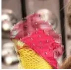
It is a method for displaying a video which only shows a part of an image on every frame of it. This method is the most commonly used in television[1]-[2]. Interlacing is done by only displaying either even or odd rows, or diagonally. Interlace scan often shows the effect of horizontal lines, especially on the moving object. The effect is called mice teeth combing effect, see Fig 1. This effect is sometimes seen clearly, but sometimes it is almost invisible.
Figure 1. Mice Teeth effect from Interlaced Video
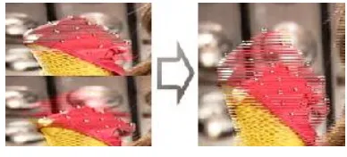
In the interlaced video, combing effect caused by the woven of the two fields becomes one whole frame, see Fig 2. A field has half the vertical resolution (spatial) of a frame. An interlaced video with a resolution of 640 × 480 pixels at 30 frames per second (fps) has sixty 640 × 240 fields per second. To render the fields had become one whole frame, each of the two fields are woven by put the pixel rows are alternately into one frame. Weaving process is the cause the effect of combing[5].
Figure 2. Combining 2 Field become 1 Frame
source: http://casualmuxer.wordpress.com/2008/07/22/sekilas-tentang-interlaced-video/
3.
DE-INTERLACE
De-interlace is a converting process of interlaced video which composed of a set of half part images to be whole image (non-interlaced). Several types of methods are commonly used are blend, bob, discard, linear, doubler, mean, motion blur, and motion compensation.
Blend method is often used on the TV screen. De-interlacing blending produces a little bit blur effect. Blending method performs mixing between the simulated and motion blur as well as combining two consecutive images together sequently. This method reduce the quality a quarter of the original quality [1]-[4].
Area-based methods do not blend in all the parts, but only in the mice teeth area. This can be done by comparing the frame by time or position. This way will give good results in scenes that do not involve a lot of movement, so, no blur is produced.
Another frequently used method is the method doubler. After the disposal of one field, e.g. the even lines, then on even-numbered rows are filled with previous odd lines copy value. This method is often used because it does not require a long processing time. Interpolation method calculates the mean or average of the remaining neighbor fields[5]. For example, there is an image resolution of 5 x 5 as in Fig 3 (left). From the top to bottom are line [0..4] and from left to right are columns [0..4]. If interlace even fields only is applied, then the even lines will be eliminated, and the rest is just odd lines will produce an image as shown in Fig 3 (middle). If diagonal interlace is applied, then it will produce Fig 3 (right), where ‘X’ states the removing data, and O states remaining data.
Figure 3. Original image (left), even field only (centre), diagonal interlace (right)
4.
GENERAL SOFTWARE SYSTEM
This application is divided into two sections, client interface as a medium for displaying results of interlaced video, and server as data processing before data is sent. The outline of the system software can be seen in Fig 4.
Video AVI Format Convert Into Frame Interlace the Frame
Server Side
Server Side
Client side
Client side Send Data through Network
Deinterlace the Frame display
Figure 4. General Software System
4.1
Server System
In the server side, there are several important steps that must be done. There are three main processes on the server, the Open Video Publication, Video Registration, Publication and Video.
Open Video Publication
The first time the server runs, the Open Publication Video will be done. The server chooses a video file which will be published. Then the server initiates the publication of the desired video. The server will send information about the video which will be published as well as the server IP multicastly to all active clients. Data contain author, title of video, ports, and video address.
Registration Video
In the video the registration process, the server receives the IP of the client listed in the published video group. Video’s information will be displayed on the user screen. Beside that, the server can perform other activities, multicast features. Through these features the server sends the output of send-image to the client that has been registered earlier. When the client receives the IP of the user who access the video, the server will perform its data storage. After storing the data, the server can perform multicast to do at any time, not only occur during multicast.
Video Publication
In the process of publication of this video, the server sends the result of the converted video image. Before the image is sent to the client, the image will be processed first, using the interlace method. Then server multicast to all clients connect to the server.
Interlace Scanning Frame
Mulai
Figure 5. Interlace Scanning Frame Flowchart
4.2
Client System
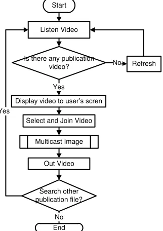
Client side has many features, Refresh, Join Video, Pause, Download Video. General flowchart of the server side is showed in Fig 6.
Start
Listen Video
Is there any publication video?
Display video to user’s scren Yes
Figure 6. Interlace Scanning Frame Flowchart
Multicast Image
The multicast process starts by setting up image image stream through a socket for receiving the transmitted image server. Once the image is received, the image data stream is not directly displayed on the screen. It would be processed first, which performed in order to regenerate normal size image and the fulfil particular pixel on the image which is remain, processed by interpolation de-interlace or mean. Flowchart multicast image can be seen in Fig 7.
Figure 7. Multicast Image Generate Image
Insert bitRusak value into bitmapByte (i,j*2+1) New bitmapByte as bitmapbytes (image) and Set Size bitmapByte New bitRusak as
Figure 8. Generate Image Process De-interlacing
image
i=0
If (i<Height) Yes j=0
If(j<Width)
if ((i % 2 == 0 && j % 2 == 0) || (i % 2 == 1 && j % 2 == 1))
Yes
J++ i++
No
Return image New bitmapByte as bitmapbytes
(image) and Set Size bitmapByte
bitmapByte.unlockBitmap() bitmapByte.lockBitmap()
No Height = image.height
Width = image.width
No
dataR = 0, dataG = 0 dataB = 0, Counter = 0
K = i-1 Yes
If (k<=i+1)
L=j-1 Yes
If (l<=j+1) K++ No
Insert dataR / counter, dataG / counter,
dataB / counter into bitmapByte
L++ No
if ((k >= 0 && k < height) && (l >= 0 && l < width))
Yes
No
if ((k == i - 1 && l == j) || (k == i + 1 && l == j) || (k == i && l == j - 1) ||
(k == i && l == j + 1)) yes
No
dataR = bitmapByte dataR = bitmapByte dataR = bitmapByte
Yes
Counter++
Figure 9. Deinterlacing Proses
5.
EXPERIMENTS
Experiments are conducted to determine the delay generated by each image format. We use four kinds of image format, JPEG, BMP, GIF, and PNG. Testing is performed by comparing the application using the interlace method and without interlacing. Testing is done by taking the initial 10 frames are displayed, the calculation is based on the difference in time required to display each frame received. Testing will calculate the time difference between the current frame and the next appearance on a client. The experimental results using the interlacing and the delay that occurred is displayed in Table 1 and Table 2, while those without interlace shown in Table 3 and Table 4.
Table 1. Time at taking frame using interlace
Frame JPEG BMP GIF PNG
1 7949030 8301421 8891432 8798425
2 7949514 8305212 8892275 8799766
3 7949982 8309050 8893164 8800578
4 7950372 8326319 8894007 8801748
5 7950793 8333994 8894880 8802902
6 7951183 8455924 8895723 8803791
7 7951636 8482070 8896596 8804587
8 7952041 8549369 8897485 8805570
9 7952447 8562458 8898000 8806490
10 7952884 8588650 8898375 8807410
Table 2. Delay frame produced from tabel 1
Frame JPEG BMP GIF PNG
1-2 0.484 3.791 0.843 1.341
2-3 0.468 3.838 0.889 0.812
3-4 0.390 17.269 0.843 1.170
4-5 0.421 7.675 0.873 1.154
5-6 0.390 121.930 0.843 0.889
6-7 0.453 26.146 0.873 0.796
7-8 0.405 67.299 0.889 0.983
8-9 0.406 13.089 0.515 0.920
9-10 0.437 26.192 0.375 0.920
Tabel 3. Time at taking frame without interlace
Frame JPEG BMP GIF PNG
1 9305662 9916094 9854083 9602984
2 9305724 9921211 9854520 9604310
3 9305834 9923769 9854988 9605699
4 9305943 9949431 9855441 9607103
5 9306052 10159923 9855877 9608460
6 9306130 10252510 9856299 9609380
7 9306208 10270544 9856704 9610332
8 9306286 10278250 9857110 9611330
9 9306380 10373224 9857531 9612329
10 9306442 10378372 9857952 9613202
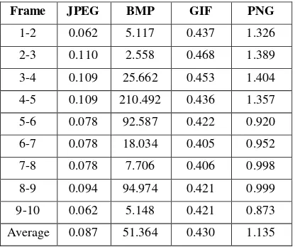
Tabel 4. Delay frame produced from Tabel 3
Frame JPEG BMP GIF PNG
1-2 0.062 5.117 0.437 1.326
2-3 0.110 2.558 0.468 1.389
3-4 0.109 25.662 0.453 1.404
4-5 0.109 210.492 0.436 1.357
5-6 0.078 92.587 0.422 0.920
6-7 0.078 18.034 0.405 0.952
7-8 0.078 7.706 0.406 0.998
8-9 0.094 94.974 0.421 0.999
9-10 0.062 5.148 0.421 0.873
Average 0.087 51.364 0.430 1.135
From table 2 and table 4, the result of compressed videos such as JPEG and GIF are not suitable with this method. It is because of the compact information from the compressed file. It will take no time delay in delivering the file. While the uncompressed video, such as BMP and PNG, this method is well done. This method will make a significant result as expected.
6.
CONCLUSION
Based on the test results can be summed up some of these following:
• Image format types affect the amount of data loss in the event of multicast. Type JPEG format has a lower data rate than the three types, e.g BMP, GIF, and PNG. Raw format file consumes a large time in delivery. It makes our system reconstruct the full image with only a part of the image.
• The type of image format type affects delay in the event of multicast. BMP format type provides the greatest delay compared to other types, JPEG, PNG and GIF. Selection of the proper type of format is recommended to reduce the delay in the event of multicast.
• Diagonal interlace method has less degradation than the odd events interlace method.
• The decline is caused by interlace method is not very significant,
considering the parts are sent only half of the original image.
7.
REFERENCES
[1] G. de Haan, E. Bellers. 1998. De-interlacing: An overview. Proceedings of the IEEE, 86, (9), 1839–1857.
[2] G. de Haan, R. Lodder. 2002. De-interlacing of video data using motion vectors and edge information. Digest of the
ICCE’02, 70–71.
[3] H.S. Oh, Y. Kim, Y. Jung, A. W. Morales, and S.J. Ko. 2000. Spatio-temporal edge-based median filtering for deinterlacing. In ICCE. 2000 Digest of technical papers. International Conference on Consumer Electronics, pages 52 – 53. [4] M. Zhao, G. de Haan. 2004. Intra-field deinterlacing with
advanced up-scaling methods. Proc. of the ISCE, Reading, UK, 315–319.
[5] Interlaced Video. 2011. Sekilas tentang interlaced video. Retrieved Oct. 8, 2011, from