Modelling and Analysis of the Dynamic
Behavior of a Double Cylinder Inline 650cc
Gasoline Engine with Crank Angle 0o for
Rubber Mount
Harus Laksana Guntur1 and Karina Yulia1
AbstractThis paper presents a numerical study and analysis of the dynamic behavior of a double cylinder inline 650cc gasoline engine with crank angle 0o for rubber mount. Numerical study was done by mathematically modeling a double cylinder inline 650cc gasoline engine with crank angle 0o for rubber mount and simulating its dynamic behavior for 3 different connecting rod lengths:115.6mm, 125.6mm, and 135,6mm. Its mathematical model was developed from the physical model of engine produced by local manufacturer. All parameters used in the simulation are based on the engine specification provided by the manufacturer. In the mathematical model, connecting rod length was varied to investigate its influence to the engine’s dynamic behavior. Here, the engine system was modeled as a spring-mass-damper system excited by a periodic force produced by the cylinder working pressure with various excitation frequencies from 1000rpm to 5000rpm. The engine’s dynamic behavior was indicated by vertical motion (bouncing) and angular motion (pitching) of the engine mass, which is presented in displacement, velocity and acceleration. The results show that connecting rod length does not influence the engine’s dynamic behavior. Further, the increase in engine’s angular speed/excitation frequency influence significantly the engine’s dynamic behavior. The detail results of this study are reported and discussed in the paper.
KeywordsDouble Cylinder Engine, Crank Angle, Dynamic Behavior, Rubber Mount, Vibration Response of Engine.
I.INTRODUCTION1
n developing engine, the dynamic behavior/vibration of an engine due to its cylinder pressure is very important to analyze. The change in the crank angle and connecting rod length will yield different dynamic characteristics of engine. Two type of engine mounts are widely used in the automotive industry to isolate the vibration, i.e. hydraulic mount and rubber mount. Hydraulic mount has been used in the automotive industry since the mid-1980s to provide an adaptive vibration isolation system for the engine sturcture to meet increasing customer demand for quieter and smoother riding vehicles [1][2]. The hydraulic mount was introduced to provide a dual damping mode passive vibration isolator to control high-amplitude, low-frequency road-induced vibrations and low-amplitude, high-frequency engine-induced vibrations [3][4].
Prior to the development of an engine, numerical study on the dynamic behavior is very important to be done. Colgate et al reported in his paper the result of his work on modeling of a hydraulic engine mount focusing on response to sinusoidal and composition [5]. Adiguna et al carried out a numerical study to investigate the transient response of a hydraulic engine mount [6]. Meanwhile, very few papers report the study on the dynamic behaviour of an engine with ruber mount. When low cost and simplicity are the main purpose in producing the vehicle, ruber mount is the best choise instead of hydraulic mount.
In this research a numerical study and analysis of the dynamic behavior of a double cylinder inline 650cc
1Harus Laksana Guntur and Karina Yulia are with Departement of
Mechanical Engineering, Faculty of Industrial Technology, Institut Teknologi Sepuluh Nopember, Surabaya, 60111, Indonesia. E-mail: [email protected].
gasoline engine with crank angle 0o for rubber mount was done. In the mathematical model, connecting rod length was varied to investigate its influence to the engine’s dynamic behavior. Here, the engine system was modeled as a spring-mass-damper system excited by a periodic force produced by the cylinder working pressure with various excitation frequencies from 1000rpm to 5000rpm. The engine’s dynamic behavior was indicated by vertical motion (bouncing) and angular motion (pitching) of the engine mass, which is presented in displacement, velocity and acceleration. The detail results of this study are reported and discussed in the paper.
II.PROBLEM FORMULATION
A. Physical Model and Properties of the Engine
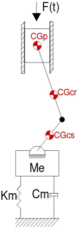
Figure 1 shows the physical model of the double cylinder inline 650cc gasoline engine with crank angle 0o used as the object for the numerical study. The engine properties are shown in Table 1. Several properties, such as: center mass and inertia of all components, are obtained by redrawing the engine parts using drawing software, as shown in figure 2.
B. Excitation Force by the Cylinder Pressure
Figure 3 shows the cycle of cylinder pressure for one cylinder in a double cylinder inline 650cc gasoline engine with crank angle 0o obtained from measurement result. The engine is four strokes engine and has 720o for one full cycle, and the phase lag between cylinder 1 and 2 is 360o. By assuming that all dynamic components of the engine are balance, the cylinder pressure will become the main source of vibration to the engine. Figure 4 shows the cylinder pressure for cyinder 1 and 2 with phase lag of 360o. From the cylinder pressure, the excitation force is obtained by mulitplying the cyinder pressure by the piston frontal area.
The excitation force from the cylinder pressure will be transmitted to the engine through the connecting rod and crank shaft. Figure 5 shows the kinematic diagram of the cylinder, connecting rod and crank shaft. Based on the kinematic diagram, the angular acceleration of the connecting rod is defined by Eq.(1).
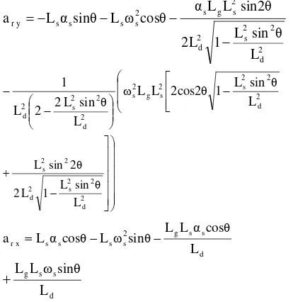
The acceleration of the connecting rod’s center of mass for the y and x direction can be obtained by Eq.(2) and (3), respectively.
2
The force of the crank pin in the y and x direction can be obtained by Eq.(4) and (5), respectively.
F
Therefore, the excitation force applied on engine body
can be determined by Eq.(6).
C. Mathematical Model of the Engine Dynamics
Based on the physical model of the engine, the mathematical model of the engine dynamic, which consist of mass, stiffness and damper can be developed. Figure 6 and 7 show the mathematical model of double cylinder inline 650cc gasoline engine with crank angle 0o for front view and side view, respectively. The excitation force from the cylinder pressure F1(t) and F2(t) transmitted into the engine body are defined by Eq.(6). From the free body force diagram shown in figure 8, the equilibrium of force yields the following equations:
∑ 𝐹= 0 (7)
𝑀𝑒.𝑦̈+𝐾𝑚𝑙.𝑦+𝐶𝑚𝑙.𝑦̇+𝐶𝑚𝑟.𝑦̇+𝐾𝑚𝑟.𝑦=
𝐹𝑦1+𝐹𝑦2 (8)
𝑀𝑒.𝑦̈+𝑦(𝐾𝑚𝑙+𝐾𝑚𝑟) +𝑦̇(𝐶𝑚𝑙+𝐶𝑚𝑟) =
𝐹𝑦1+𝐹𝑦2 (9)
From the free body force diagram shown in figure 9, the equilibrium of moment yields the following equations:
∑ 𝑀= 0 (10)
𝐽𝑜.𝜃̈+𝐾𝑚𝑙(𝜃.𝐿𝑙) +𝐶𝑚𝑙�𝜃̇.𝐿𝑙� − 𝐾𝑚𝑟(𝜃.𝐿𝑟)−
𝐶𝑚𝑟�𝜃̇.𝐿𝑟�=𝐹𝑦1.𝑎 − 𝐹𝑦2.𝑏 (11)
Me:engine mass [kg], Kml: left side-rubber mount
stiffness [N/m], Kmr:right side-rubber mount stiffness
[N/m], Cml:left side-rubber mount damping [N-s/m],
Cmr:right side-rubber mount damping [N-s/m],
Fy1&Fy2:excitation force from the 1st & 2nd piston [N].
D.State Variable Model and Block Diagram
From the equation of force and moment equilibrium, the state variable model of the engine dynamic can be developed. Assuming 𝑦̇=𝑣 and 𝜃̇=𝜔, Eq. (9) and (11)
The state variable equation of the system can be written in a general form as: (16). Based on the state variable equation of the system, the block diagram is developed and shown in figure 10.
III.RESULT AND DISCUSSION
A. Bounching of the Engine due to Impulsice Excitation
is 8 µ m /s, and the peak amplitude of the acceleration is 1.5 mm/s2.
B. Pitching of the Engine due to Impulsive Excitation
The pitching of the engine express the angular motion of the engine body and the center of mass as the center of rotation. Figure 14 to 16 show the pitching displacement, velocity and acceleration of the engine body due to impulsive excitation. It is shown that the peak amplitude of the dispalcement due to impulsive excitation is 5 µ-rad, the peak amplitude of the velocity is 400 µ-rad/s, and the peak amplitude of the acceleration is 0.2 rad/s2.
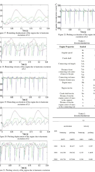
C. Bounching of the Engine due to HarmonicExcitation
Figure 17 to 19 show the bounching displacement, velocity and acceleration of the engine body due to harmonic excitation for the connecting rod length of L1:115.6 mm. In this nurmerical work, the connecting rod length was varied for three different value (L1 = 115.6 mm, L2 = 125.6 mm, L3 = 135.6 mm) as well as the engine speed ( 1000 rpm, 3000 rpm, 5000 rpm). It is shown that the higher the engine speed, the lower the displacement and velocity amplitude. Meanwhile, the acceleration shows the oposite phenomena. This result shows that at high excitation frequency, the amplitude of vibration (displacement and velocity) is lower. However the acceleration is higher. Higher accleration indicates high shaking force applied to the engine mount structure. As the excitation frequency of the engine depends on the engine speed, the design of engine natural frequency should be made outside its operation frequency.
D. Pitching of the Engine due to Harmonic Excitation
Figure 21 to 22 show the pitching displacement, velocity and acceleration of the engine body due to harmonic excitation for the connecting rod length of L1:115.6 mm. In this nurmerical work, the connecting rod length was varied for three different value (L1 = 115.6 mm, L2 = 125.6 mm, L3 = 135.6 mm) as well as the engine speed ( 1000 rpm, 3000 rpm, 5000 rpm). It is shown that the higher the engine speed, the lower the displacement and velocity amplitude. Meanwhile, the acceleration shows the oposite phenomena. This result shows that at high excitation frequency, the amplitude of vibration (displacement and velocity) is lower. However the acceleration is higher. Higher accleration indicates high shaking force applied to the engine mount structure. As the excitation frequency of the engine depends on the engine speed, the design of engine natural frequency should be made outside its operation frequency.
Table 2 to 4 show the root mean square of the bounching and pitching displacement, velocity and acceleration of the engine due to harmonic excitation for various engine speed.
IV.CONCLUSION
A numerical study and analysis of the dynamic behavior of a double cylinder inline 650cc gasoline engine with crank angle 0o for rubber mount is presented in this paper. The numerical study was done by mathematically modeling a double cylinder inline 650cc gasoline engine with crank angle 0o for rubber mount and simulating its dynamic behavior for 3 different connecting rod lengths:115.6mm, 125.6mm, and 135,6mm. Its mathematical model was developed from the physical model of engine produced by local manufacturer. All parameters used in the simulation are based on the engine specification provided by the manufacturer. In the mathematical model, connecting rod length was varied to investigate its influence to the engine’s dynamic behavior. Here, the engine system was modeled as a spring-mass-damper system excited by a periodic force produced by the cylinder working pressure with various excitation frequencies from 1000rpm to 5000rpm. The engine’s dynamic behavior was indicated by vertical motion (bouncing) and angular motion (pitching) of the engine mass, which is presented in displacement, velocity and acceleration. The results show that connecting rod length does not influence the engine’s dynamic behavior. Further, the increase in engine’s angular speed/excitation frequency influence significantly the engine’s dynamic behavior
ACKNOWLEDGEMENT
This research is part of the main research “Development of a Double Cylinder Inline 650cc Gasoline Engine with Crank Angle 0o”, funded by INSINAS program, Minsitry of Research and Technology 2013..
REFERENCES
[1.]W.C.Flower,”Understanding hydraulic mount for improved vehicle noise, vibration and ride qualities”, SAE Technical Paper Series 850975, 1985.
[2.]Benjamin B., Jason T. Dreyer, Rajendra Singh,“Experimental study of the hydraulic engine mounts using multiple inertia tracks and orifices: narrow and broad band tuning concepts”, Journal of Sound and Vibration, vol.331, p.5209-5223, 2012.
[3.]Song He, Rajendra Singh,“Approximate step response of a nonlinear hydraulic mount using a simplified linear model”, Journal of Sound and Vibration, vol.299, p.656-663, 2007. [4.]J.Christopherson, G.Nakhaie Jazar,“Dynamic behavior comparison
of passive hydraulic engine mounts.Part 1:Mathematical analysis”, Journal of Sound and Vibration, vol.290, p.1040-1070, 2006. [5.]J.E.Colgate, C.T.Chang, Y.C.Chiou, W.K.Liu,
L.M.Keer,”Modeling of a hydraulic engine mount focusing on response to sinusoidal and composition excitations”,Journal of Sound and Vibration,vol.184, p.503–528, 1998.
[6.]H. Adiguna, M. Tiwari, R. Singh, “Transient response of a hydraulic engine mount”, Journal of Sound and Vibration, vol.268, p.217–248, 2003.
Figure 1. Physical model of the double cylinder inline 650cc gasoline engine with crank angle 0o
Figure 2. The engine redrawing result
Figure 3. The cycle of cylinder pressure for one cylinder of a double cylinder inline 650cc gasoline engine with crank angle 0o
Figure 4. The cycle of cylinder pressure for two cyinder of a double cylinder inline 650cc gasoline engine with crank angle 0o
Lg Ld
Cgd
Ls
A B
C
y
x
θ β
ω 1
Figure 5. Kinematic diagram of piston, connecting rod and crank shaft
Figure 6. Mathematical model of the engine for front view
Figure 7. Mathematical model of the engine from side view
Me
Kml Cml F1(t)
Y
X
F2(t)
Kmr Cmr CGm
CGcs
CGcr CGcr
CGcs
Lr Ll
a b
CGp CGp
θ
Me
Km
Cm
F(t)
CGp
CGcr
Figure 8. Free body force diagram of the engine Figure 9. Free body force-moment diagram of the engine
Figure 10. Block diagram of the system
Figure 11. Bounching displacement of the engine due to impulsive excitation.
Figure 12. Bounching velocity of the engine due to impulsive excitation.
Figure 13. Bounching acceleration of the engine due to impulsive excitation
Figure 14. Pitching displacement of the engine due to impulsive excitation
Figure 15. Pitching velocity of the engine due to impulsive excitation
Figure 17. Bounching displacement of the engine due to harmonic excitation of L1
Figure 18. Bounching velocity of the engine due to harmonic excitation of L1
Figure 19. Bounching acceleration of the engine due to harmonic excitation of L1
Figure 20. Pitching displacement of the engine due to harmonic excitation of L1
Figure 21. Pitching velocity of the engine due to harmonic excitation of L1
Figure 22. Pitching acceleration of the engine due to harmonic excitation of L1
TABLE 1. ENGINE PROPERTIES
Engine Properties Symbol Value
Angular speed
ω1 104.7 rps
ω2 314 rps
ω3 523.3 rps
Crank shaft Ls 0.04 m
Connecting rod length
Ld1 0.12 m
Ld2 0.13 m
Ld3 0.14 m
Distance from connecting rod center
of mass to the pin
Lg1 0.024 m
Lg2 0.03 m
Lg3 0.03 m
Connecting rod mass Md 0.16 kg
Cylinder frontal area A 4345.3 mm²
Engine mass Me 91 kg
Engine inertia
J1 0.055 kg.m²
J2 0.058 kg.m²
J3 0.06 kg.m²
Crank shaft inertia Ixx 0.008 kg.m² Distance from the
engine center of mass to the support
Ll 0.09 m
Lr 0.087 m
Distance from the engine center of mass
to the connecting rod
a 0.07 m
b 0.067 m
TABLE 2. ENGINE PROPERTIES
L1
rpm
acceleration velocity displacement
bouncing pitching bouncing pitching bouncing pitching
(m/s²) (rad/s²) (m/s) (rad/s) (m) (rad)
1000 56,134 89,637 0,471 0,397 0,011 0,009
3000 164,308 306,562 0,335 0,4695 0,005 0,004
TABLE 3. ENGINE PROPERTIES
L2
rpm
acceleration velocity displacement
bouncing pitching bouncing pitching bouncing pitching
(m/s²) (rad/s²) (m/s) (rad/s) (m) (rad) 1000 64,741 110,836 0,492 0,435 0,011 0,009
3000 175,171 326,331 0,357 0,492 0,005 0,004
5000 419,841 826,201 0,408 0,726 0,002 0,002
TABLE 4. ENGINE PROPERTIES
L3
rpm
acceleration velocity displacement
bouncing pitching bouncing pitching bouncing pitching
(m/s²) (rad/s²) (m/s) (rad/s) (m) (rad)
1000 61,513 101,639 0,481 0,412 0,012 0,009
3000 174,514 322,159 0,351 0,491 0,005 0,004
5000 433,759 847,453 0,419 0,748 0,002 0,002
𝐴=
⎣ ⎢ ⎢ ⎢
⎡ 0 1 0 0
−(𝐾𝑚𝑙+𝐾𝑚𝑟)
𝑀𝑒 −
(𝐶𝑚𝑙+𝐶𝑚𝑟)
𝑀𝑒 0 0
0 0 0 1
0 0 −(𝐾𝑚𝑙.𝐿𝑙−𝐾𝑚𝑟.𝐿𝑟)
𝐽𝑜 −
(𝐶𝑚𝑙.𝐿𝑙−𝐶𝑚𝑟.𝐿𝑟) 𝐽𝑜 ⎦
⎥ ⎥ ⎥ ⎤
(15)
𝐵=
⎣ ⎢ ⎢ ⎢ ⎡01 0
𝑀𝑒 1 𝑀𝑒 0 0
1 𝐽𝑜
1 𝐽𝑜⎦
⎥ ⎥ ⎥ ⎤