Development of a Model of Hydro Electric Power Generation
Suitable for Low Head
Jorfri Boike Sinaga1*, Novri Tanti1, Ahmad Suudi1, M. Dyan Susila1
1Mechanical Engineering Department, Faculty of Engineering, University of Lampung
*E-mail: [email protected]
Abstract. Rural Electrification Program is a policy of Indonesian government on the electricity sector for the expansion of electricity access in rural areas. Least resources is one of the major causes which has left many villages in Indonesia without
electricity. One solution to these problems is renewable energy resources, and use of these energy resources offer tremendous opportunity to electrify rural areas, including hydro-power. This article describes the equipment and operating principle of a model of hydro electric power generation developed in laboratory of fluid mechanics at the Mechanical Engineering Department, University of Lampung, and also presents the testing results obtained in small irrigation canal of Way Tebu in Banjar Agung Udik Village, Pugung District, Tanggamus County, Lampung Province.
1. Introduction
Lampung Province with an area of 3,528,835 ha has considerable renewable energy resources
potential as a substitution for fossil energy. One of the renewable energy is environmentally friendly is hydro power and it is potential in Lampung Province is estimated to reach 2,697.4 MW [1]. Currently, these potentials are mostly used as large scale hydro power plants. Alternative utilization of hydro power that has been popular in Indonesia and has the potential to be developed in this area is a small-scale hydro power plant or better known as Micro hydro Power Plant (MHPP) and Nano hydro Power Plant (NHPP). Utilization of the potential of water energy is deemed very necessary to supply of high demand of electricity, where currently there is a deficit of electrical energy. This deficit has occurred because of a relatively high rate of electricity demand growth in Lampung Province of 15% per year compared to the government's ability to provide electricity supply [2].
Hydraulic turbines commonly used in hydro electric power generation systems utilize energy of hydro power with high flow head. While many the potential of hydro power only have ultra low head or free flow energy (hydrokinetic energy) and not yet use for the hydro electric power generation.
In this paper, design, develop and testing results of ultra low head hydraulic turbine used in model of
generation system model can be developed to be used as a portable hydro electric power generation
system for future work [5].
1.1. Water Turbine for Very Low Flow Head
For decades scientists have tried to use conventional turbines for low flow heads. Highly efficient water turbines for high flow heads are very expensive when applied to hydropower stations with low or very low heads. The main types of water turbines currently used to harness hydropower are: Kaplan, Francis, Pelton, and cross flow turbines. The Kaplan turbine is one of the water turbines which technically can be used for a two meter head height or a lower water head but the turbine operating unit cost increases up to about four times when the water heads fall from 5 to 2 meters. In 1931 Darrieus patented reaction turbine to use low or very low head flow energy (free flow). This turbine has a drum-like shape with a number of straight or curved blades of airfoil and a shaft that is perpendicular to the fluid flow. This turbine allows high torque for slow current flow, and provides a large fluid flow through the turbine without enlarging the diameter. However, the Darrieus turbine has not been acceptable for large applications, mainly due to fluctuations during rotation and relatively low efficiency. Fatigue failure of the blade generally occurs in this turbine due to the nature of the vibration that occurs. This turbine also has an initial operating problem at low rotational speed due to a straight blade that changes the angle of attack.
Gorlov [6] explained the helical turbine has the same advantages as the Darrieus turbine, for example: able to pass a large mass of water for slow flow, kinetic energy capturing, and the low costturbinefor using a very simple rotor blade. The helical arrangement of the rotor blades also makes the
performance of the helical turbine better as compare with the Darrieus turbine. It results the characteristics: uniform turbine rotation at high speed in relatively slow fluid flow, unidirectional rotation in reversible fluid currents, high efficiency, no fluctuating torque, no cavitation in water for high rotating speed, self-starting better in slow flow of waters.
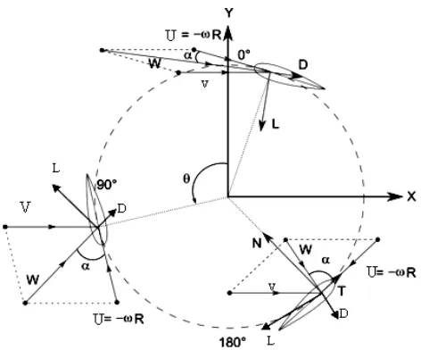
An approximation of the vertical axis turbine is used to calculate the power was generated by this helical turbine blade, as can be seen in Figure 1. The resultant velocity vector (W) is the sum of the velocity vector of fluid (V) and the velocity vector of the advancing blade (U).
⃗
W
=⃗
V
+
(
− ⃗
ω
× ⃗
R
)
(1)where R is the radius of turbine (m), and ω is the angular velocity of turbine (rad/ s).
From the Figure 1, the resulting of fluid velocity varies, the maximum is found for θ = 0O and the
minimum is found for θ = 180O, where θ is the azimuthal or orbital blade position. The angle of
attackα is the angle between the resultant vector velocity (W), and blade's chord. From geometrical considerations, the resultant of flow velocity and the angle of attack are calculated as follows:
W=V
√
1
+
2
λ
cos
θ+
λ
2 (2)α
=
tan
−1(
sin
θ
Figure 1.Forces and velocities acting in a vertical axis wind turbine for various azimuthal positions.
where λ is tip speed ratio, and can be calculated by using the following equation
λ
=
ω R
U
(4)The resultant aerodynamic force is composed in the lift force (FL) and drag force (Fd) which these
forces can be calculated using the following equation:
F
d=
1
2
C
dρ V
2A
(5)
F
l=
1
2
C
lρ V
2A
(6)
where Cd is the coefficient of drag, Cl is the lift coefficient, ρ is fluid density (kg/ m3), V is fluid
velocity (m/s), and A is cross-sectional area of the hydro foil blade (m2).
The force perpendicular to the arm (radius) of turbine, the torque by projecting lift and drag forces can be calculated using the following equation:
T =(Fl.sinα−Fd. cosα)×R (7)
where T is the torque (N.m), F is the force perpendicular to the arm (N), and R is the radius (m). From Equation 7, the shaft power Pb (W) can be calculated using the equation:
P
b=
Tω
(8)1.2. Mathematical Model for Design of Helical Turbine
In Figure 2 [6], It can be seen helical blades formed AME lines on the surface of a cylinder having height L and radius R. The helical blade equation is defined by:
X
=R
cos
ϕ
Y=
R
sin
ϕ
Z
=R ϕ
cos
δ
(9)Figure 2.Projection of the blade line on vertical plane.
As an approximation that the cross section of the blade has the shape of an infinitely thin rectangle with its length equal to the chord c of the blade’s airfoil. This does not change the proportion between lifts and drags after resolution of the reaction force F which can be calculated as:
F = k
oA V
2 (10)where: ko is a constant, ρ is water density, A is projection of the frontal area of the blade on the plane perpendicular to the water flow, and V is velocity of water.
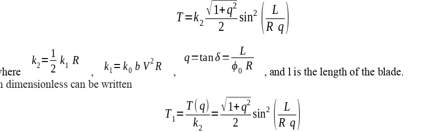
The total starting torque developed by the turbine blades in the water flow can be expressed by the equation
T
=
k
2√
1
+
q
2
2
sin
2
(
R q
L
)
(11)where
k
2=
1
2
k
1R
,
k
1=
k
0b V
2R
,q
=
tan
δ
=
L
ϕ
0R
, and l is the length of the blade. In dimensionless can be writtenT
1=
T
(
q
)
k
2=
√
1
+
q
22
sin
2
(
R q
L
)
(12)Figure 3. The torque relation T1 as a function of angle of blade inclination δ
and the ratio of the turbine height to its radius L/R.
2. Research methods.
2.1 Determining the Potential of Hydro Power
Surveyed must be done to Way Tebu irrigation location in Desa Banjar Agung Udik, to obtain data of flow velocity and cross section area of irrigation canal. These data were used to determine the
potential of hydro power in Way Tebu irrigation canal.
2.2 Determining the Turbine Parameters
The turbine to be designed to use in the model of hydro electric power generation is shown in Figure 5. The parameters of turbine to be determined: height of turbine L, diameter of turbine D, shape of blade, number of blades n, and angle of blade inclination δ.
Figure 5. Model of helical turbine
2.3. Construction of Model of Hydro Electric Power Generation
Scheme of model of hydro electric power generation can be seen in Figure 6. The main components of the model are helical turbine, belt pulleys of power transmission, and generator. This device transforms kinetic energy, derived from river currents or flow of low head, to turn a turbine, which in turn turns a generator that produces electricity.
Figure 6. Schematic of hydro electric power generation model
The efficiency ηsys of model of hydro electric power generation system can be calculated using the
equation:
η
sys=
P
elWhere Pel is electrical power generated (W), ρ is water density (kg/m3), V is velocity of water flow
(m/s), and At is cross sectional area of helical turbine (m2). 3. Results And Discussion
3.1. Potential of Hydro Power of Way Tebu
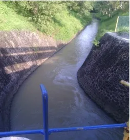
After survey was done to Way Tebu irrigation canal, the data of velocity of flow and cross-sectional
area of the canal was obtained. The velocity of flow in canal was measured by propeller flow meter and obtained velocity of flow of 0.8 m/s. The cross-sectional area of canal is 4.982 m2, as shown in
Figure 7.
Figure 7. Cross sectional area of of irrigation canal of Way Tebu.
Potential of hydraulic energy in the Way Tebu irrigation canal can be calculated by:
P
W=
1
2
ρ A V
3
=
1
,
275
W
Where PW is hydraulic energy of irrigation canal (W), ρ is water density (kg/m3), A is the cross
sectional area of canal (m2), and V is velocity of flow (m/s).
3.2. Turbine Design
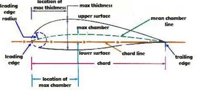
Generally helical turbine uses blade’s airfoil, due to its high efficiency and produces a large pressure difference between two sides of blade to rotate with a considerable force moment in which the force moment is generated by lift and drag force. The lift and drag forces that occur in the airfoil sections are influenced by the shape of blade and the angle of attack. The symmetry airfoils of NACA 0020, NACA 0025 and NACA 0030 airfoils were used for the turbine blade.
According to the conditions of the Way Tebu irrigation canal, as shown in Figure 4, helical turbine to be used has 2 m in diameter and 1m in height. Using equation 12, for the ratio of height to radius of turbine L/R of 2.4, it was obtained the angle of blade inclination δ of 62o as shown in Figure 9
Figure 9.Torque T as a function of angle of blade inclination δ for L/R=2.4
The performance of helical turbine operation is also influenced by relative solidity. It can be calculated using the equation [7]:
σ
=
S
2
L R
(14)where σ is parameter of relative solidity, S is solidity of the helical turbine, L is height of the turbine, and R is radius of the turbine. Solidity of the helical turbine can be calculated using the equation:
S=2n L R
π
(
d+∑
k=1n
sin
(
π kn −d
)
−sin π kn
)
(15)where n is the number of blades, and d is half of the blade’s chord in radians with respect to the axis of rotation.
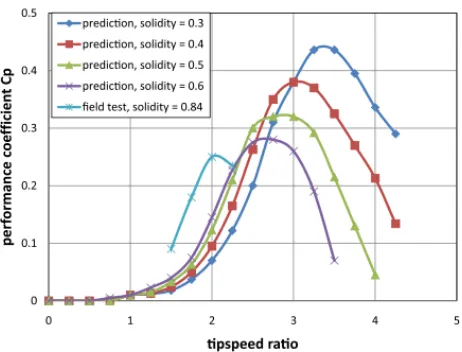
Figure 10.Predicted and measured performance of Darrieus HKTs of varying solidity
The tip speed ratio of turbine operation was determined λ = 3 [7], this is to prevent cavitation during turbine operation. From Figure 10, for tip speed ratio λ = 3, it was obtained the relative solidity σ ≈ 0.4. Based on previous study [9], operating the helical turbine with 3 blades was given the maximum efficiency. Using Equation 14 and 15, it was found the length of chord’s blade of 25 cm.
3. 3. Testing of Model
The helical turbine and the model of hydro electric power generation system tested on the irrigation canal of Way Tebu is shown in Figure 11, and 12. Rotation of the turbine and the generator were measured by tachometer and the electrical power generated by generator was measured by Ammeter and Voltmeter. To increase the performance of helical turbine, the flywheel with various weight was also used in testing of the model of hydro electric power generation system. The flywheel is a rotating mass, and is used as a machine of power store. Energy is stored in the flywheel in form of the kinetic energy
E
=
1
2
Iω
2
(16)
a. Helical turbine used in model.
b. Installation of the hydro electric power generation system
Figure 11.Photograph of the hydro electric power generation system model
3.4. Results and Discussion
Figure 12 are given the testing results of three different blade shape on the performance of model of
hydro electric power generation system. From the testing results in Figure 12a, the model using the blades of NACA 0030 airfoil give the highest efficiency and electrical power, where these values of efficiency and power were found 33.78% and 73.67 W. It was better as compare with the blades of NACA 0025, and NACA 0020 airfoil. This is due to the operation of turbines using the blade of NACA 0030 airfoil produced greater lift forces compared with the blades of NACA 0025 and NACA 0020 airfoil [10]. The best operation of this turbine was at the tip speed ratio of 1.65, where this value is almost near the test result conducted by Gorlov [5].
(a). Influence of the shape of turbine blades on the efficiency
(b). Influence of the shape of turbine blades on the shaft power
0 0.5 1 1.5 2 2.5
Figure 12. The testing results of hydro electric power generation system model with using various
(b). Comparison of the shaft power of hydro electric power generation system model using flywheel
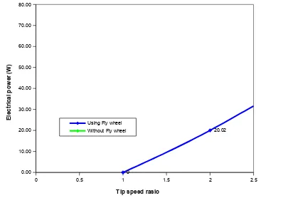
(c). Comparison of the electrical power generatedof hydro electric power generation system model using flywheel with without using flywheel
Figure 13. Comparison of the performance characteristics of hydro electric power generation system model using flywheel with without using flywheel
Testing results of the hydro electric power generation system model using flywheel are shown in Figure 13. It shows an increase in the shaft power and the efficiency of turbine operation. The turbine operation using the flywheel weight of 15 kg generated the highest efficiency and electrical power, where these values were found 36.74% and112.87 W. It show using the flywheel weight of 15 kg gives the amount of energy stored in a flywheel is proportional to release this energy by applying torque to a mechanical load when the turbine receives load from the generator.
Using this turbine in the hydro electric power generation system the potential of low velocity of stream flow energy can be used to generate the electrical energy for the communities living in remote area. To optimize utilizing source of the stream flows energy this hydro electric power generation system can be installed in series or parallel to meet the amount of electricity demand.
4. Conclusions
Based on the results that have been obtained and described above earlier, it can be taken some conclusions:
1. In this research is given helical turbine design method for model of hydro electric power generation
system to use the stream flow energy which has very low head or only kinetic energy such as the stream flow energy in Way Tebu canal irrigation with flow velocity of 0.8 m /s.
3. Improvement of the turbine performance can be conducted by using flywheel, and testing result using weight of flywheel of 15 kg and diameter of 50 cm increase shaft power and efficiency of turbine to 112,87 W and 36,74%respectively.
4. Using this turbine in the hydro electric power generation system the potential of low velocity of stream flow energy can be used to generate the electrical power for the communities living in remote area.
Acknowledgments
This research work was supported by Penelitian Produk Terapan Grant 2017. The authors would like to acknowledge the financial support from Ministry of Research, Technology, and Higher Education of the Republic of Indonesia.
References
[1] Fikri, M. A. 2008 AlternatifEnergiTerbarukandanKonversiEnergi. PLN Lampung Available: www.plnlampung.co.id/warta_PLN.htm. Accesed on March 18, 2010.
[2] Sampurna H 2014 Pertumbuhan Permintaan Listrik di Lampung Cukup Tinggi. Available:
http://www.saibumi.com/artikel-2423-pertumbuhan-permintaan-listrik-di-lampung-ukup-tinggi.html#ixzz4xZCP9k00. Accesed on August 22, 2017.
[3] Jorfri B S, Novri T, and Muhammad B 2012 Rancang Bangun Turbin Air Ultra Low Head untuk Sistem Pembangkit Listrik Tenaga Mikro Hidro (PLTMH) Guna Mendukung Program Desa Mandiri Energi di Provinsi Lampung. Laporan Penelitian Strategis Nasional, Universitas Lampung.
[4] Jorfri B S, Ahmad S, Aang K, Milia R, and Sugiman, 2017 Perancangan Alat Pengujian Model Turbin Air Ultra Low Head untuk Sistem Pembangkit Listrik Tenaga Mikro Hidro (PLTMH), Prosiding Seminar Nasional Energi dan Industri Manufaktur 2017, Universitas Lampung, Bandar Lampung.
[5] Jorfri B S, Ahmad S, Dyan S E, 2018 Optimasi Unjuk Kerja Sistem Pembangkit Listrik Tenaga Mikro Hidro (PLTMH) Menggunakan Turbin Ultra Low Head, Usulan Penelitian Strategis Nasional, Universitas Lampung.
[6] Alexander G 2008 Development of The Helical Reaction Turbine. Final Technical Report (DE-GO1-96EE15669).
[7] Alexander G 2010 Helical Turbine and Fish Safety Available: www.mainetidalpower.com/files/ gorlovrevised.pdf. Accesed on April 22, 2011.
[8] B K Kirke, 2011 Tests on ducted and bare helical and straight blade Darrieus hydrokinetic turbines Renewable Energy. 36: 3013-3022.
[9] Dwi S 2016 Kajian Eksperimental Pengaruh Jumlah Sudu terhadap Unjuk Kerja Turbin Helik untuk Sistem Pembangkit Listrik Tenaga Mikro Hidro (PLTMH). Tugas Akhir Mahasiswa, Jurusan Teknik Mesin, Universitas Lampung.